Creating Kitchen layout, Hatching of Architectural elements and sectional view of an Industrial Building in AutoCad
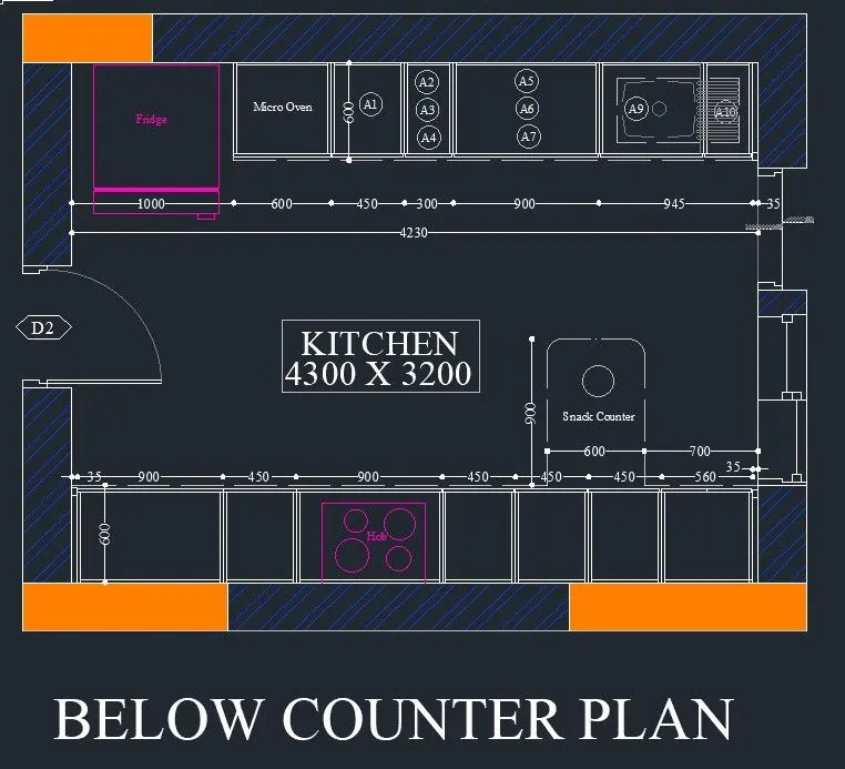
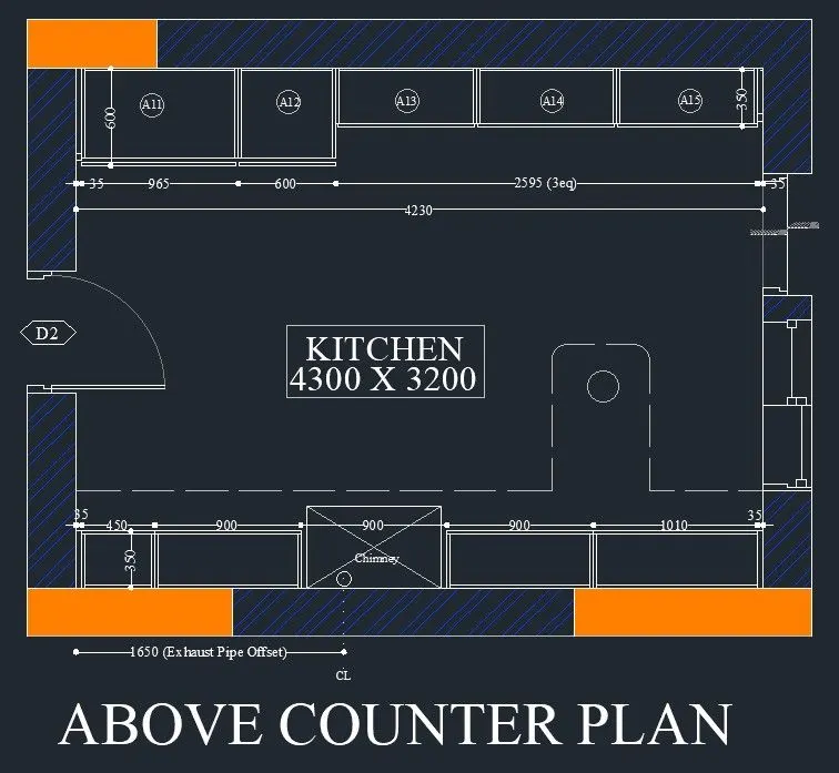
1.Create the layouts of the Kitchen and provide hatches pattern as shown. Also, use blocks wherever required. Provide appropriate dimensions in the plan. Assume the size of doors, appliances and others as per the standards.
Aim: To create the layouts of the kitchen and provide hatches pattern as given figure. To use blocks wherever required and to provide appropriate dimensions in the plan.
Introduction:
XLine: It means construction line. It has infinty edges we used for making wall. By typing "XL" on command line we envoke this tool.
Line: It connects one point to another points. Used to draft various elements.
Trim: This modification tool helps to cut extended edges on the drawing. And to trim inbetween two line or elements. "TR" command to envoke this tool.
Extend: It is also a modification tool, if we have some broken edges or need to extend some portion towards anonther element. "EX" command to envoke the tool.
Offset: Offset the existing element with certain distance. this tool avoid to create new parallel elements.
Layer: Each and every elements has unique property and unique style. This layer tool helps to organize those. Line weight, line style, colour gradient, freeze, lock. it has numerous benefits in Auto CAD drafting.
Hatch: Hatching helps to fill the voids with certain texture on it. If we draft wall means, we mention the brickwork details with the help of hatching.
Circle: Used to make circle elements in the sheet. Type "C" to envoke this tool. Here it is used to draft door.
Procedure:
step-1: Type "UN" to select the units we required "DECIMAL" with precision of 0 and Millimeter.
step-2: Type "LIMITS" to set the limit of the sheet.
step-3: Type "XL" constrcution line to plot and select "H" and "V" angle.
step-4: Type "O" to envoke offset tool to mark wall thickness.
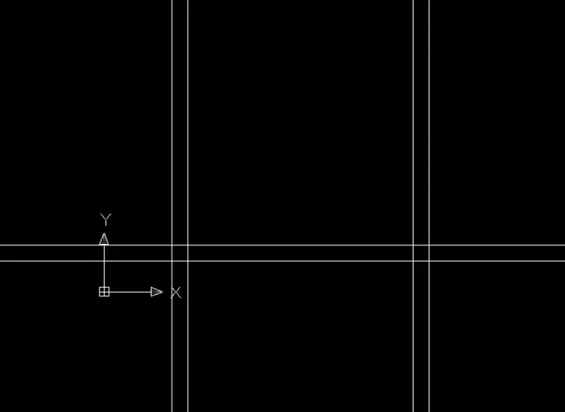
step-5: Type "TR" Trim all extended edges on the drawing sheet.
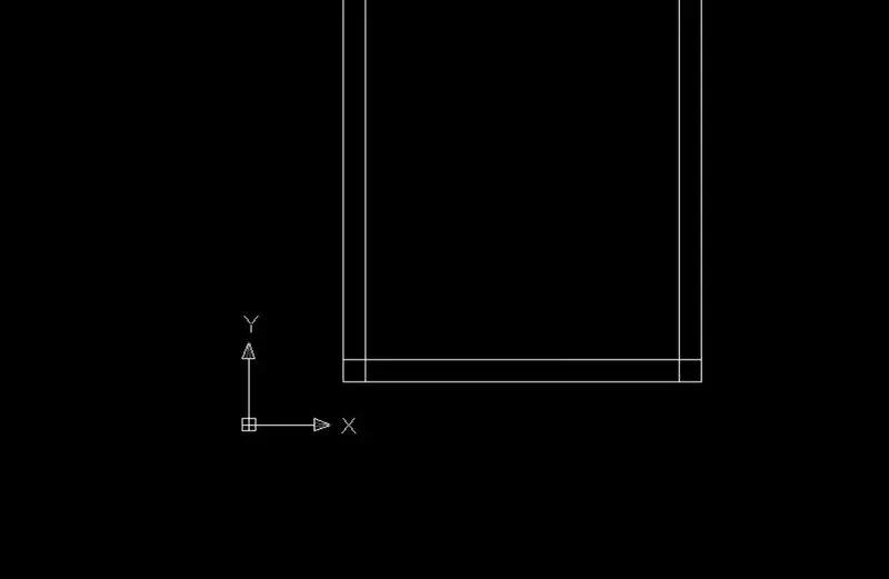
step-6: Type "O" offset to draft remaining elements in the kitchen.
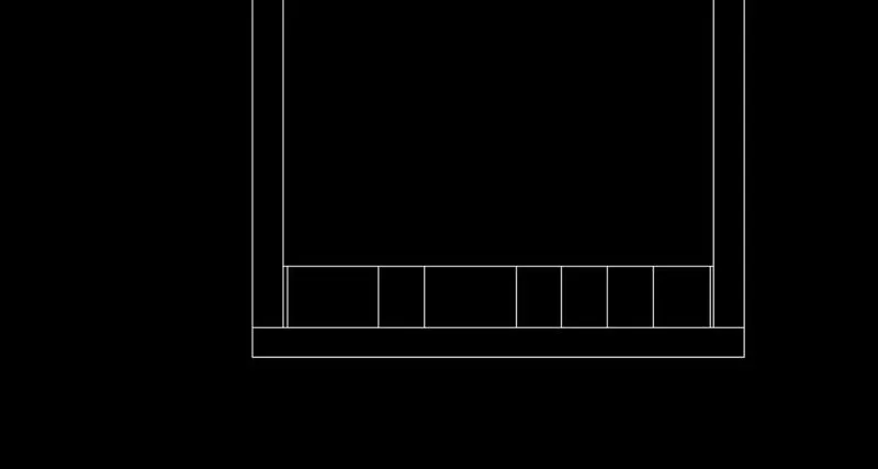
step-7: Load Dashed line in linetype manager and plot in the sheet.
step-8: Type "O" offset to plot all the lines.
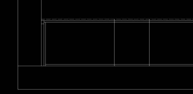
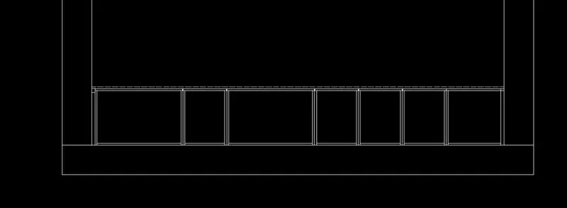
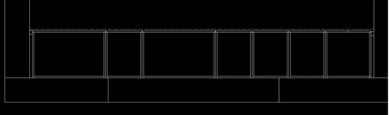
step-9: Type "DIMLIN" to mark all the dimensions on the sheet.
step-10: Type "C" circle to draft hob.
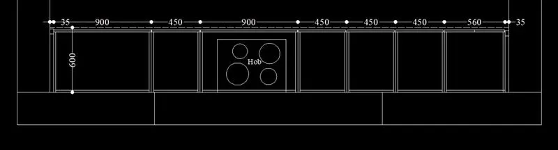
step-11: TYpe "H" hatch to wall thickness.
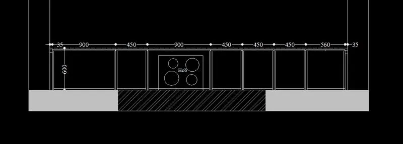
step-12: Type "O" offset to draft another side elements.
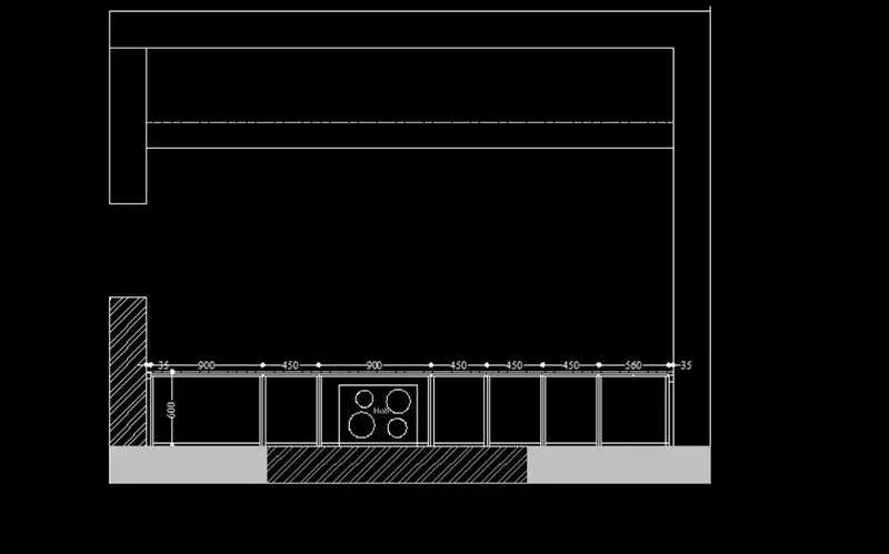
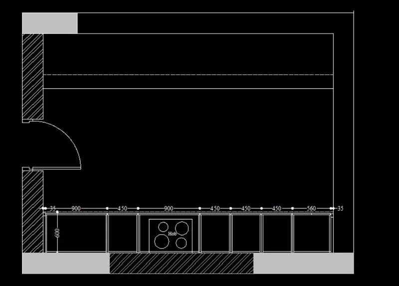
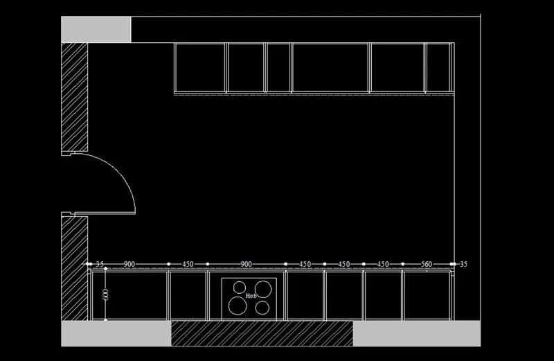
step-13: Type "L" line tool to draft fridge and another elements.
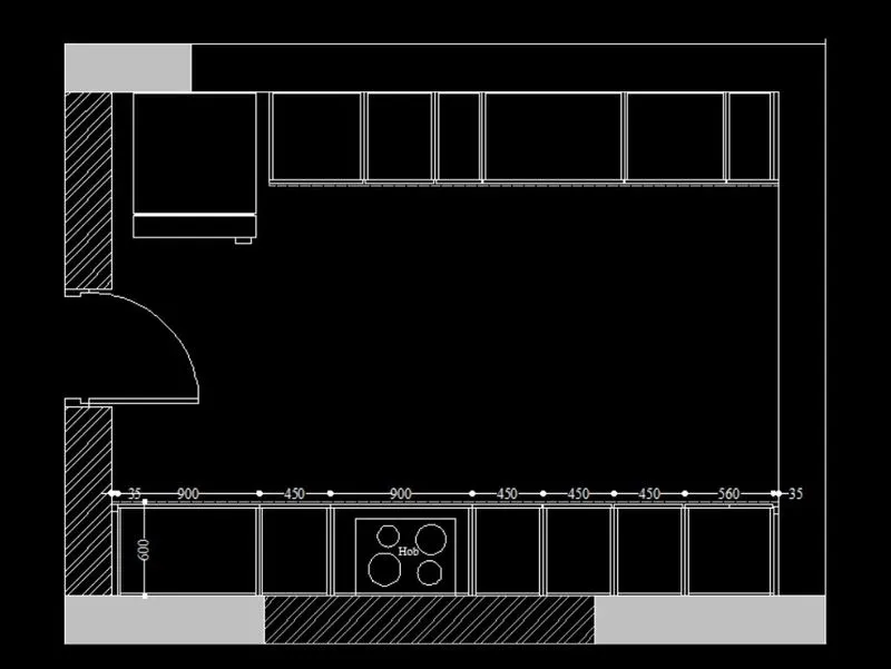
step-14: Type "C" circle to plot notes.
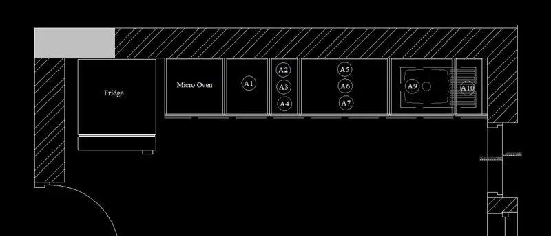
step-15: Type "DT" text to mark all the notes in the sheet.
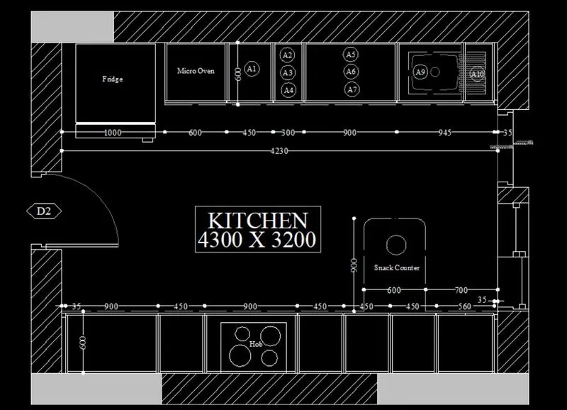
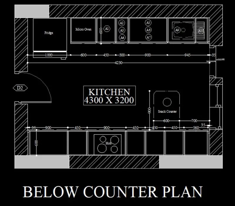
step-16: Type "CO" to copy the previously draft the objects and paste it nearby to draw another object.
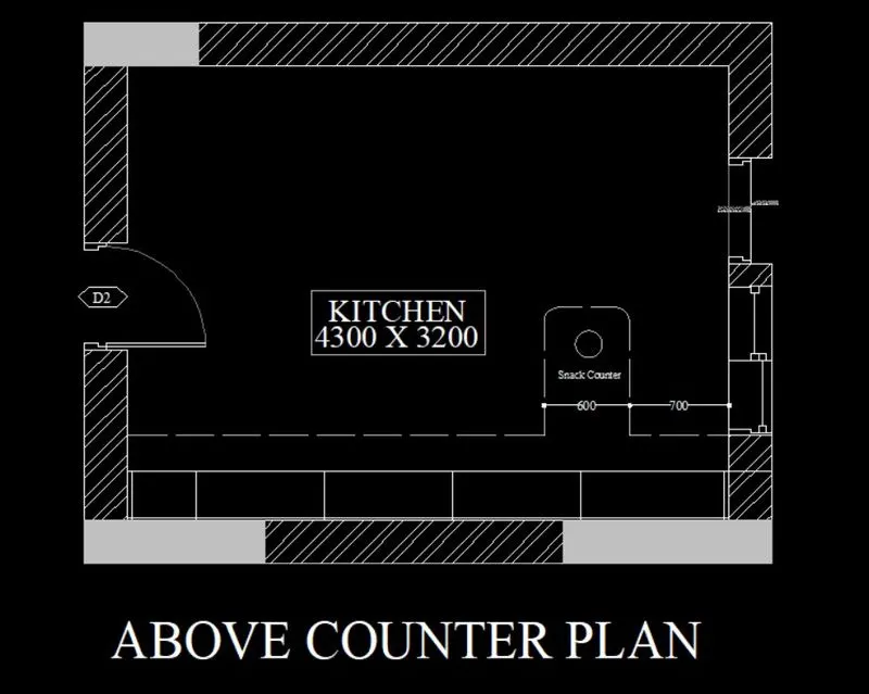
step-17: Type "ERASE" to erase all elements which doesn't required.
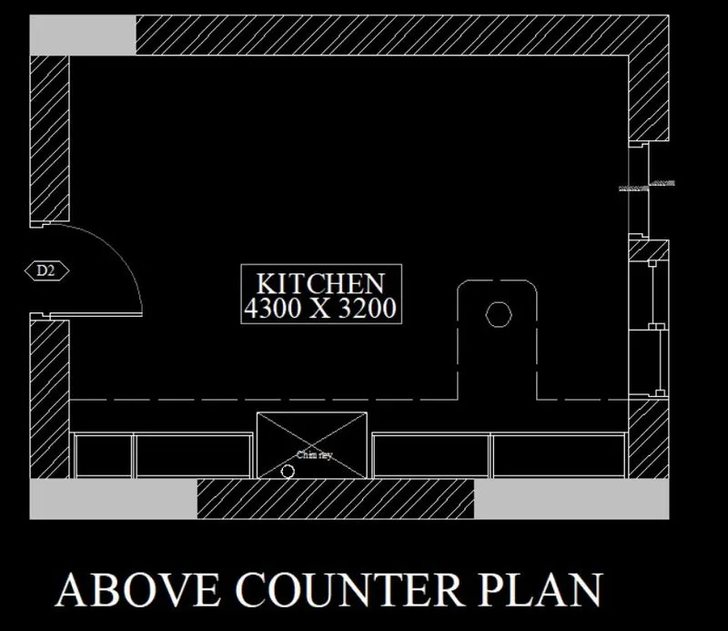
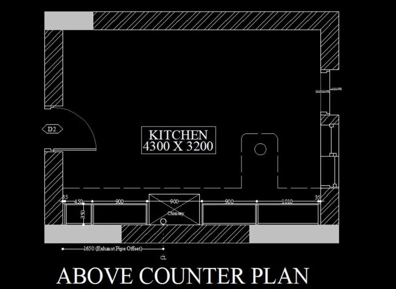
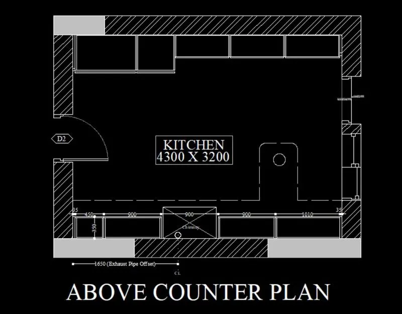
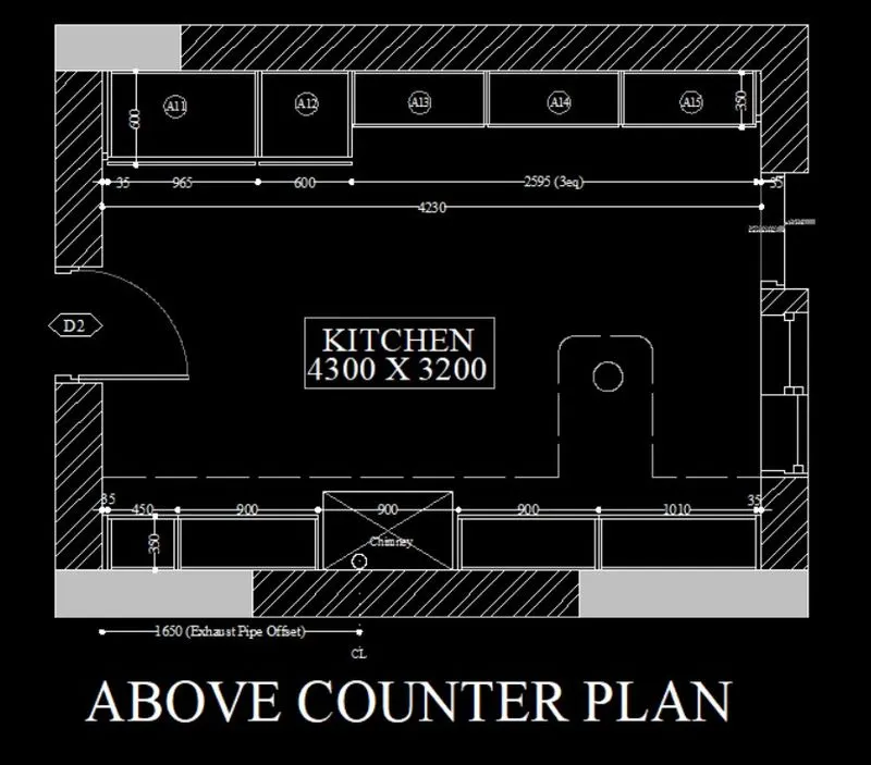
step-18: Create a New Layer to add Hatches and other elements
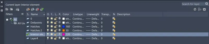
step-19: Select the required element to apply layers
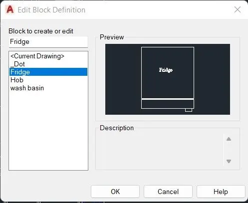
step-20: Type "B" to block components in the drawing
step-21: Select Wash Basin and enter block
step-22: And Select Fridge and enter "B" to block the particular element
RESULT:
Drafting part of kitchen plan of above and below counter area was completed by using AutoCAD.
2. Create the elevation of the plan created in the Challenges 7 and apply proper hatch in the walls, doors, windows, and other architectural elements. Refer to the dimensions in Plans and sections in Challenges 7.
Aim: To create the elevation of the plan created in the challenge 7 and also apply proper hatches in the walls, doors, windows and other architectural elements.
Introduction:
XLine: It means construction line. It has infinty edges we used for making wall. By typing "XL" on command line we envoke this tool.
Line: It connects one point to another points. Used to draft various elements.
Trim: This modification tool helps to cut extended edges on the drawing. And to trim inbetween two line or elements. "TR" command to envoke this tool.
Extend: It is also a modification tool, if we have some broken edges or need to extend some portion towards anonther element. "EX" command to envoke the tool.
Offset: Offset the existing element with certain distance. this tool avoid to create new parallel elements.
Layer: Each and every elements has unique property and unique style. This layer tool helps to organize those. Line weight, line style, colour gradient, freeze, lock. it has numerous benefits in Auto CAD drafting.
Hatch: Hatching helps to fill the voids with certain texture on it. If we draft wall means, we mention the brickwork details with the help of hatching.
Circle: Used to make circle elements in the sheet. Type "C" to envoke this tool. Here it is used to draft door.
Procedure:
step-1: Open Acad
step-2: Open existing plan which we created at challenge 7
step-3: Type "XL" command to draw construction lines for make a reference from plan
step-4: Select "V" vertical lines
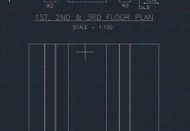
step-5: Type "L" command to draw a horizontal lines with reference to section drawing in that file.
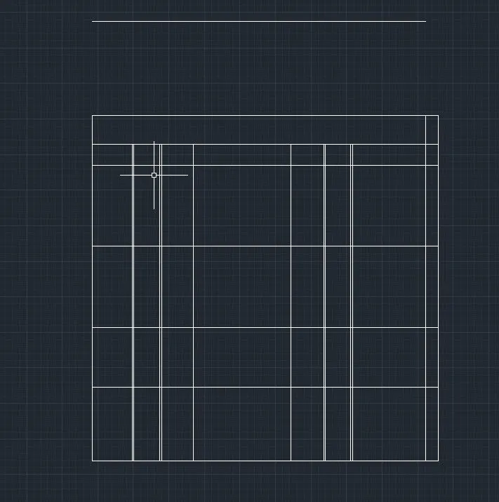
step-6: To draw window element
step-7: Type "L" to draft windows
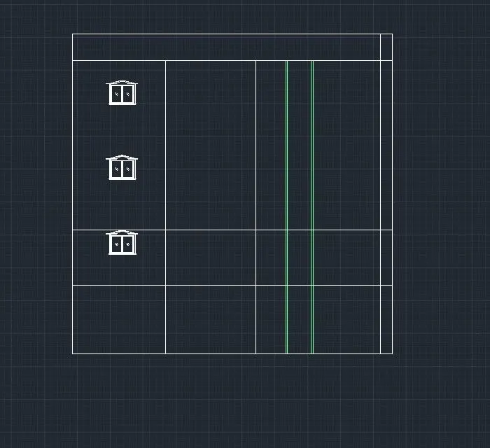
step-8: Type "B" to block the object
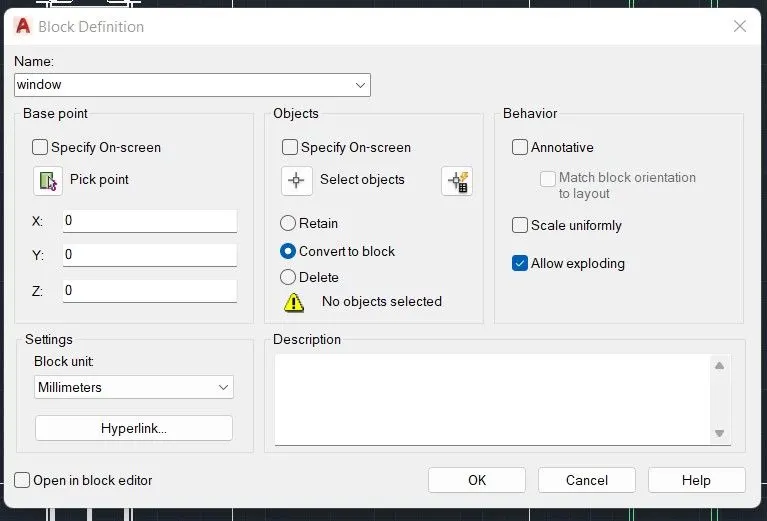
step-9: Type "CO" copy window and paste it into wherever it required
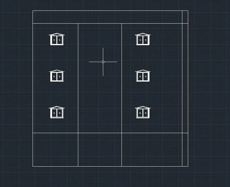
step-10: Type "L" to draw a object
step-11: Type "H" to open a new ribbon tab is called hatch
step-12: Select appropriate hatching tools to make a required object.
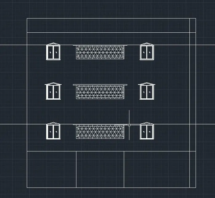
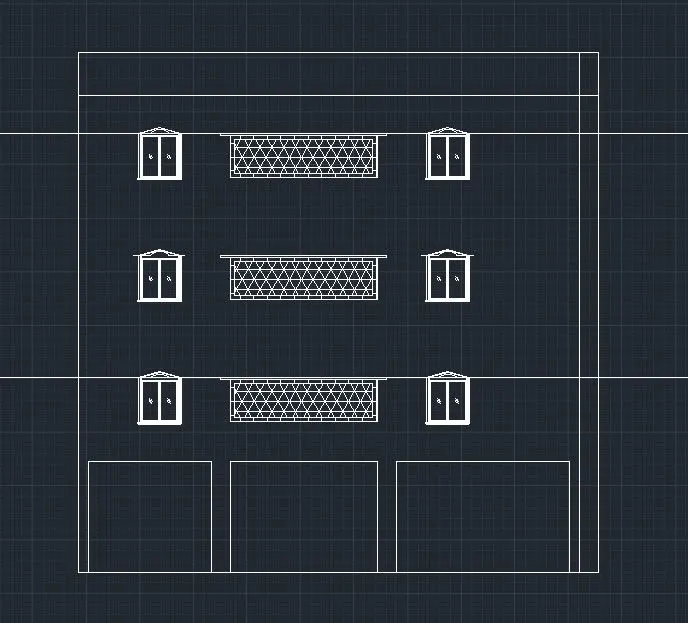
step-13: Type "L" to envoking line tool and draft balcony area
step-14: Type "B" to block specified object that we used to make in balcony element
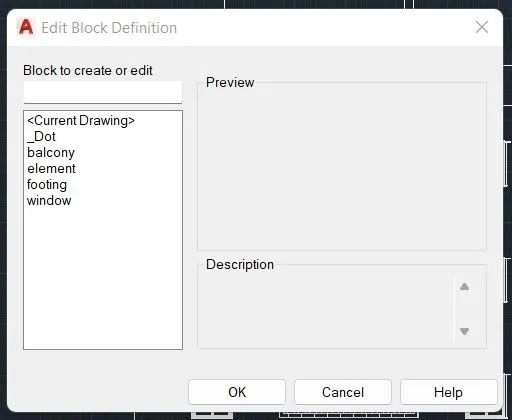
step-15: Type "CO" to copy the balcony and paste into all floors.
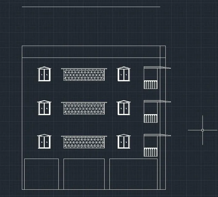
step-16: Type "L" to draw sunshade area
step-17: Type "L" to envoke line tool to draft staircase room in elevation
step-18: Type "REC" to draw rectangle for elevation aesthetics
step-19: Type "DT" to enter title block of the drawing we drew.
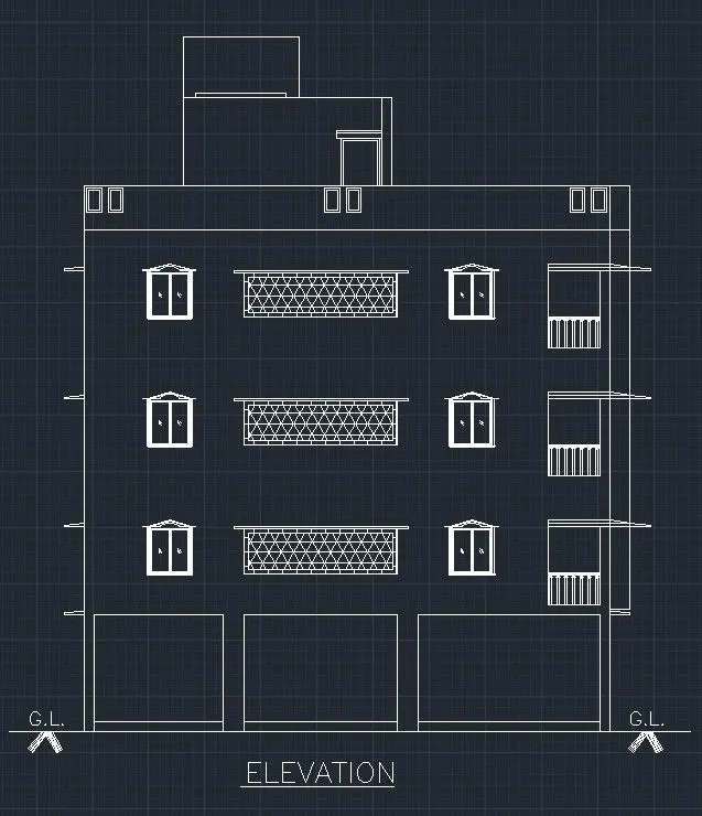
Result:
Created the elevation of the plan created in the challenge 7 and also apply proper hatches in the walls, doors, windows and other architectural elements.
3. Create the section view of an industrial building as shown in Figure. Provide appropriate hatches and dimensions wherever required. Also, provide annotations to the drawing.
Aim: To create the section view of an industrial building as given in figure and to provide appropriate hatches, dimensions and annotations.
Introduction:
Aim: To create the section view of an industrial building as given in figure and to provide appropriate hatches, dimensions and annotations.
XLine: It means construction line. It has infinty edges we used for making wall. By typing "XL" on command line we envoke this tool.
Line: It connects one point to another points. Used to draft various elements.
Trim: This modification tool helps to cut extended edges on the drawing. And to trim inbetween two line or elements. "TR" command to envoke this tool.
Extend: It is also a modification tool, if we have some broken edges or need to extend some portion towards anonther element. "EX" command to envoke the tool.
Offset: Offset the existing element with certain distance. this tool avoid to create new parallel elements.
Layer: Each and every elements has unique property and unique style. This layer tool helps to organize those. Line weight, line style, colour gradient, freeze, lock. it has numerous benefits in Auto CAD drafting.
Hatch: Hatching helps to fill the voids with certain texture on it. If we draft wall means, we mention the brickwork details with the help of hatching.
Circle: Used to make circle elements in the sheet. Type "C" to envoke this tool. Here it is used to draft door.
Procedure:
step-1: Open AutoCAD
step-2: Type "UN" to set the units of the sheet.
step-3: Type "LIMIT" to set the upper and lower corner of the sheet
step-4: TYpe "L" to envoke the line tool to draw section view of the building.
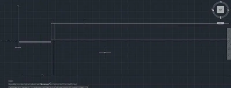
step-5: Type "O" offset the line with specified distance we required.
step-6: TYpe "O" to make RCC wall portion
step-7: Type "CO" to copy the vertical line and paste it into specified distance from figure.
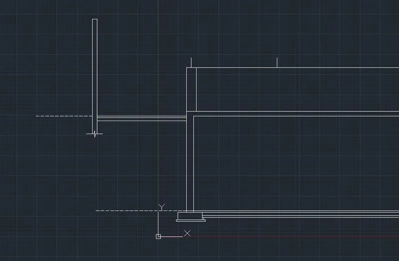
step-8: Type "O" to keep offsetting the line wherever it required with specific distance
step-9: Type "TR" to trim all extended portions of the line
step-10: Type "F" to filler the edges of the foundation
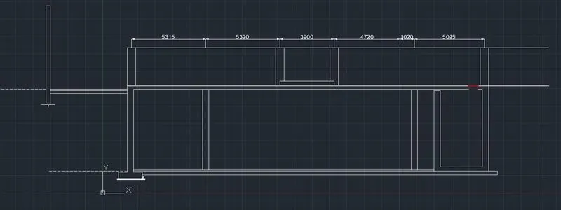
step-11: Type "DIMLIN" to mark the dimensions
step-12: Type "LA" to create a new layer for manhole
step-13: Type "L" to draw manhole cover of the tank
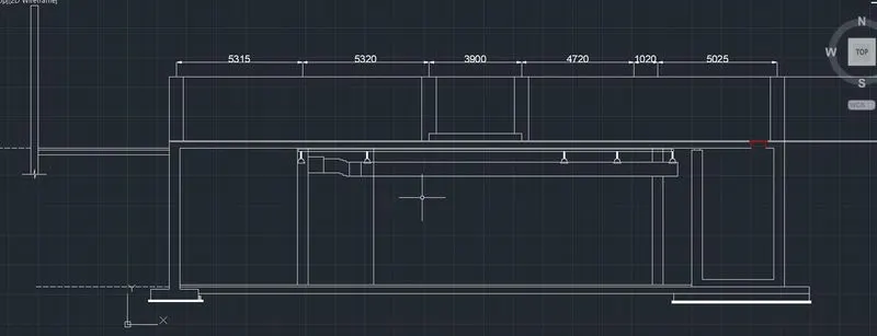
step-14: Type "H" to hatch all concrete portions with proper hatching tool
step-15: Type "H" to hatch P.C.C portion of the fouundation.
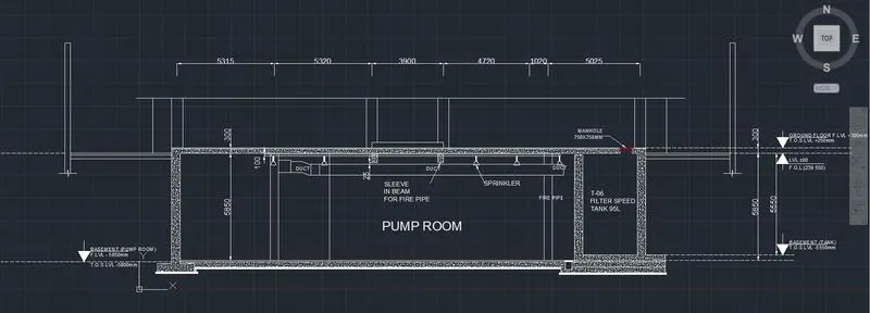
step-16: Type "L" to draw pipeline
step-17: Type "DT" to add text or title in the sheet
step-18: TYpe "QL" to envoke QLEADER tool to mention the object with the leader.
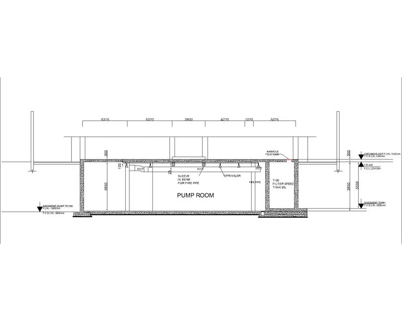
step-19: Type "DT" tp mention the levels of the building.
step-20: Type "DT" to add grids of the building.
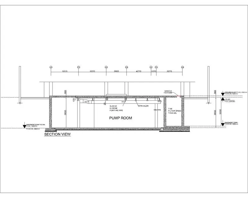
Result:
Created the section view of an industrial building as given in fig. and also provided appropriate hatches, dimensions and annotations by using Auto CAD.