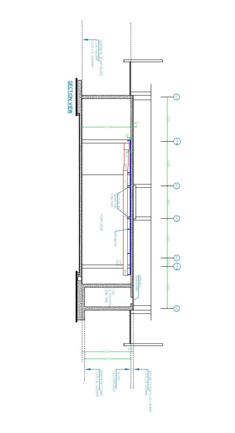
Creating Kitchen layout, Hatching of Architectural elements and sectional view of an Industrial Building in AutoCad
Challenge 9: Creating Kitchen layout, Hatching of Architectural elements and sectional view of an Industrial Building in AutoCad
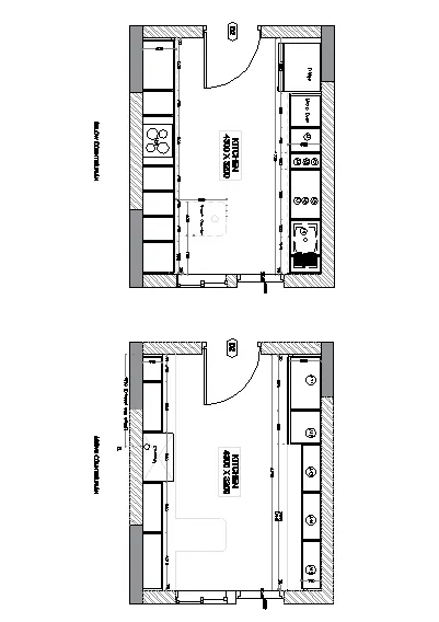
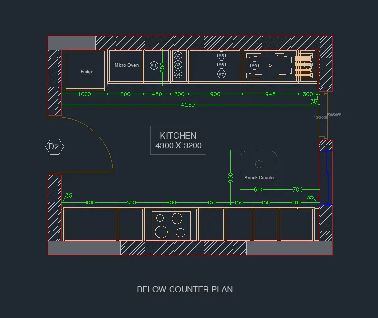
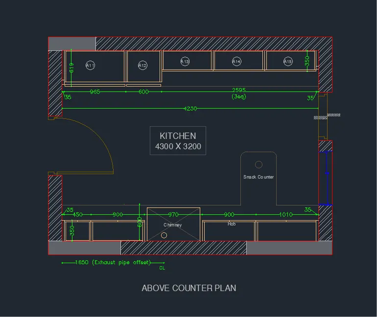
1. Create the layouts of the Kitchen and provide hatches pattern as shown. Also, use blocks wherever required. Provide appropriate dimensions in the plan. Assume the size of doors, appliances and others as per the standards.
AIM
To create the layout of the kitchen and provide hatches pattern as shown in the figure.
INTRODUCTION
The Hatch command in AutoCAD is used to fill patterns inside an enclosed area. The patterns are hatched, gradient, and solid fill. The gradient patterns are defined as a smooth transition between two colors. There are several hatch patterns available in AutoCAD. We can choose the desired pattern from the list of the patterns according to the requirements. The number of hatch lines represented in any pattern can be adjusted with the help of the Hatch Pattern Scale. The Hatch Pattern Scale signifies the spacing between the lines in a particular pattern.
PROCEDURE
Open the AutoCAD Application and create a new AutoCAD file with imperial settings. Set the length type in 'Decimal' and precision (0.00), insertion scale to 'Millimeters' in the Drawing Units and press OK. Set limits and zoom all.
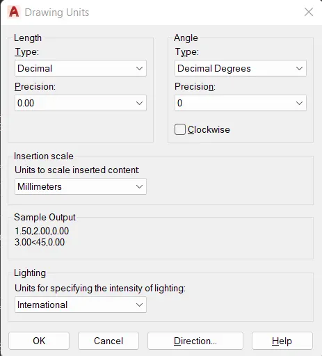
Layers are created, the different layers used in this project is shown below
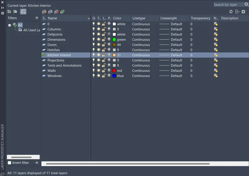
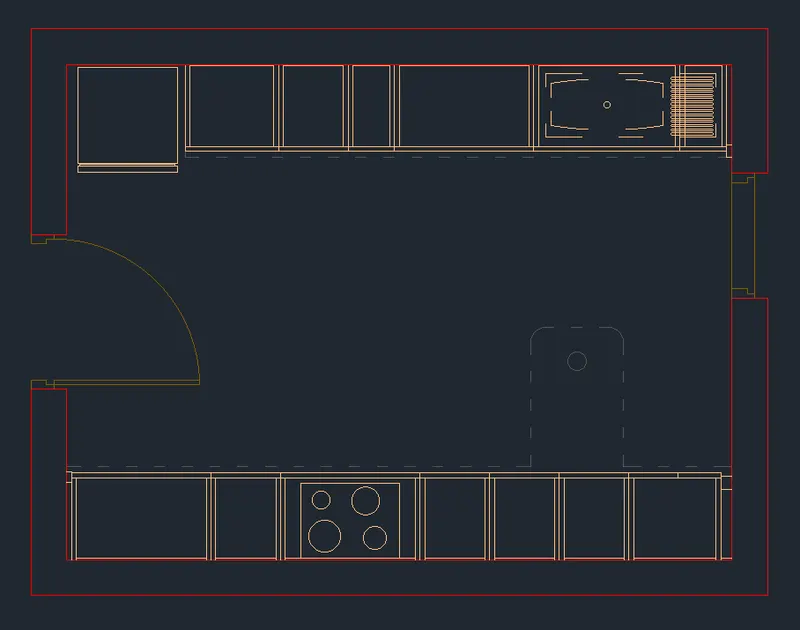
1. Draw the below counter plan
a) Draw the below counter plan outline
- Type 'LA' in the command line and enter to get layers
- Create a new layer 'Walls'
- Type 'REC' in the command line and enter to get rectangle
- Draw a rectangle of size 4300mmx3200mm
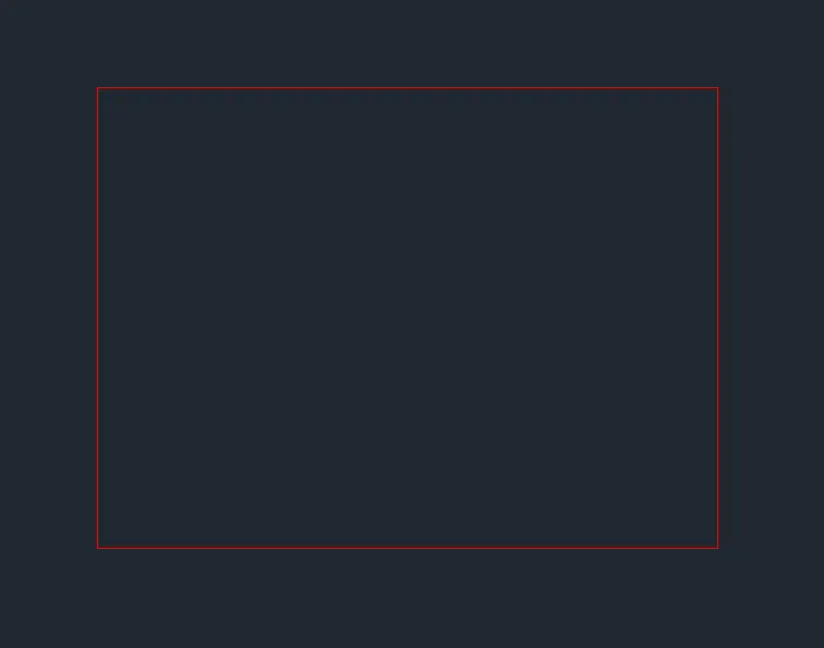
- Type 'OFF' in the command line and enter to get offset tool
- Specify offset distance or [Through/Erase/Layer] : 230
- Select object to offset: Select the rectangle
- Specify point on side to offset or [Exit/Multiple/Undo] : Outside the rectangle
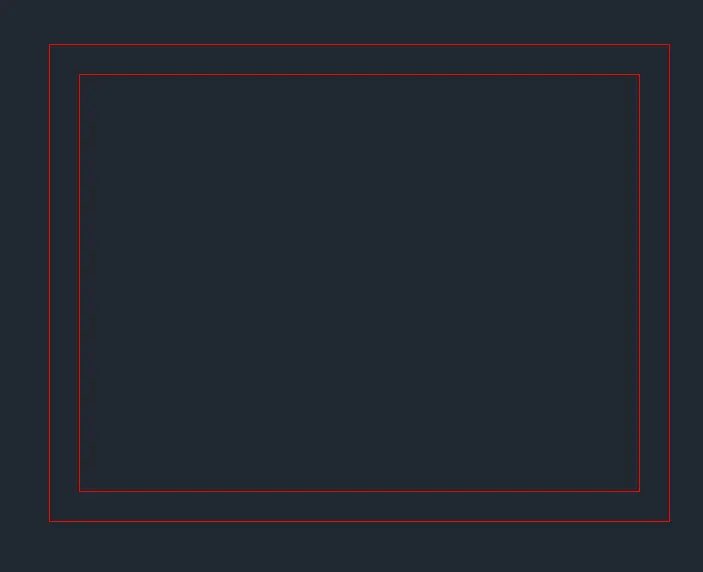
b) Draw the kitchen interiors and projections of the below counter plan and create as blocks
- Type 'LA' in the command line and enter to get layers
- Create a new layer 'Kitchen Interior'
- Type 'REC' in the command line and enter to get rectangle
- Draw rectangles of size shown in the plan
- Type 'OFF' in the command line and enter to get offset tool
- Offset essential lines as shown in the design
- Type 'PL' in the command line and enter to get polyline
- Draw polylines to create kitchen sink
- Type 'C' in the command line and enter to get circle
- Draw a circle in the middel of the sink
- Draw circles to represent the Hob
- Type 'TR' in the command line and enter to get trim tool
- Trim all unnecessary lines
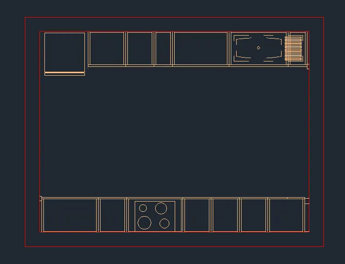
- Type 'LA' in the command line and enter to get layers
- Create a new layer 'Projections' with linetype "ACAD_ISO03W100"
- Type 'PL' in the command line and enter to get polyline
- Draw polylines to create projections of snack counter and all other projections
- Type 'C' in the command line and enter to get circle
- Draw a circle in the snack counter
- Type 'F' in the command line and enter to get fillet tool
- Fillet top two corners of the snack counter with a radius of 100mm
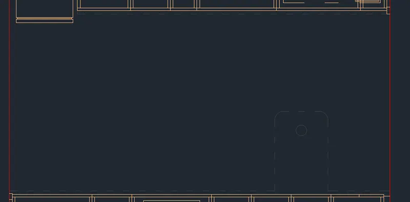
c) Draw doors (1000mmx2100mm, 800mmx2100mm)
- Type 'LA' in the command line and enter to get layers
- Create a new layer 'Doors'
- Type 'OFF' in the command line and enter to get offset tool
- Offset 1330 from outer wall of both sides in the inward direction
- Offset 930mm from the top outer wall in the inward direction
- Offset 1920mm from the bottom outer wall in the inward direction
- Type 'L' in the command line and enter to get line
- Draw line from opening, 60mm in the y direction, then 60mm in the x direction, then 30mm in the -y direction, then 60mm in the x direction and then 30m in the -y direction
- Type 'MI' in the command line and enter to get mirror tool
- Select all the lines drawn and enter, then specify the first (midpoint of the door) and second point of the mirror
- Type 'L' in the command line and enter to get line
- Draw line 940mm in the x direction from the drawn line, then 30mm in the -y direction and then 940mm in the -x direction
- Type 'C' in the command line and enter to get circle
- Draw a circle from one end of the line to the other
- Type 'TR' in the command line and enter to get trim tool
- Trim all unnecessary lines and arcs
- Type 'CO' in the command line and enter to get copy tool
- Select the door frame and paste it in the other side door opening
- Type 'MI' in the command line and enter to get mirror tool
- Select all the door frame and enter, then specify the first (midpoint of the door) and second point of the mirror.
- Type 'L' in the command line and enter to get line
- Draw parallel lines from one end to another
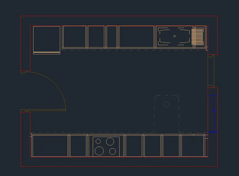
d) Draw the window
- Type 'LA' in the command line and enter to get layers
- Create a new layer 'windows'
- Type 'OFF' in the command line and enter to get offset tool
- Offset 830mm from the bottom outer wall in the inward direction
- Offset 10mm from previous line
- Offset 10mm from previous line
- Offset 880mm from previous line
- Offset 10mm from previous line
- Offset 65mm from left outer wall line in the -x direction
- Offset 95mm from left outer wall line in the -x direction
- Type 'REC' in the command line and enter to get rectangle
- Draw a square of size 25mmx25mm
- Type 'CO' in the command line and enter to get copy tool
- Select the square and place in proper places according to the figure
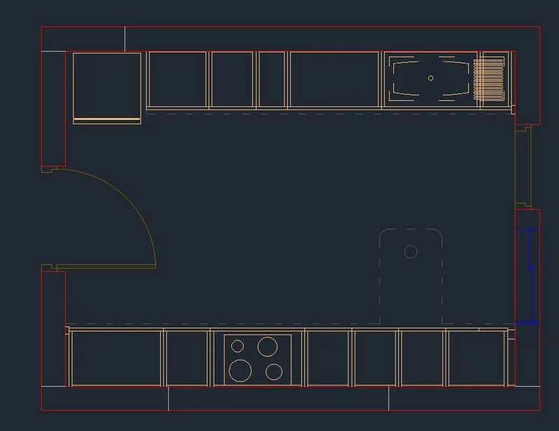
e) Draw the colums shown in the below counter plan
- Type 'LA' in the command line and enter to get layers
- Create a new layer 'Column'
- Type 'REC' in the command line and enter to get rectangle
- Draw a rectangle of size 830mmx230mm
- Draw a rectangle of size 1210mmx230mm
- Draw a rectangle of size 1440mmx230mm
- Type 'MO' in the command line and enter to get move tool
- Select the the rectangles and place them according to the below counter plan
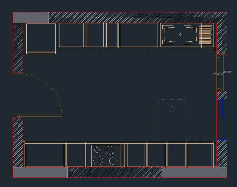
f) Hatching
- Type 'LA' in the command line and enter to get layers
- Create a new layer 'Hatches'
- Type 'H' in the command line and enter to get hatch tool
- Pick internal point: Pick points inside the columns (Pattern: SOLID)
- Pick internal point: Pick points inside the wall (Pattern: ANSI31)
2. Draw the above counter plan
a) Draw the above counter plan outline
- Type 'CO' in the command line and enter to get copy tool
- Select all objects and paste to other side
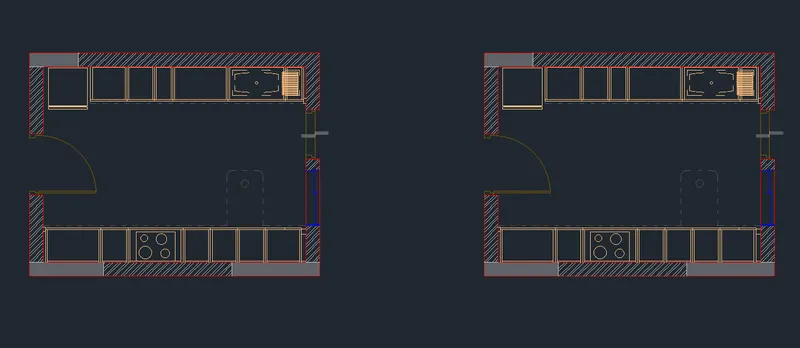
- Type 'E' in the command line and enter to get erase tool
- Select the objects to erase as per the above counter plan
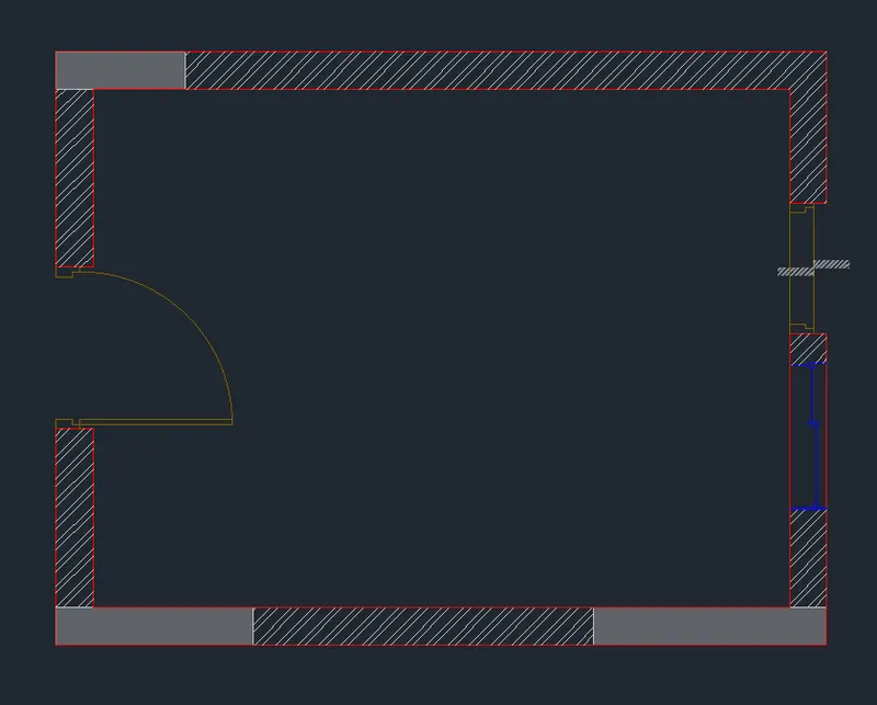
b) Draw the kitchen interiors and projections of the below counter plan and create as blocks
- Select 'Kitchen Interior' layer
- Type 'REC' in the command line and enter to get rectangle
- Draw rectangles of size shown in the plan
- Type 'OFF' in the command line and enter to get offset tool
- Offset essential lines as shown in the design
- Type 'C' in the command line and enter to get circle
- Draw a circle to represent chimney hole
- Type 'TR' in the command line and enter to get trim tool
- Trim all unnecessary lines
- Type 'PL' in the command line and enter to get polyline
- Draw polylines to create projections of snack counter and all other projections from below counter plan
- Type 'C' in the command line and enter to get circle
- Draw a circle in the snack counter
- Type 'F' in the command line and enter to get fillet tool
- Fillet top two corners of the snack counter with a radius of 100mm
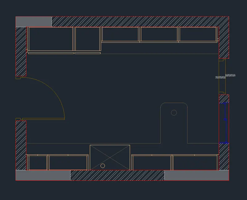
3. Create blocks
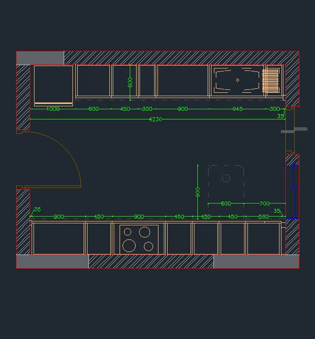
a) Below counter plan 1
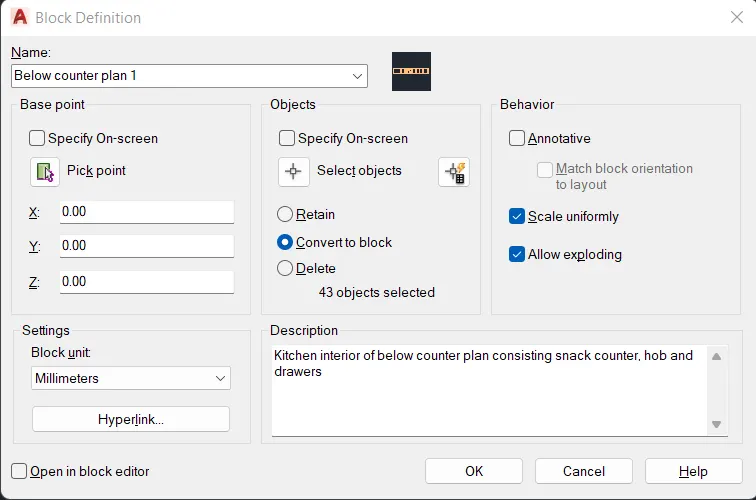
- Type 'B' in the command line and enter to get block definition
- Name: 'Below counter plan 1'
- Base point: Pick point from the screen according to the design
- Objects: Select objects from the bottom part of the plan, click 'Convert to block'
- Behavior: Tick 'Scale uniformly' and 'Allow exploding'
- Settings: Block unit as 'Millimeters'
- Description: 'Kitchen interior of below counter plan consisting Hob and drawers'
- Press OK
b) Below counter plan 2
- Type 'B' in the command line and enter to get block definition
- Name: 'Below counter plan 2'
- Base point: Pick point from the screen according to the design
- Objects: Select objects from the bottom part of the plan, click 'Convert to block'
- Behavior: Tick 'Scale uniformly' and 'Allow exploding'
- Settings: Block unit as 'Millimeters'
- Description: 'Kitchen interior of below counter plan consisting fridge, kitchen sink and drawers'
- Press OK
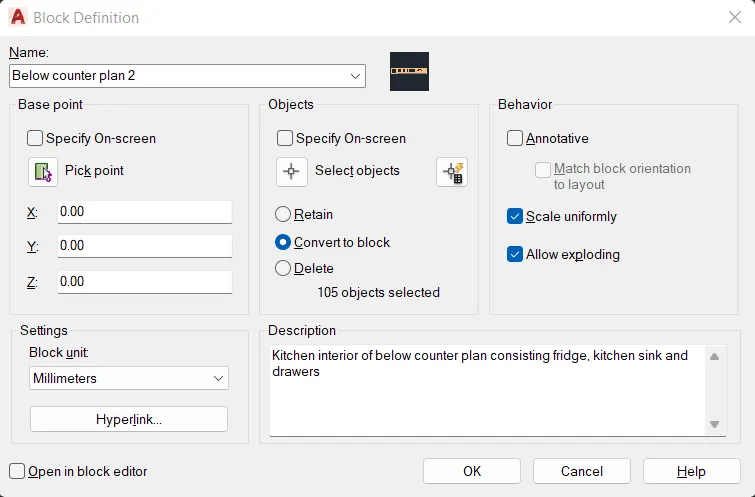
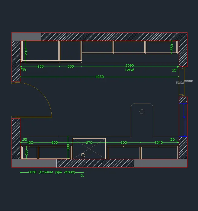
c) Above counter plan 1
- Type 'B' in the command line and enter to get block definition
- Name: 'Above counter plan 1'
- Base point: Pick point from the screen according to the design
- Objects: Select objects from the bottom part of the plan, click 'Convert to block'
- Behavior: Tick 'Scale uniformly' and 'Allow exploding'
- Settings: Block unit as 'Millimeters'
- Description: 'Kitchen interior of above counter plan consisting snack counter, chimney and drawers'
- Press OK
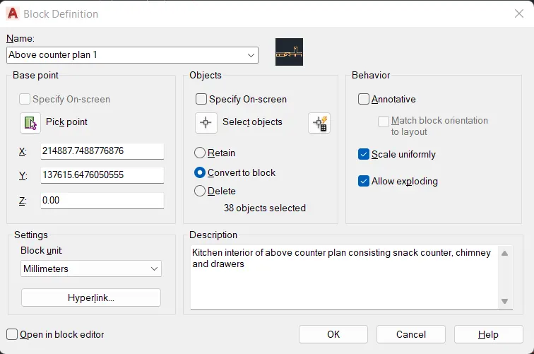
d) Above counter plan 2
- Type 'B' in the command line and enter to get block definition
- Name: 'Above counter plan 2'
- Base point: Pick point from the screen according to the design
- Objects: Select objects from the bottom part of the plan, click 'Convert to block'
- Behavior: Tick 'Scale uniformly' and 'Allow exploding'
- Settings: Block unit as 'Millimeters'
- Description: 'Kitchen interior of above counter plan drawers'
- Press OK
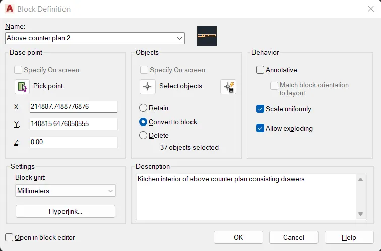
e) Door 1
- Type 'B' in the command line and enter to get block definition
- Name: 'Door 1'
- Base point: Pick point from the screen according to the design
- Objects: Select objects from the bottom part of the plan, click 'Convert to block'
- Behavior: Tick 'Scale uniformly' and 'Allow exploding'
- Settings: Block unit as 'Millimeters'
- Description: 'Door of size 1000mm x 2100mm'
- Press OK
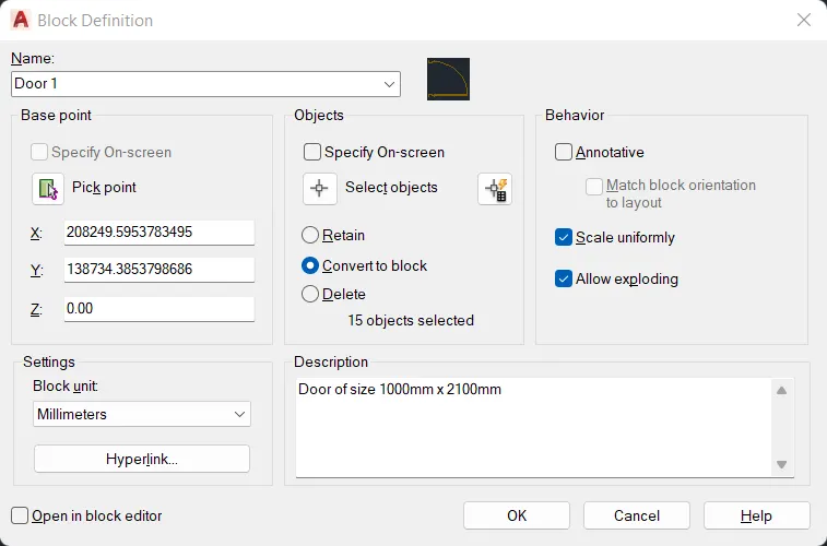
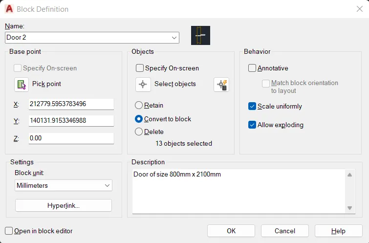
f) Door 2
- Type 'B' in the command line and enter to get block definition
- Name: 'Door 2'
- Base point: Pick point from the screen according to the design
- Objects: Select objects from the bottom part of the plan, click 'Convert to block'
- Behavior: Tick 'Scale uniformly' and 'Allow exploding'
- Settings: Block unit as 'Millimeters'
- Description: 'Door of size 800mm x 2100mm'
- Press OK
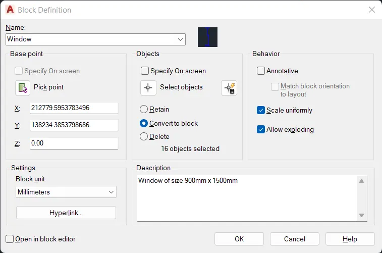
g) Window
- Type 'B' in the command line and enter to get block definition
- Name: 'Window'
- Base point: Pick point from the screen according to the design
- Objects: Select objects from the bottom part of the plan, click 'Convert to block'
- Behavior: Tick 'Scale uniformly' and 'Allow exploding'
- Settings: Block unit as 'Millimeters'
- Description: 'Window of size 900mm x 1500mm'
- Press OK
4. Insert Dimensions
- Type 'LA' in the command line and enter to get layers
- Create a new layer "Dimensions"
- Type 'DIMSTY' in the command line and enter to get dimension style settings
- Dimension Style is created as New
- In Lines, Fixed length extension lines is given as 100mm.
- In Symbols and Arrows, Arrowhead is given as 'Dot small', Arrow size is given as 50mm.
- In Text, Text height is given as 60mm
- In Fit, Overall scale is given as 1
- Type 'DIM' in the command line and enter to get dimension line
- Mark all necessary dimensions
5. Insert texts
- Type 'LA' in the command line and enter to get layers
- Create a new layer "Texts and Annotations"
- Type 'MTEXT' in command line and enter to get text tool
- Type all necessary details as required
- Type 'C' in command line and enter to get circle
- Draw circle around some text as per the plan
- Type 'PLINE' in command line and enter to get polyline tool
- Draw a hexagon around 'D2'
- Type 'REC' in command line and enter to get rectangle
- Draw a rectangle around the main dimension
RESULT
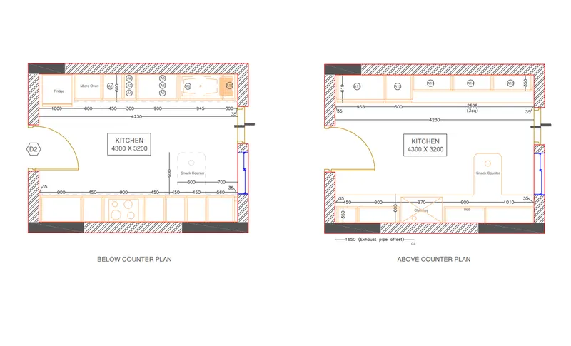
The kitchen layout is drawn as shown in the figure. All dimensions are in 'mm'
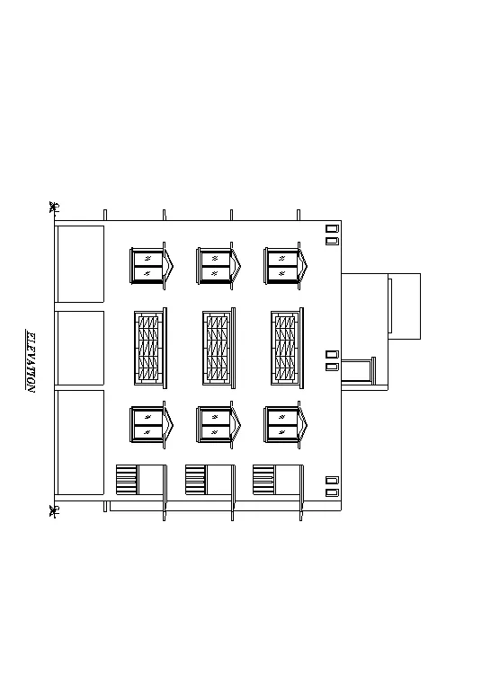
2. Create the elevation of the plan created in the Challenges 7 and apply proper hatch in the walls, doors, windows, and other architectural elements. Refer to the dimensions in Plans and sections in Challenges 7.
AIM
To create the elevation of the plan created in the challenge 7 and apply proper hatch in the walls, doors, windows, and other architectural elements.
INTRODUCTION
The Hatch command in AutoCAD is used to fill patterns inside an enclosed area. The patterns are hatched, gradient, and solid fill. The gradient patterns are defined as a smooth transition between two colors. There are several hatch patterns available in AutoCAD. We can choose the desired pattern from the list of the patterns according to the requirements. The number of hatch lines represented in any pattern can be adjusted with the help of the Hatch Pattern Scale. The Hatch Pattern Scale signifies the spacing between the lines in a particular pattern.
PROCEDURE
Open the AutoCAD Application and click 'Open files' and select 'Week 7' since reference is taken from week 7 challenges.
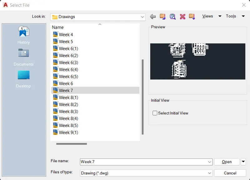
Set the length type in 'Decimal' and precision (0.00), insertion scale to 'Millimeters' in the Drawing Units and press OK. Set limits and zoom all.
Layers are created, the different layers used in this project is shown below
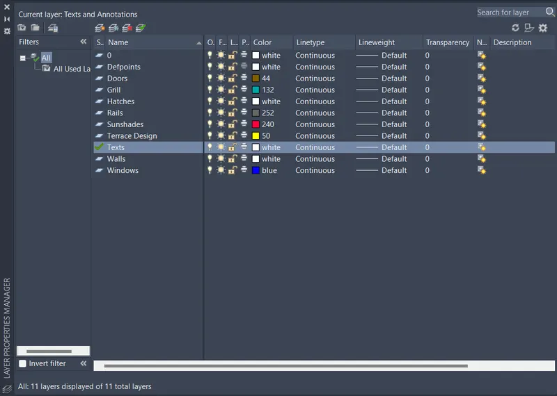
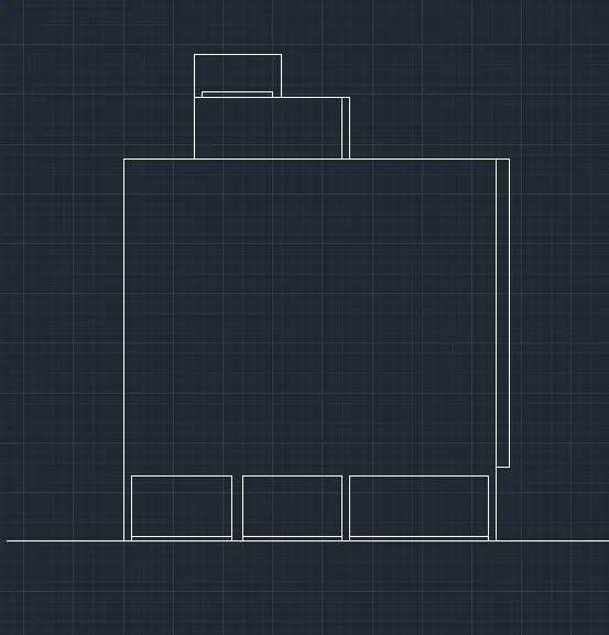
1. Create the elevation outine
- Type 'LA' in the command line and enter to get layers
- Create a new layer "Wall"
- Type 'RAY' in the command line and enter to get ray tool
- Draw rays from the plan and section-AA
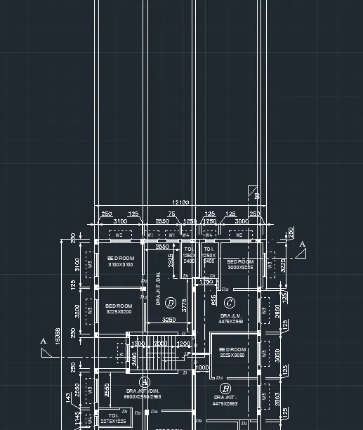
- Type 'CO' in the command line and enter to get copy tool
- Select the 'SECTION-AA' and paste it near the new rays drawn
- Type 'RAY' in the command line and enter to get ray tool
- Draw rays from the section-AA
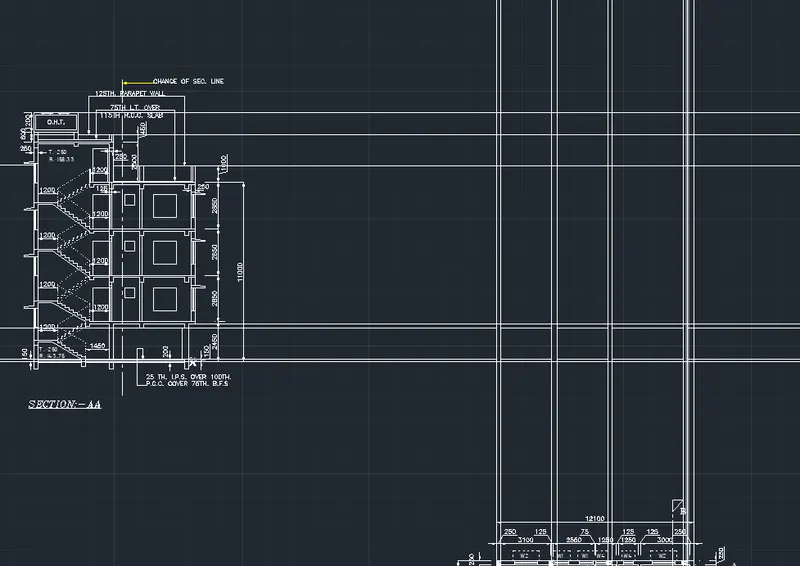
- Type 'TR' in the command line and enter to get trim tool
- Remove all unnecessary lines
2. Draw side sunshade
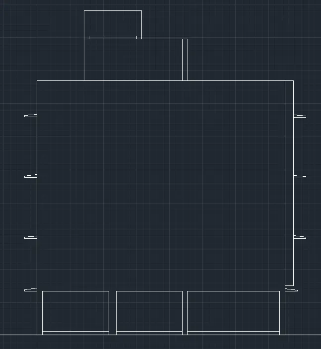
- Type 'LA' in the command line and enter to get layers
- Create a new layer "Sunshades"
- Type 'CO' in the command line and enter to get copy tool
- Select the sunshades in the 'SECTION-AA' and paste it in the elevation
3. Draw window area in the elevation
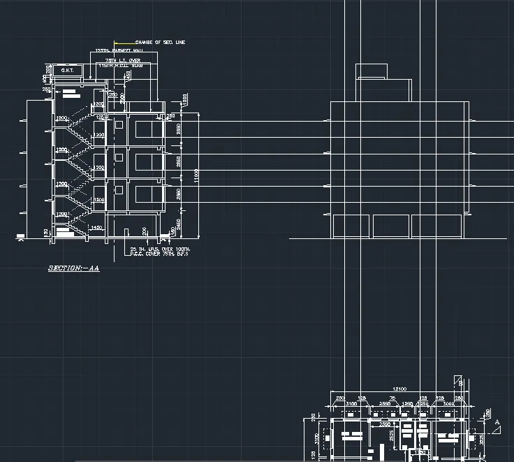
- Type 'LA' in the command line and enter to get layers
- Create a new layer "Windows"
- Type 'RAY' in the command line and enter to get ray tool
- Draw rays of windows from the section-AA and plan
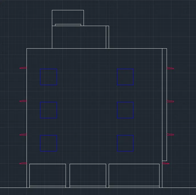
- Type 'TR' in the command line and enter to get trim tool
- Remove all unnecessary lines
4. Draw the window and place it in the elevation
- Type 'REC' in the command line and enter to get rectangle
- Draw a rectangle of size 1750mmx1575mm
- Draw a rectangle of size 1625mmx75mm
- Type 'OFF' in the command line and enter to get offset tool
- Offset 75mm from the bottom line in the y direction
- Offset 50mm from the previous line in the y direction
- Offset 1400mm from the previous line in the y direction
- Offset 50mm from the previous line in the y direction
- Offset 25mm from the leftside line in the x direction
- Offset 75mm from the previous line in the x direction
- Offset 25mm from the previous line in the x direction
- Offset 75mm from the previous line in the x direction
- Offset 50mm from the previous line in the x direction
- Offset 675mm from the previous line in the x direction
- Offset 25mm from the previous line in the x direction
- Offset 25mm from the previous line in the x direction
- Offset 675mm from the previous line in the x direction
- Offset 50mm from the previous line in the x direction
- Offset 25mm from the previous line in the x direction
- Offset 75mm from the previous line in the x direction
- Offset 25mm from the previous line in the x direction
- Type 'TR' in the command line and enter to get trim tool
- Remove all unnecessary lines
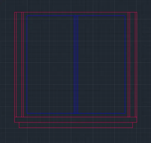
- Type 'L' in the command line and enter to get line
- Draw a line 300mm from upper corner of the left side in the -x direction
- Draw a line 75mm from previous point in the y direction
- Draw a line 300mm from previous point in the x direction
- Draw a line 983.93mm at an angle of 25 degree from previous point in the xy direction
- Type 'MI' in the command line and enter to get mirror tool
- Select the lines and mirror it
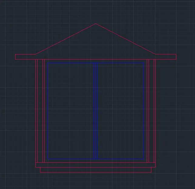
- Type 'POL' in the command line and enter to get polygon
- Draw a triangle of height 460mm and base 1793mm
- Type 'C' in the command line and enter to get circle
- Draw a circle of radius 714mm
- Type 'TR' in the command line and enter to get trim tool
- Remove all unnecessary lines and arcs
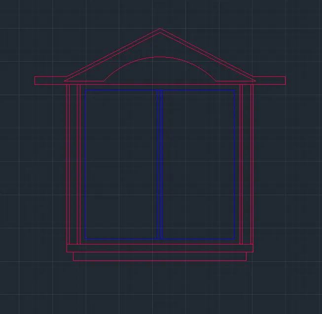
- Type 'CO' in the command line and enter to get copy tool
- Select the window and paste in the elevation
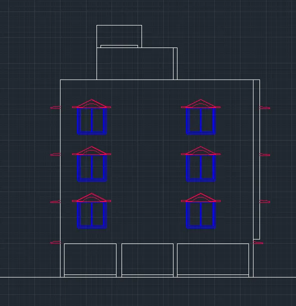
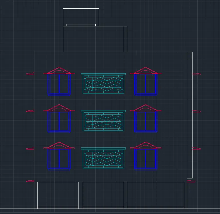
5. Draw the grill in the middle and place it in the elevation
- Type 'LA' in the command line and enter to get layer properties
- Create new layer "Grill"
- Type 'REC' in the command line and enter to get rectangle
- Draw a rectangle of size 3110mmx1450mm
- Type 'OFF' in the command line and enter to get offset tool
- Offset 50mm from the new rectangle inwards
- Offset 150mm from the new rectangle inwards
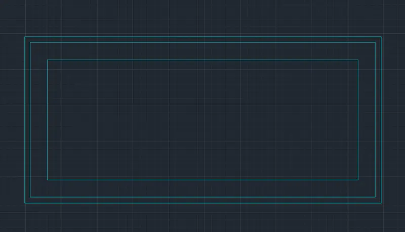
- Select the inner two rectangle and type 'X' to explode
- Type 'OFF' in the command line and enter to get offset tool
- Offset 350mm from middle-left line inwards
- Offset 1150mm from the new line inwards
- Offset 1150mm from the new line inwards
- Offset 350mm from the new line inwards
- Offset 250mm from middle-bottom line inwards
- Offset 850mm from the new line inwards
- Offset 250mm from the new line inwards
- Type 'TR' in the command line and enter to get trim tool
- Remove all unnecessary lines
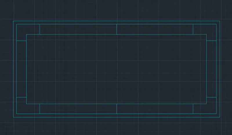
- Type 'OFF' in the command line and enter to get offset tool
- Offset 542mm from the inner-left line inwards
- Offset 542mm from the new line inwards
- Offset 542mm from the new line inwards
- Offset 542mm from the new line inwards
- Offset 262.5mm from the inner-bottom line inwards
- Offset 262.5mm from the new line inwards
- Offset 262.5mm from the new line inwards
- Type 'L' in the command line and enter to get line
- Draw zig-zag lines inside the rectangles of the inner rectangle
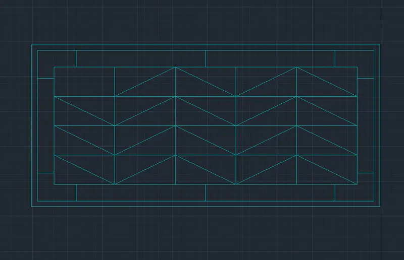
- Type 'REC' in the command line and enter to get rectangle
- Draw a rectangle of size 3390mmx90mm
- Draw a rectangle of size 3390mmx40mm
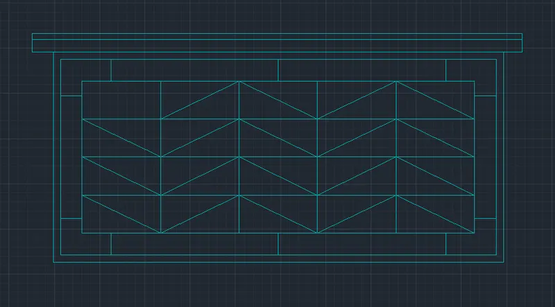
- Type 'CO' in the command line and enter to get copy tool
- Select the grill and paste in the elevation
6. Draw balcony in the elevation
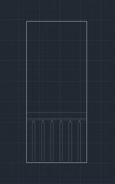
- Type 'REC' in the command line and enter to get rectangle
- Draw a rectangle of size 1000mmx2150mm
- Select the rectangle and type 'X' to explode
- Type 'LA' in the command line and enter to get layer properties
- Create new layer "Rails"
- Type 'OFF' in the command line and enter to get offset tool
- Offset 90mm from the left line inwards
- Offset 15mm from the new line inwards
- Offset 10mm from the new line inwards
- Offset 15mm from the new line inwards
- Offset 100mm from the new line inwards
- Offset 15mm from the new line inwards
- Offset 10mm from the new line inwards
- Offset 15mm from the new line inwards
- Offset 100mm from the new line inwards
- Offset 15mm from the new line inwards
- Offset 10mm from the new line inwards
- Offset 15mm from the new line inwards
- Offset 100mm from the new line inwards
- Offset 15mm from the new line inwards
- Offset 10mm from the new line inwards
- Offset 15mm from the new line inwards
- Offset 100mm from the new line inwards
- Offset 15mm from the new line inwards
- Offset 10mm from the new line inwards
- Offset 15mm from the new line inwards
- Offset 100mm from the new line inwards
- Offset 15mm from the new line inwards
- Offset 10mm from the new line inwards
- Offset 15mm from the new line inwards
- Offset 90mm from the new line inwards
- Offset 650mm from the bottom line inwards
- Offset 25mm from the new line inwards
- Offset 90mm from the new line inwards
- Type 'TR' in the command line and enter to get trim tool
- Remove all unnecessary lines
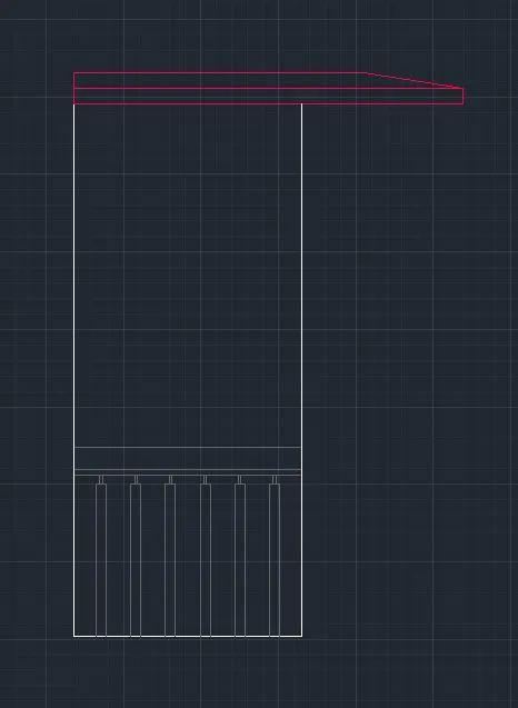
- Type 'L' in the command line and enter to get line
- Draw a line 1570mm from top left corner in the x direction
- Type 'OFF' in the command line and enter to get offset tool
- Offset 60mm from the new line in the y direction
- Offset 60mm from the new line in the y direction
- Type 'L' in the command line and enter to get line
- Draw a line 405mm at an angle of 10 degree from the right end of the middle line in the -x,y direction
- Type 'TR' in the command line and enter to get trim tool
- Remove all unnecessary lines
- Type 'CO' in the command line and enter to get copy tool
- Select the balcony portion and paste in the elevation
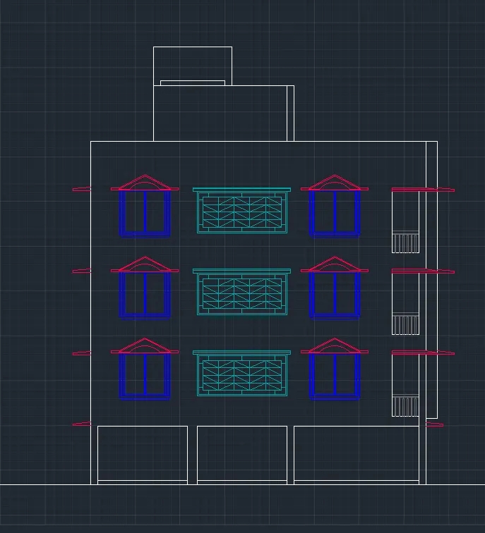
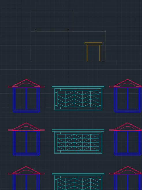
7. Draw the door in the terrace
- Type 'LA' in the command line and enter to get layer properties
- Create new layer "Doors"
- Type 'RAY' in the command line and enter to get ray tool
- Draw rays of windows from the section-AA
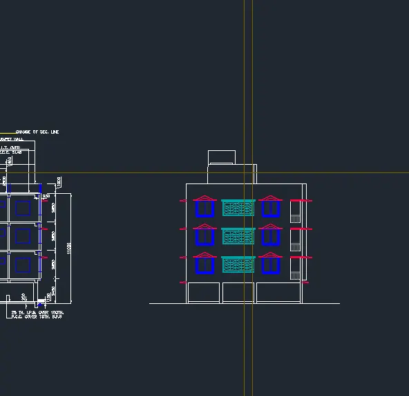
- Type 'OFF' in the command line and enter to get offset tool
- Offset 50mm from the border lines of the door inwards
- Offset 75mm from the top line of the door upwards
- Offset 50mm from the new line upwards
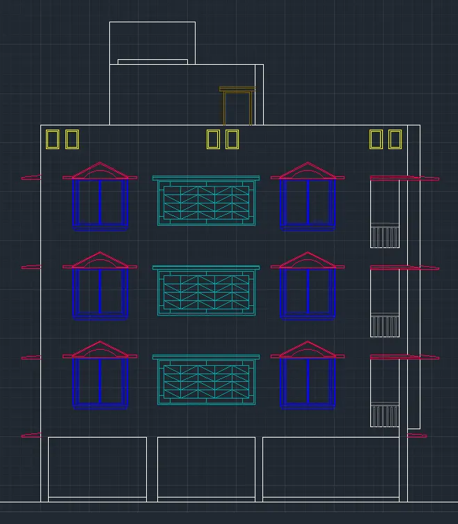
8. Draw the design in the terrace
- Type 'LA' in the command line and enter to get layer properties
- Create new layer "Terrace Design"
- Type 'REC' in the command line and enter to get rectangle
- Draw a rectangle of size 350mmx750mm
- Type 'OFF' in the command line and enter to get offset tool
- Offset 50mm from the rectangle inwards
- Type 'CO' in the command line and enter to get copy tool
- Select the design and paste in the elevation
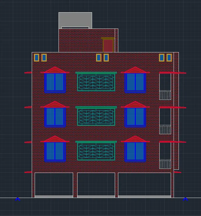
9. Hatching
- Type 'LA' in the command line and enter to get layer properties
- Create new layer "Hatches"
- Type 'H' in the command line and enter to get hatch properties
- Pick internal points: Pick walls (Pattern: AR-BRSTD, colour: 153,27,30)
- Pick internal points: Pick sunshades (Pattern: SOLID, colour: 153,27,30)
- Pick internal points: Pick window frames (Pattern: SOLID, colour: 34,52,110)
- Pick internal points: Pick glasses (Pattern: SOLID, colour: 150, Hatch transparency: 50)
- Pick internal points: Pick rails (Pattern: ANSI36)
- Pick internal points: Pick door frame (Pattern: SOLID, colour: 44)
- Pick internal points: Pick door (Pattern: SOLID, colour: 205,32,39)
- Pick internal points: Pick door grill frames (Pattern: SOLID, colour: 102)
- Pick internal points: Pick floor and tank (Pattern: SOLID, colour: 8)
- Pick internal points: Pick door frame (Pattern: SOLID, colour: 44)
10. Insert texts
- Type 'LA' in the command line and enter to get layers
- Create a new layer "Texts and Annotations"
- Type 'MTEXT' in command line and enter to get text tool
- Type all necessary details as required
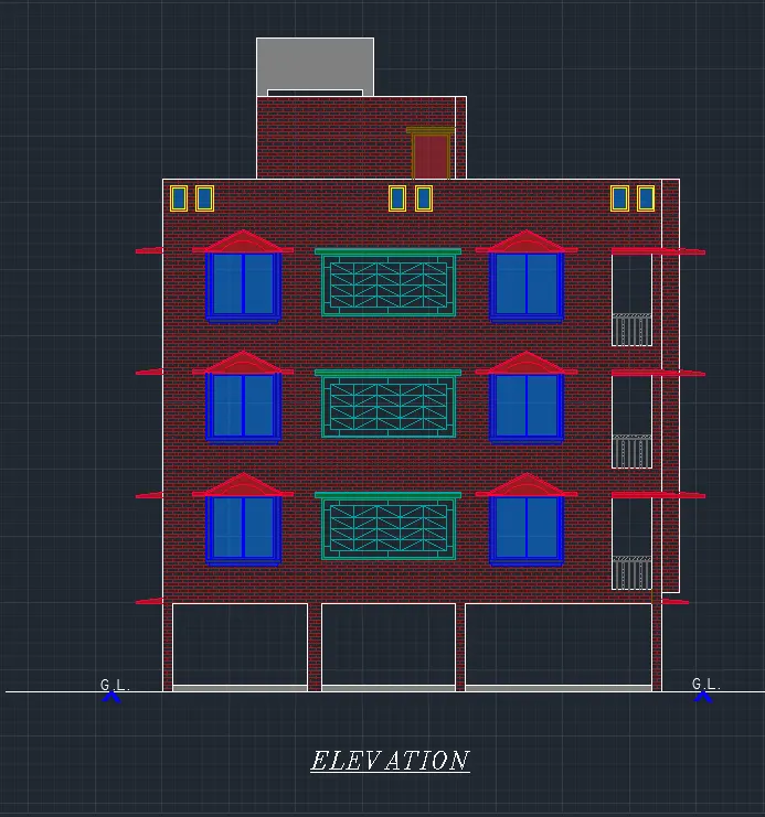
RESULT
The elevation of the plan in the challenge 7 is created and proper hatch in the walls, doors, windows, and other architectural elements is applied.
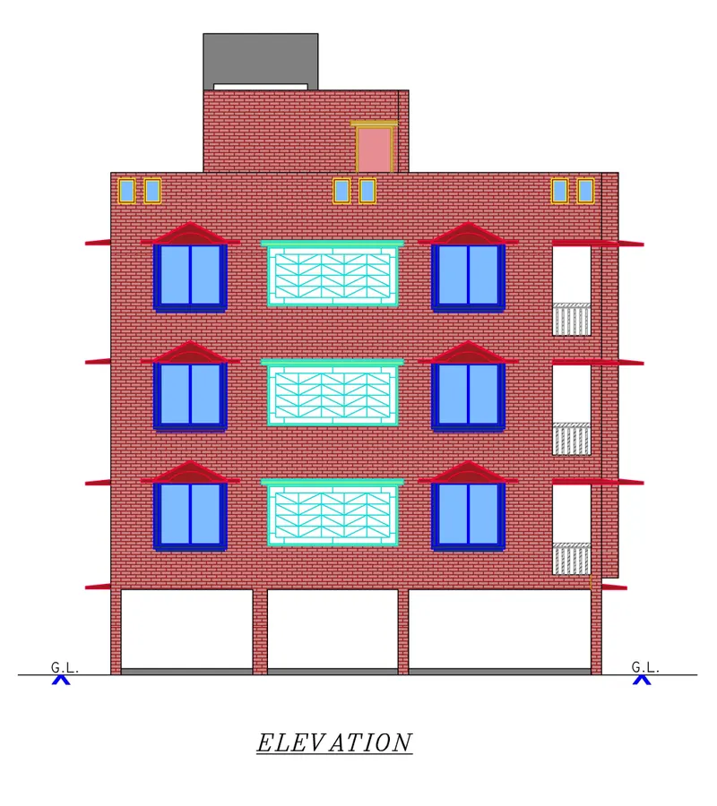
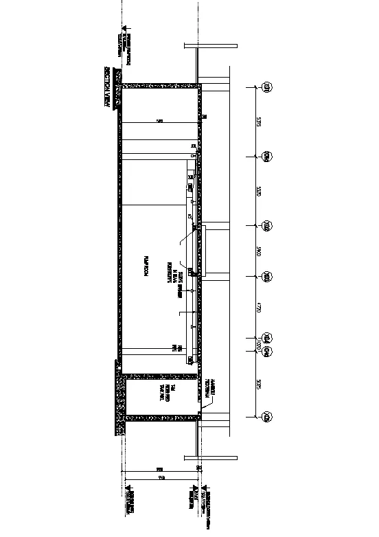
3. Create the section view of an industrial building as shown in Figure. Provide appropriate hatches and dimensions wherever required. Also, provide annotations to the drawing.
AIM
To create the section view of an industrial building as shown in the figure.
INTRODUCTION
The Hatch command in AutoCAD is used to fill patterns inside an enclosed area. The patterns are hatched, gradient, and solid fill. The gradient patterns are defined as a smooth transition between two colors. There are several hatch patterns available in AutoCAD. We can choose the desired pattern from the list of the patterns according to the requirements. The number of hatch lines represented in any pattern can be adjusted with the help of the Hatch Pattern Scale. The Hatch Pattern Scale signifies the spacing between the lines in a particular pattern.
PROCEDURE
Open the AutoCAD Application and create a new AutoCAD file with imperial settings. Set the length type in 'Decimal' and precision (0.00), insertion scale to 'Millimeters' in the Drawing Units and press OK. Set limits and zoom all.
Layers are created, the different layers used in this project is shown below
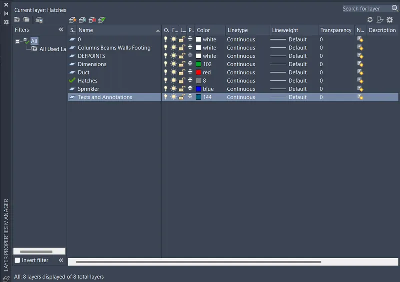
1. Draw the outline of the industrial building
- Type 'LA' in the command line and enter to get layers
- Create a new layer "Columns Beams Walls Footing"
- Type 'XL' in the command line and enter to get xline
- Draw a vertical and horizontal line
- Type 'OFF' in the command line and enter to get offset tool
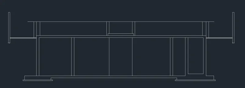
- Offset all necessary lines as given in the figure
- Type 'L' in the command line and enter to get line
- Draw lines as required to complete the drawing, assume missing dimensions
- Type 'TR' in the command line and enter to get trim tool
- Remove all unnecessary lines
2. Draw the duct
- Type 'LA' in the command line and enter to get layers
- Create a new layer "Duct"
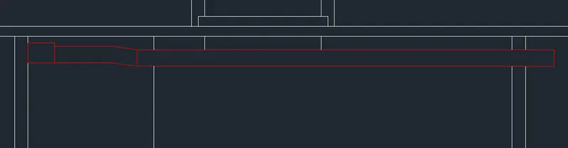
- Type 'REC' in the command line and enter to get rectangle
- Draw a rectangle of 800mx600mm
- Draw a rectangle of 1780mx500mm
- Draw a rectangle 98 degree interior angle of 700mmx500mm
- Draw a rectangle of 12550mx500mm
3. Draw the sprinkler
- Type 'LA' in the command line and enter to get layers
- Create a new layer "Sprinkler"
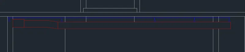
- Type 'REC' in the command line and enter to get rectangle
- Draw a rectangle of 6mmx67mm
- Type 'POL' in the command line and enter to get polygon
- Draw a polygon of 5 side with upper angle 106
- Type 'CO' in the command line and enter to get copy tool
- Select the sprinkler and paste it accordingly
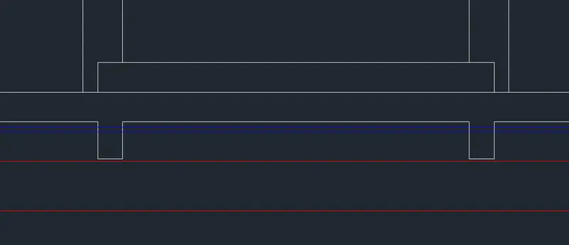
4. Draw the sleeve in beam
- Select "Columns Beams Walls Footing" layer
- Type 'REC' in the command line and enter to get rectangle
- Draw a rectangle of 250mmx375mm
- Type 'CO' in the command line and enter to get copy tool
- Select the beam and place it accordingly
- Type 'TR' in the command line and enter to get trim tool
- Remove all unnecessary lines
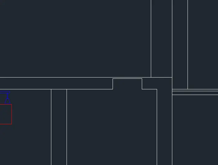
5. Draw the manhole
- Type 'REC' in the command line and enter to get rectangle
- Draw a rectangle of 750mmx270mm
- Type 'TR' in the command line and enter to get trim tool
- Remove all unnecessary lines
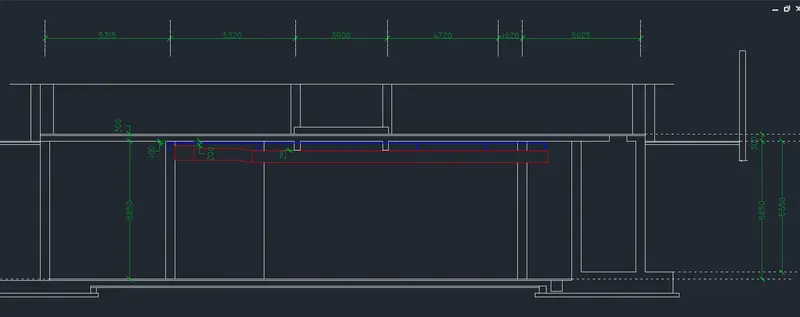
6. Insert dimensions
- Type 'LA' in the command line and enter to get layers
- Create a new layer "Dimensions"
- Type 'DIMSTY' in the command line and enter to get dimension style settings
- Dimension Style is created as New
- In Lines, Fixed length extension lines is given as 100mm.
- In Symbols and Arrows, Arrowhead is given as 'Architectural Tick', Arrow size is given as 200mm.
- In Text, Text height is given as 250mm
- In Fit, Overall scale is given as 1
- Type 'DIM' in the command line and enter to get dimension line
- Mark all necessary dimensions
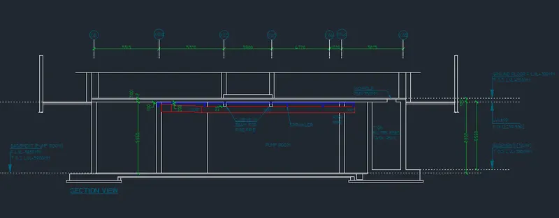
7. Insert texts and annotations
- Type 'LA' in the command line and enter to get layers
- Create a new layer "Texts and Annotations"
- Type 'MTEXT' in command line and enter to get text tool
- Type all necessary details as required
- Type 'C' in command line and enter to get circle
- Draw circle around some text as per the drawings
8. Hatching
- Type 'LA' in the command line and enter to get layer properties
- Create new layer "Hatches"
- Type 'H' in the command line and enter to get hatch properties
- Pick internal points: Pick concrete protions (Pattern: AR-CONC)
- Pick internal points: Pick solid protions (Pattern: SOLID, Colour: Black)
- Pick internal points: Pick square protions (Pattern: ANSI31)
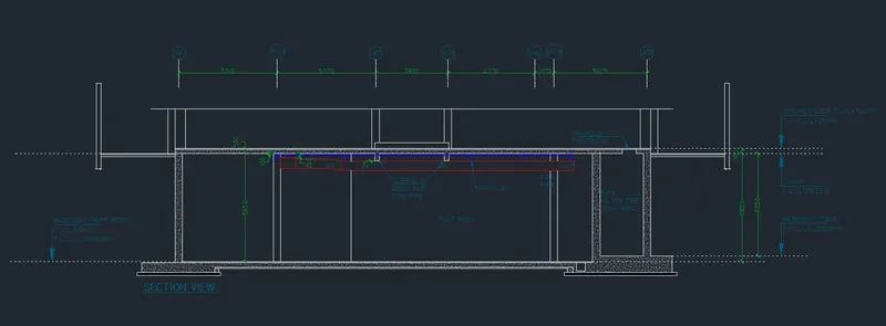
RESULT
The section view of an industrial building is created as shown in figure. All dimensions are in 'mm'. The final result is shown in landscape mode because of the quality of the image