Creating Kitchen layout, Hatching of Architectural elements and sectional view of an Industrial Building in AutoCad
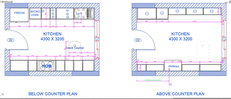
AIM: Create the Kitchen Layout as shown in the Figure below. Also, use proper dimension techniques to dimension the kitchen layout. Also, insert text wherever required. All dimensions are in mm.
PROCEDURE:
STEP-1:
- Select units as a millimeteres and decimals 0.0
- set the limmax as a 100m,100m
- fant style as arial in anotate section.
STEP-2:
- with using line command draw a required as per the dimentions given in the drawing.
- partions made with TRIM,OFFSET and EXTEND command.
- pation thickness given as 20mm and wall thickness is 230mm
RESULTS:
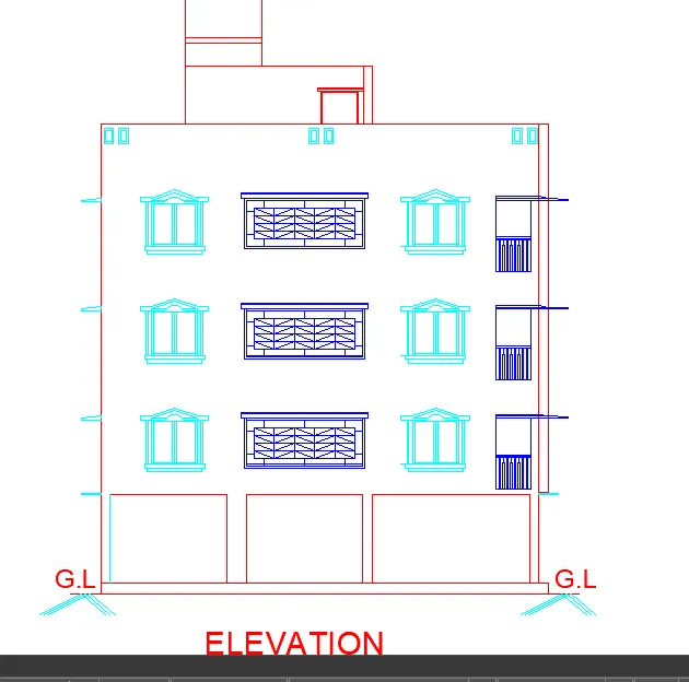
AIM:Create the elevation of the plan created in the Challenges 7 and apply proper hatch in the walls, doors, windows, and other architectural elements. Refer to the dimensions in Plans and sections in Challenges 7.
PROCEDURE:
STEP-1:
- Select units as a millimeteres and decimals 0.0
- set the limmax as a 100m,100m
- fant style as arial in anotate section.
STEP-2:
- Make a copy of that previous challenge no.7 drawings into present sheet.
- after that use command XLINES command draw a lines required portions.
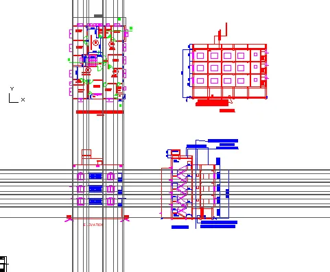
- by this constraction lines use as a reference lines and use it as draw the required element by this both sides element who will replicate items will drawn.
- both the horizontal and vertical lines or reference lines join point as a windows jointion points as a columns , floor height, varnda and sunshade covers to windows.
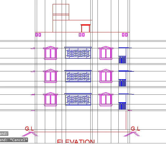
- after completion of drawing erase the xllines are off the layer of xlines.
RESULTS:
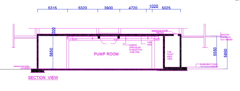
AIM: Create the section view of an industrial building as shown in Figure. Provide appropriate hatches and dimensions wherever required. Also, provide annotations to the drawing.
PROCEDURE:
STEP-1:
- Select units as a millimeteres and decimals 0.0
- set the limmax as a 100m,100m
- fant style as arial in anotate section.
STEP-2:
- Using LINE command draw the require ines as require.
- this drawing related the industrial building .
- the walls about to concrete so concrete hatch provide by using HATCH command.
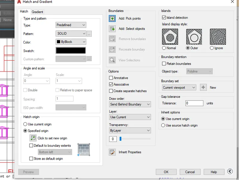
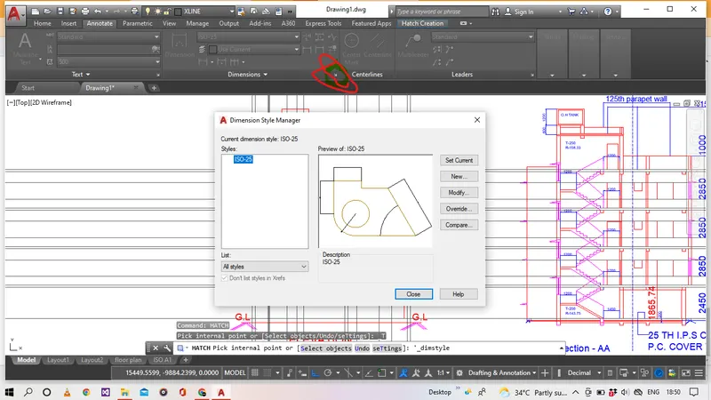
- and dimentions provided in mm decimals so go to annotations< select options<set new dimentions of dimention style manger < set the height of text <as we do custion adjusts like arrow sybols , arrow sizes, break line length and position of text vertical or horizontal make from hear.
- apply text to the drawing through the command of MTEXT or annotation < multitext in that tool bar.
- in this multitext costom adjusts go on be in option of multitext.
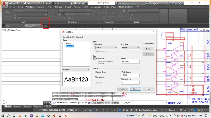
- Upper image i metion red circle use that point as options
- in this window we do custom settings of text.
RESULTS: