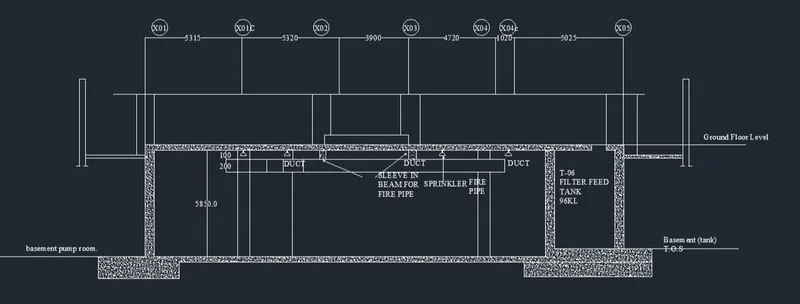
Creating Kitchen layout, Hatching of Architectural elements and sectional view of an Industrial Building in AutoCad
ANS.1.
AIM :-
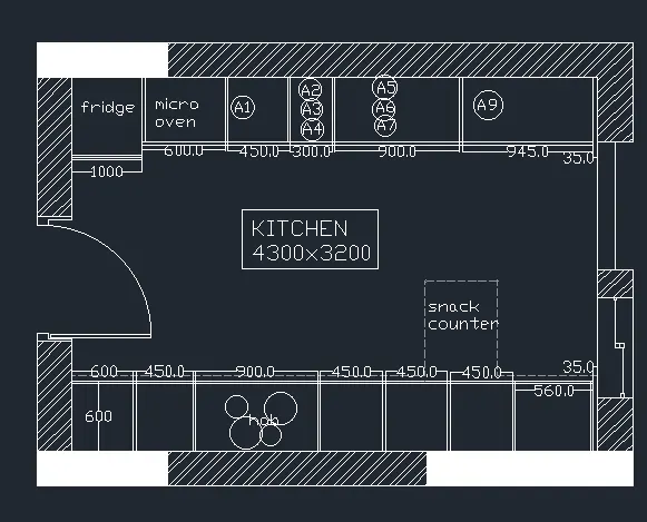
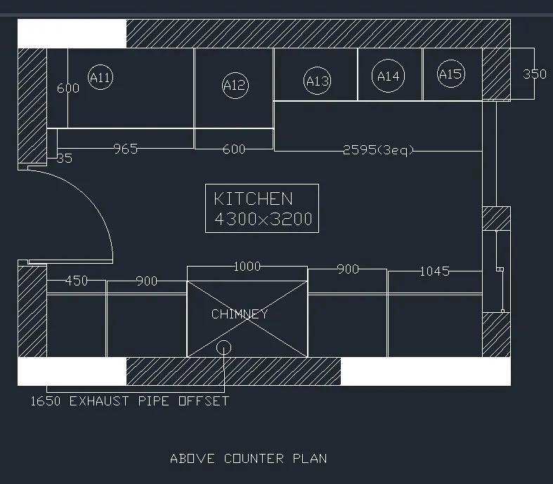
To create the layout of the kitchen and provide hatch pattern as shown in the figure using AutoCAD.
INTRODUCTION :-
Using Autocad software to create the layout of kitchen and also using commands like rectangle move copy trim mirror offset explode etc.
PROCEDURE :-
1. Open the Autocad software and set the limits as 100 , 100 by LIMMAX.
2. Set the units by typing UN in command box and make it in mm.
3. For drawing the below counter plan of kitchen , create offset of 230 around the rectangle.
4. Give offset off 600 from the top of the rectangle to draw the kitchen platform has given in the figure.
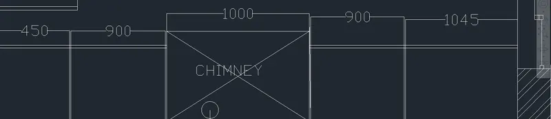
5. Again offset 90 from the left side and from that 1000 for fridge and 600 for micro oven, 450 forA1 , 300 for A2/A3/A4 , 900 for A5, A6,A7 and 300 , 945 and 35 .
6. For creating the bottom, offset 600 from the bottom of kitchen.
7. Then offset again 600 , 450 , 900 , 450 , 450 , 450 , 560 , 35 from the left partof kitchen.
8. Trim the extra lines.
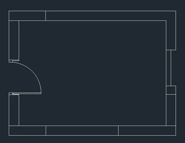
9. For hatching select the hatching pattern as ANSI32 and scale factor as 10.
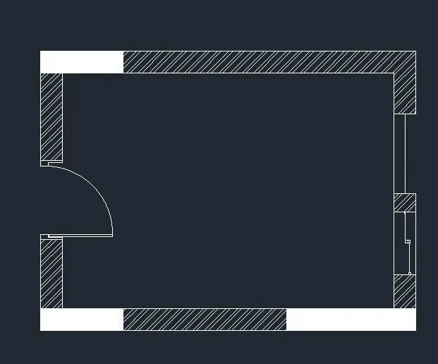
10. To write the text select M text from the tool bar and select the height as 20 and font as txt.shx.
For creating the above counter plan
1. Copy the drawn rectangle without the offset lines and then create ofset of 230 around the rectangle.
2. Offset 600 from the top of the rectangle to draw the platform again and then give the Oxford again from left side 35 as first offset and then offset 965 , 600 , 2595 .
3. Offset 10 to both sides in each corner of the rectangle.
4. Then offset 350 from the bottom to draw the platform of the kitchen.
5. Again offset 450,900,1000,900,1045 .
6. Trim the unwanted lines.
7.For hatching select the hatching pattern as ANSI32 and scale factor as 10.
8. To write the text select M text from the tool bar and select the height as 20 and font as txt.shx.

RESULT :-
Created layout is attached below.
ANS.2.
AIM:-
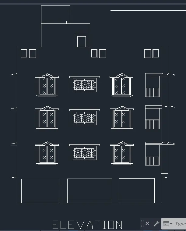
To create elevation of the plan that is created in challenge 7 and to apply proper hatch in the walls doors and windows and other architectural elements
INTRODUCTION:
Using Autocad software to create the layout of kitchen and also using commands like rectangle move copy trim mirror offset explode etc.
PROCEDURE :-
1. Open AutoCAD and then select the line command and after selecting line command extend the lines from the plan in the downward manner to create the projection for the drawing.
2. After that offset 150 mm from the ground level.
3. Then offset 2450 for ground floor , 2850 for first floor , 2850 for second floor , 2850 for third floor , 1000 for paraphet wall.
4. Again offset 2500 from terrace level , 600 and 1200 for overhead tank.
5. Draw the chajjas as per requirements using the line tool.
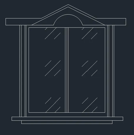
6. To draw the window use rectangle tool to draw it of standard dimensions. Offset as per the requirement of the window.
7. After completing the window drawing draw the stair view using the rectangle and trim tool with line tool in combination as per the created dimensions in challenge 7.
8. Trim the extra lines which are not required.
9. Now for hatching use the glass pattern from the hatching pattern settings and then give the scale factor as 50.
10. To write the text use the M text command with font style as txt. Shx and font height should be 5.
11. Hatch the all window has given in the figure.
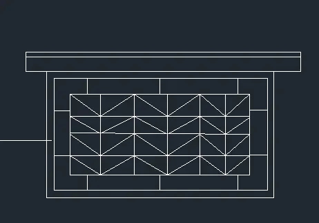
12. Draw the details as given in the figure.
RESULT :-
Created elevation is attached below
ANS.3.:-
AIM :-
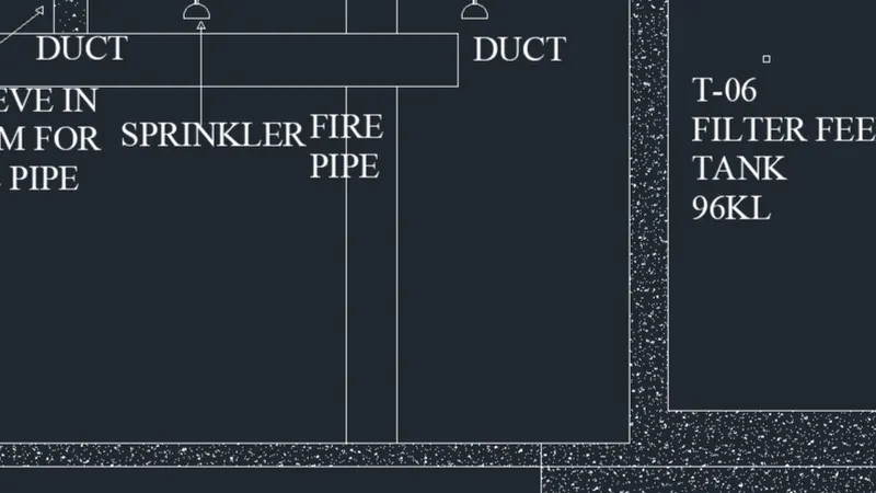
To create the sectional view of an industrial building with providing appropriate hatches and dimensions wherever required and also provide annotations to the drawing.
INTRODUCTION :-
Using Autocad software to create the layout of kitchen and also using commands like rectangle move copy trim mirror offset explode annotations etc
PROCEDURE :-
1. Use the line tool to draw the lines as per the given dimensions of the figure.
2. After drawing the required figure with the given dimensions use the text tool to write the texts.
3. Use dimension tool to dimension the drawn figure. Text height should be 10 and font is time's Roman.
4. To hatch the created figure use the hatch command and then click on the settings to edit the hatch.
5.Use pattern AR-CONC with scale factor of 10 and then select wherever hatching is required.
6. Type LT to change the line type into dotted continuous lines.
7. To draw the circle type c in the command and draw the circles as required

8. Select the dimension tool from the toolbar to dimension the drawn figure.
RESULT :-
Created Sectional view is drawn below :-