Creating Kitchen layout, Hatching of Architectural elements and sectional view of an Industrial Building in AutoCad
Aim: To create the kitchen layout, hatching of architectural elements and sectional view of an industrial building in autocad.
Introduction:
The layout of the kitchen is shows the arrangement of the utensils like fridge, micro oven etc. according to the facing walls of the kitchen space, with corridor and moving soace between them.
The hatch command in the autocad is used to fill the patterns inside an enclosded area. The patterns are hatched, gradient and the solid fill. The gradient pattern are defined as a smooth transition between two colours. There are several hatch patterns available in the autocad. we can choose the desired pattern from the list of the patterns according to the requirements. The number of the hatch lines are represented in any pattern can be adjusted with the help of the hatch.
A sectional view looks inside the objects. sections are used to to clarify the interior construction of a part that can not be clearly by a lines in the plan and elevation. By taking the imaginary cut through the object and removing a portion, the inside features seen more clearly.
Commands Used:
- units command
- limits command
- rectangle command
- line command
- explode command
- offset command
- Dimlinear
- dimcontinuous
- Trim
- Arc
- Dtext
- hatch command
- Move
- Copy
- Block
- Insert command
- X line command
1. Drawing of the kitchen layout
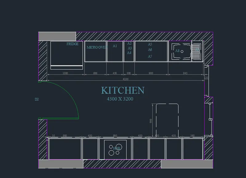
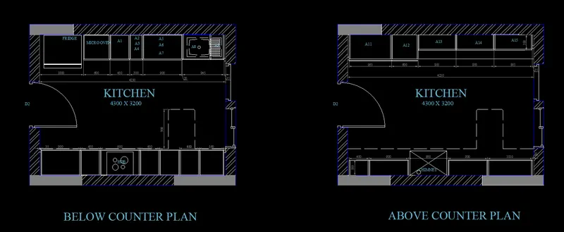
Step 1: Drawing of below counter plan layout
- Open the new sheet select the metric.
- Un Enter select the decimal and precision
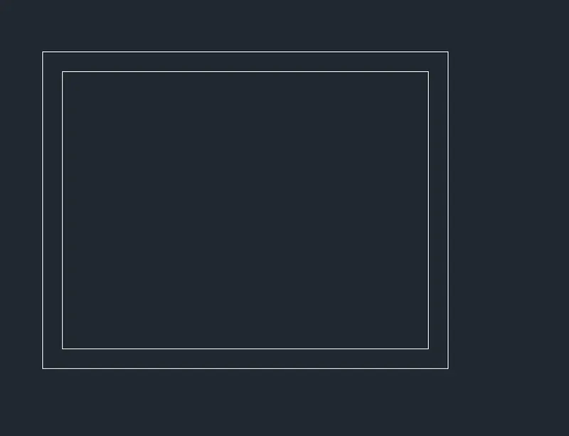
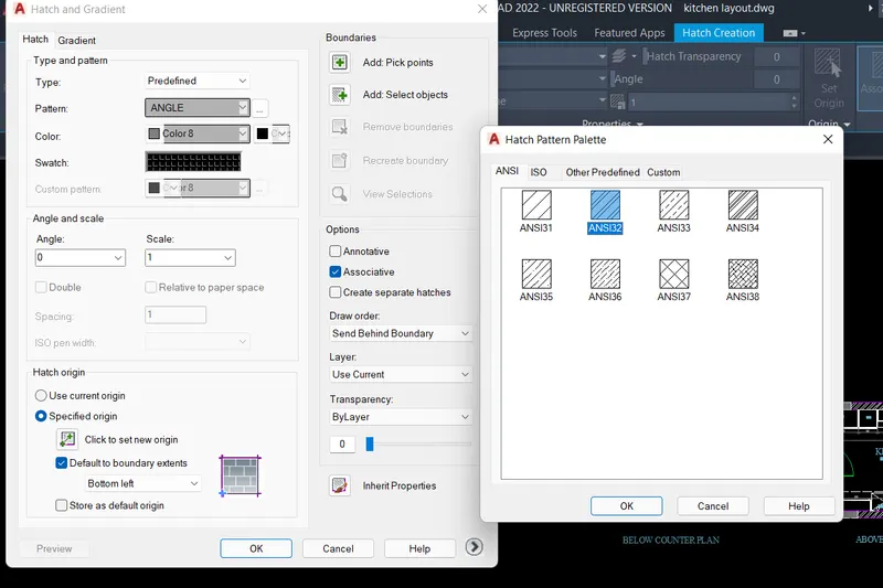
- Draw the rectangular of the size 4300 x 3200 and offset rectangle by a offset distance of 230mm outwards.
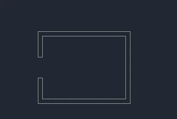
- Explode the rectangle.
- Trim the door opening size of 1100mm.
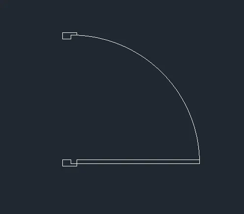
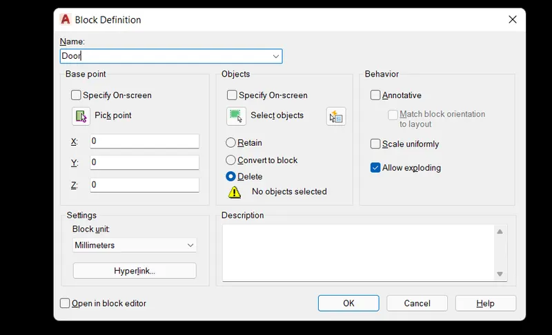
- Draw the door as shown below and it is converted into block.
- The block is inserted at the required position.
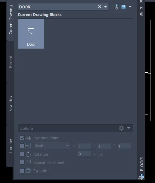
- Offset the kitchen below line by 590mm above and offset on both side by 10mm.
- Select the top line and converted line into acad ISO 02W100.
- Offset the bottom vertical line bt 35mm left side
- Offset the this vertuical line by 900, 450, 900, 450, 450, 450 and 560mm.
- From this offseted vertical line offset 20mm on eitherv side.
- offset the top vertical line by 1000, 600, 450, 300, 900 and 945 respectively.
- Offset the top horizontal line by 570mm downward.
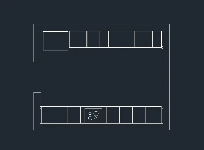
- For the creation of the hatch on the external wall H enter select the setting option the above dialogue box is appeared.
- Select the required hatch pattern from the swatch.
- for the external wall selected the ANSI32 and select the add pick point
- Select the are to be hatched then enter.
- By using the Single line text the text are written.
- By using the dimlinear command the intial dimension given and by using the dimcontinuous other dimensions are given.
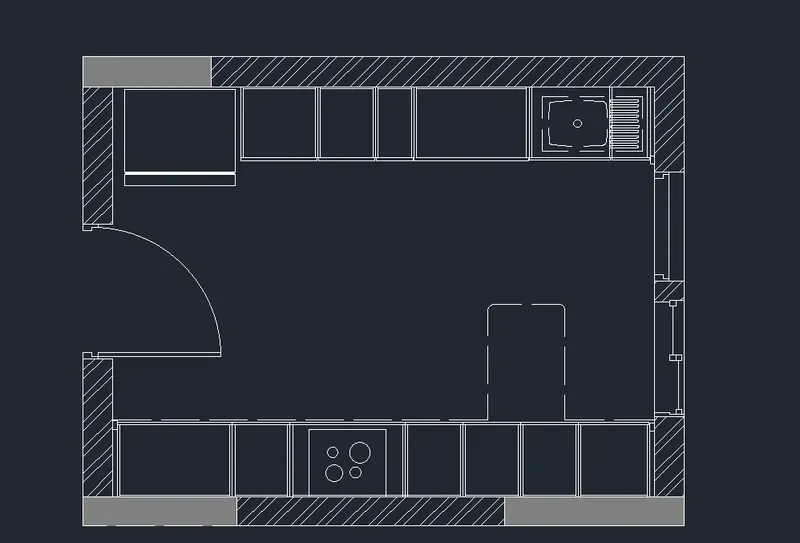
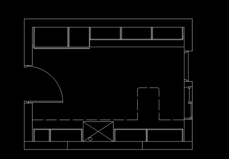
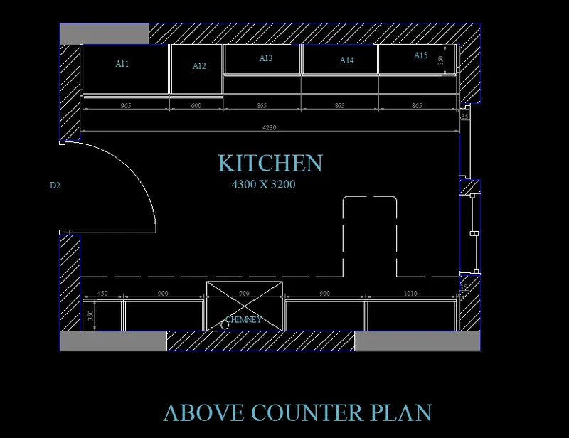
Drawing of the above the counter plan
- Draw the rectangular of the size 4300 x 3200 and offset rectangle by a offset distance of 230mm outwards.
- Explode the rectangle.
- Trim the door opening size of 1100mm.
- The door block is inserted at the required position.
- Offset the kitchen below line by 590mm above and offset on both side by 10mm.
- Select the top line and converted line into acad ISO 02W100.
- Offset the bottom vertical line bt 35mm left side
- Offset the this vertuical line by 450, 900, 900, 900 and 1010mm.
- From this offseted vertical line offset 20mm on eitherv side.
- offset the top vertical line by 35, 965, 600, 865, 865 and 865 respectively.
- Offset the top horizontal line by 350mm downward.
- From this offseted vertical line offset 20mm on eitherv side.
- For the creation of the hatch on the external wall H enter select the setting option the dialogue box is appeared.
- Select the required hatch pattern from the swatch.
- for the external wall selected the ANSI32 and select the add pick point
- Select the are to be hatched then enter.
- By using the Single line text the text are written.
- By using the dimlinear command the intial dimension given and by using the dimcontinuous other dimensions are given.
Result:
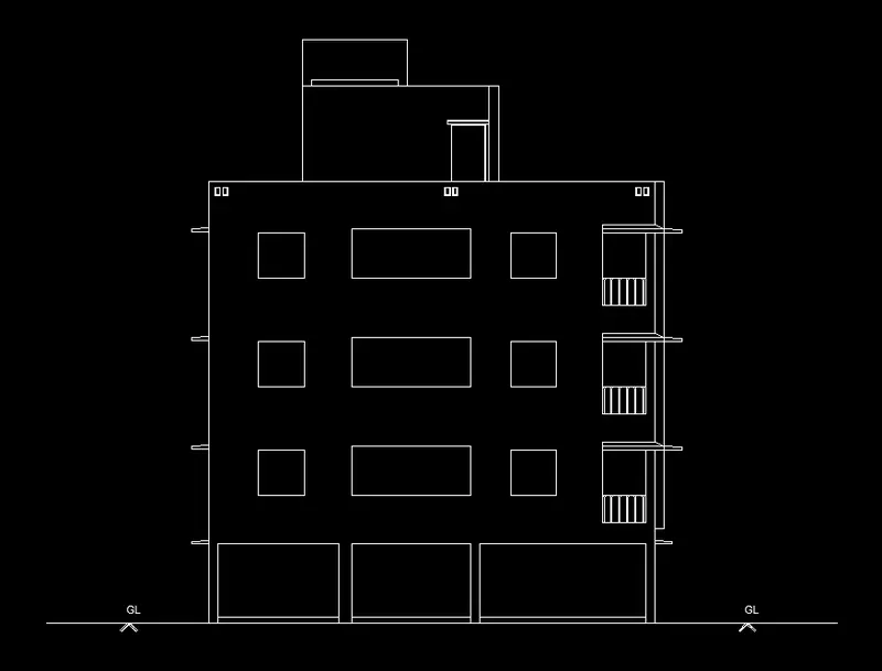
2. Creation of the elevation of the plan drawn on the challenge 7
- Open the plan drawing.
- Extend the lines from the plan downwards by using the xline command.
- draw the horizontal line and offset this line by 2450, 2850, 2850, and 3850mm.
- Offset all these lines by 2100mm upwsrds which is lintel level.
- erase the all slab surface lines.
- Trim the columns lines above the ground floor.
- The lintel level lines are offset below by offset distance of 1200mm and extend lines from the windows from the plan.
- Trim the excess line.
- For the drawing of the OHT extend the lines from the section and lines from the outer wall line of the stair plan, and triiim the unwanted lines.
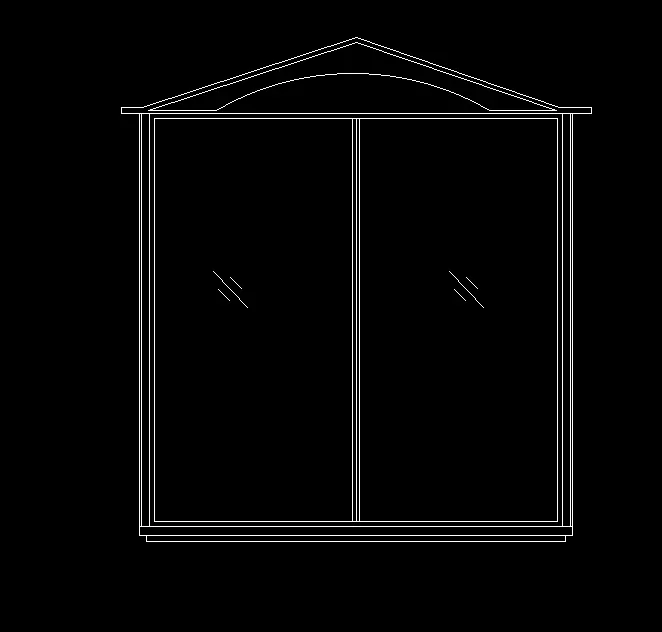
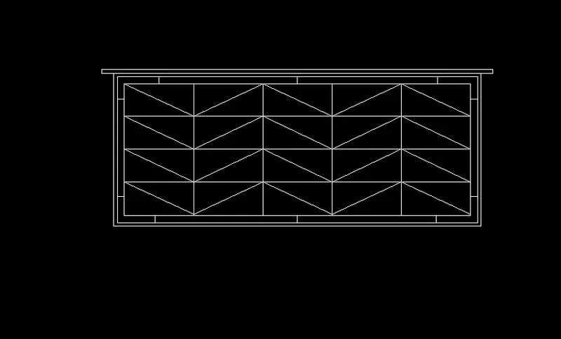
- windows are drawn as shown in below.
- Hatch is created at the windows frame.
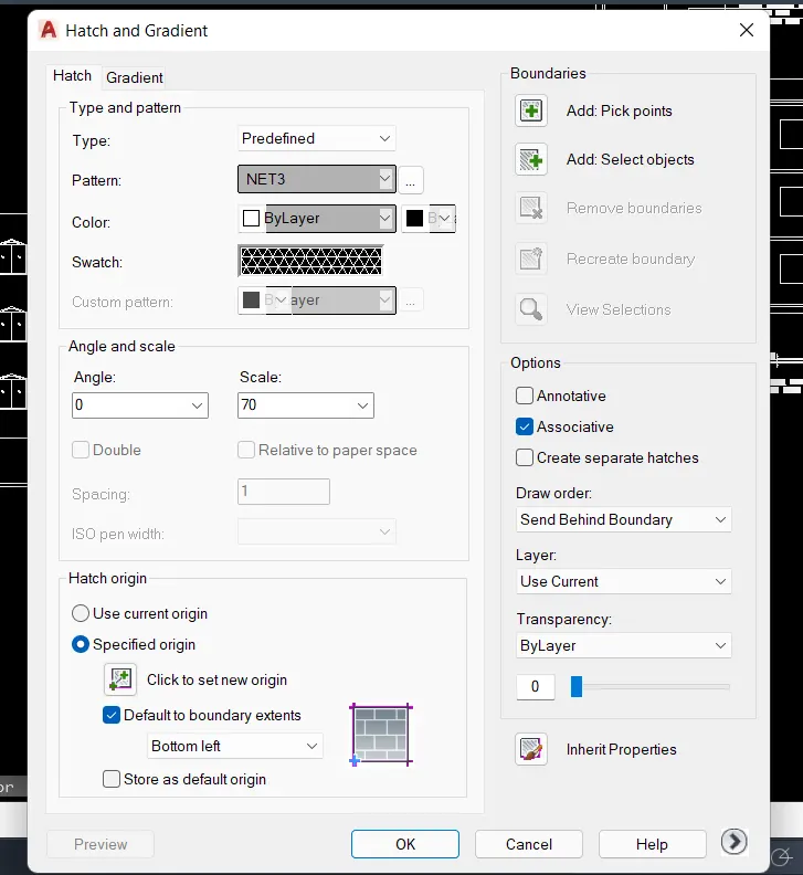
- H enter select the setting and hatch dialogue box is appeared.
- Select the hatch pattern. in this window select ghost glass select the pick point select the closed area that has to be hatched.
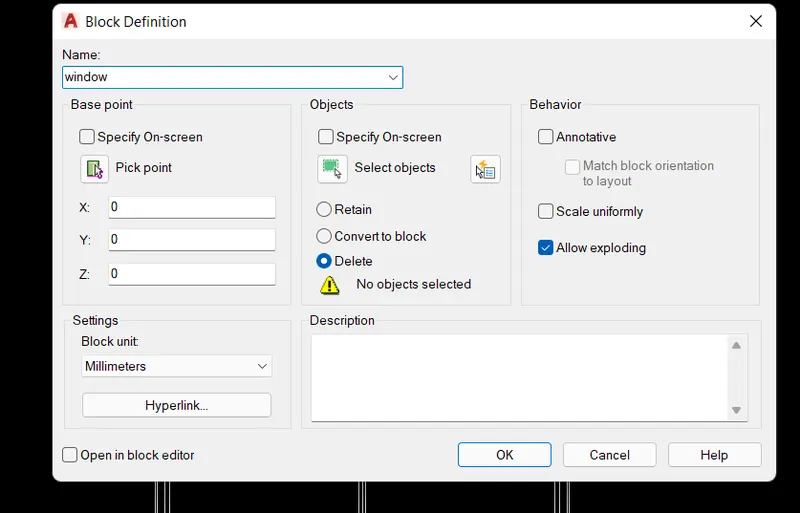
- B enter the block dialogue block will appear and give the name of the block. select the pick up point and select the object.
- By using the insert command the windows block is inserted at required position.
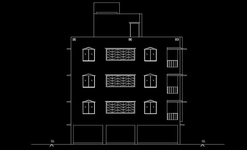
Result:
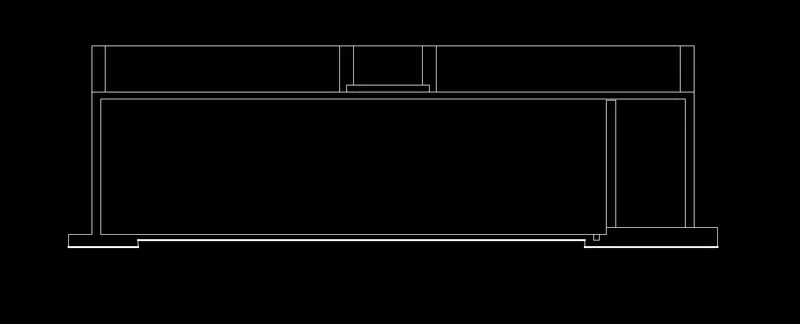
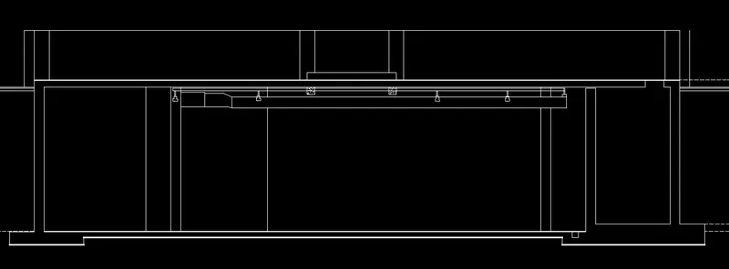
3. Section view of industrial building
- Open the new sheet select the metric.
- Un Enter select the decimal and precision and limmax enter and give the limit value plot area.
- Draw the rectangle of the size 25900 x 6350 mm
- Explode the rectangle.
- From the top corner draw the line of the length of 2000mm upwards.
- offest this line by 300mm rightside.
- offset this line by a offset distance of 5315, 5320, 3900, 4720, 1020 and 5025 respectively.
- From either side offset the line by a offset distance of 300mm.
- Offset the top line of the rectangle by a 300mm downwards. and the left side line by 400mm and bottom line by a 200mm.
- Erase the centre line.
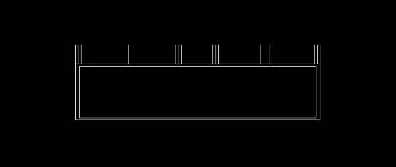
- Offset the rightside vertical line by a offset distance of 3000 on leftside and offset this line by a 400.
- Offset by distyance of 1525mm left side and offset by a 400.
- Left side internal line is offseted by a distance of 5015 right side and this line is offset by a offset distance of 400 mm right side.
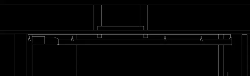
- Duct is created by a distance of 200mm below the top line of the external wall. wuth a duct distance of 450mm.
- Sleeve sprinler are created and converted into the block and inserted at the required position.
- 750mm Manhole are trimmed at the filter feed tank.
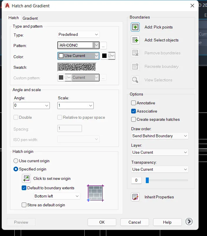
- For the creation of the hatch on the external wall H enter select the setting option the below dialogue box is appeared.
- Select the required hatch pattern from the swatch.
- for the external wall selected the AR CONC and select the add pick point
- Select the area to be hatched then enter.
- By using the Single line text the text are written.
- By using the dimlinear command the intial dimension given and by using the dimcontinuous other dimensions are given.
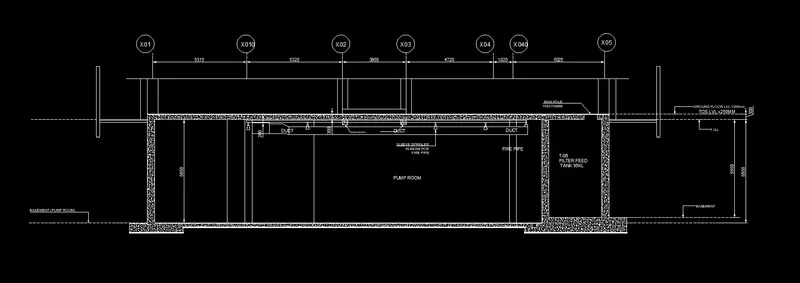
Result: