Creating Kitchen layout, Hatching of Architectural elements and sectional view of an Industrial Building in AutoCad
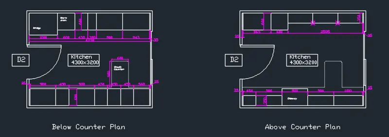
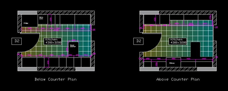
AIM_1: Create the layouts of the Kitchen and provide a hatches pattern as shown. Also, use blocks wherever required. Provide appropriate dimensions in the plan. Assume the size of doors, appliances, and others as per the standards.
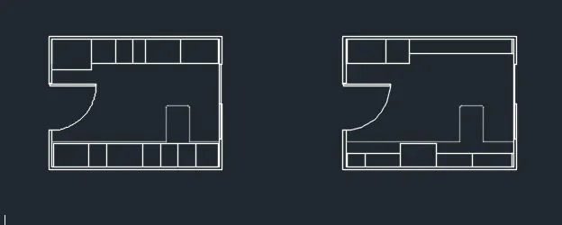
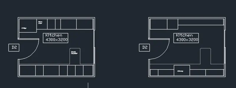
INTRODUCTION: In the given question, the main aim is to make students aware of the hatching commands and use of the blocks. Here in this question, a kitchen layout is drawn using the AutoCAD and hatching is done wherever required. The file is exported from the Challenge 6 project, as it was drawn prior. The first three snips are taken from challenge 6, just to give an idea of how it was drawn.
PROCEDURE:
- Import the whole layout of the kitchen, i.e., the dwd file of challenge 6.
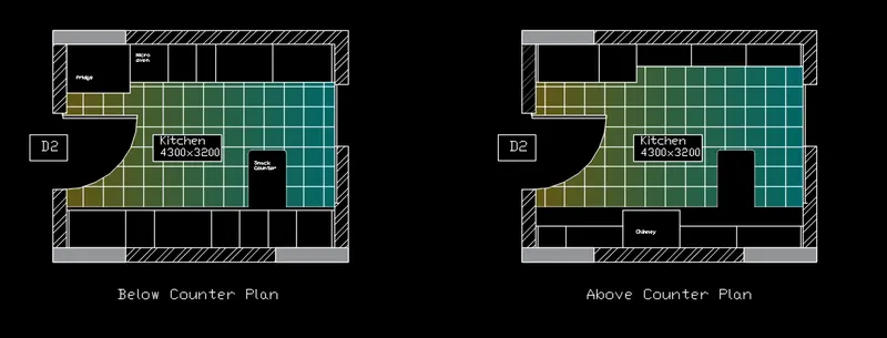
- Now the imported file is hatched using the hatch command.
- The walls are hatched with slant lines, while the columns are hatched in solid color.
- The floor of the kitchen is given two different hatches.
- One is the pattern and the other one is the gradient.
- The snips of the whole procedure are shown below!
RESULTS: The layout of the above and below parts of the kitchen is formed and the layout is then hatched using the advanced hatching tools of the AutoCAD.
SNIPS:
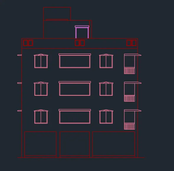
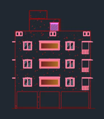
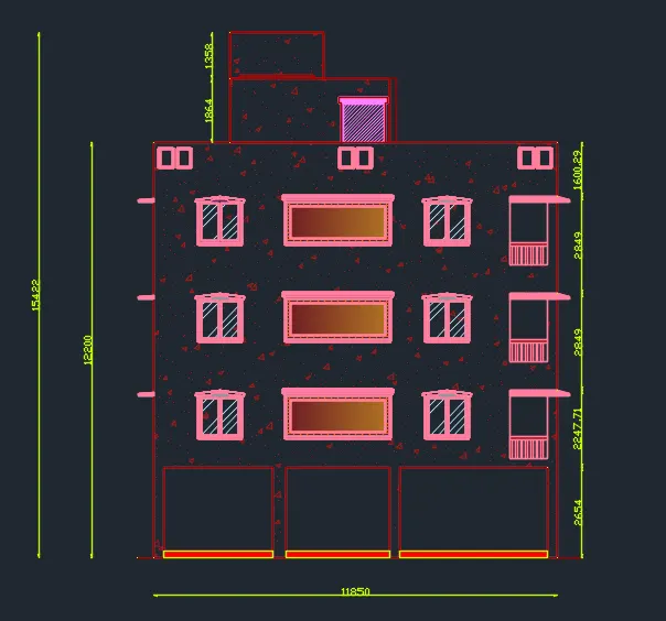
AIM_2: Create the elevation of the plan created in Challenges 7 and apply proper hatch in the walls, doors, windows, and other architectural elements. Refer to the dimensions in Plans and sections in Challenges 7.
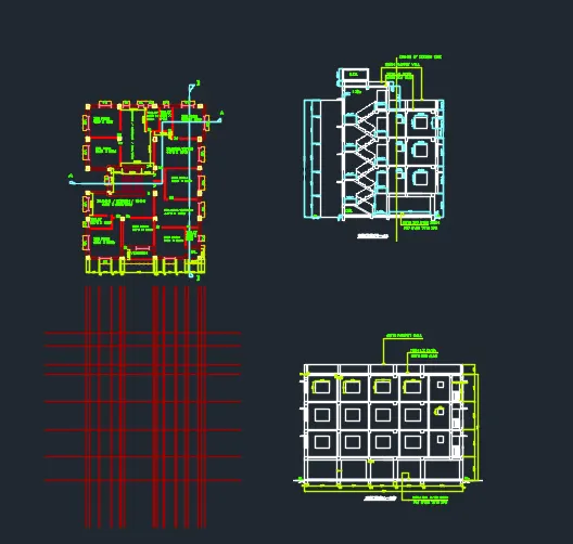
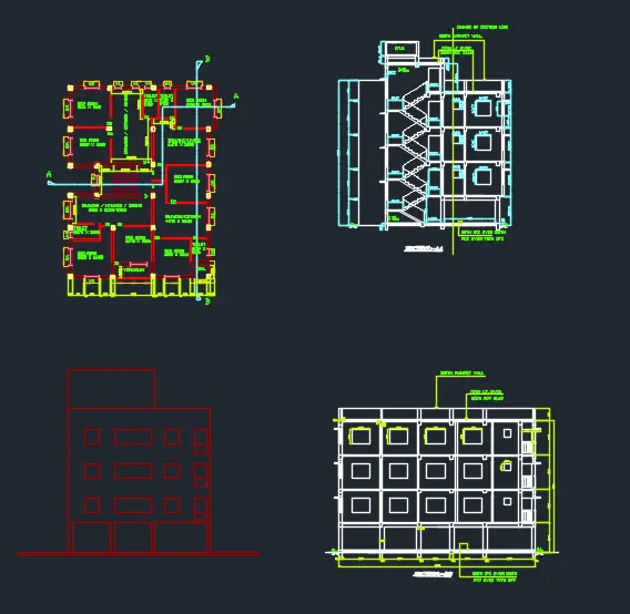
INTRODUCTION: In the following question, the main aim is to draw the elevation of the building which was drawn in challenge 7. This challenge is done to make the students aware of the architectural importance of the elevation of the building. Below is shown the procedure and the results of the elevation. The whole elevation drawing is done in the challenge 7 file itself.
PROCEDURE:
- With reference to the section and the plan of the drawings made in challenge 7, a line diagram is made.
- Now with the help of line, offset, trim and extend commands, the elevation of the building is created.
- Once the elevation is created, now comes the architectural editing.
- Chajjas and railings are drawn to the windows and balconies respectively, using the offset, trim, extend commands.
- Once all the elements of the elevations are drawn, hatching is done.
- Different hatchings are given to the different components of the building.
- Once all the hatching is done, the dimensions and labels are given wherever required.
- Refer to the below snips for more understanding.
RESULTS: The elevation of the building is formed, and hatching is done to it to differentiate all its components.
SNIPS:
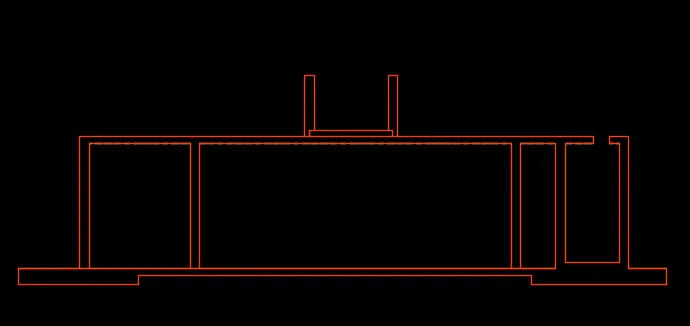
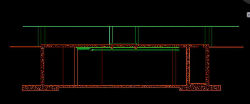
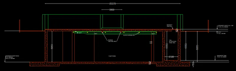
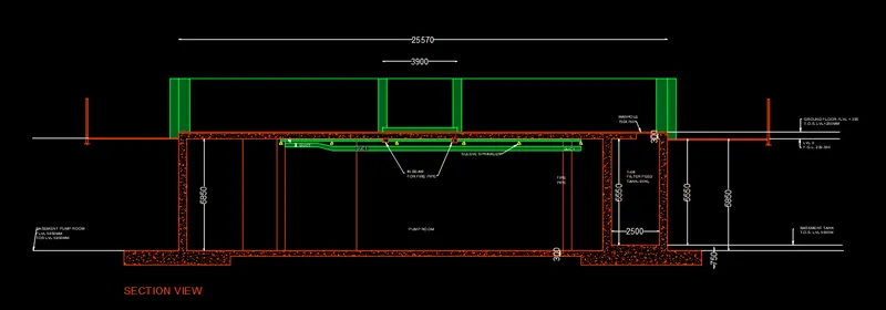
AIM_3: Create the sectional view of the industrial building as shown in the figure. Provide appropriate dimensions and hatches wherever required. Also, provide annotations to the drawing.
INTRODUCTION: In this question, the main aim is to draw the sectional view of an industrial building, and add hatches and annotations to the drawing wherever required.
PROCEDURE:
- A center to center line diagram is drawn, as the dimensions given in the question are center to center.
- Now the offsets of 225mm are given to the centerlines, to draw the columns and pipes.
- All the components are drawn and differentiated in different layers.
- Once all the components are drawn, appropriate hatching is done wherever required.
- Annotations are given.
- Dimensions are given.
- Thus the sectional view of the industrial building is ready.
- Please refer to the below snips for more understanding.
RESULTS: The sectional view of the industrial building is drawn with appropriate dimensions, annotations, and hatching styles.
SNIPS: