Creating Kitchen layout, Hatching of Architectural elements and sectional view of an Industrial Building in AutoCad
Creating Kitchen layout, Hatching of Architectural elements and sectional view of an Industrial Building in AutoCad
Jagadeep.M.M
AIM:
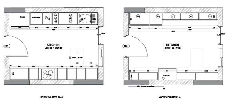
To draw the kitchen layout.
PROCEDURE:
Step 1:
- Open autocad softwere, type QNew incommand box,press enter.
- Select default setting as imperial setting.
- Drawing units setting as length=desimal,precision=0,Insertion scale=Millimeters, Ok
- Drawing limits setting as, specify the lower left corner=enter,upper right corner=4000,4000,enter.
- Type the command box Dimension style manager & press enter.
- enter modify-enter primary units-unit format=desimal, precision=0,enter Ok.
- Zoom command all-enter.
Step 2:
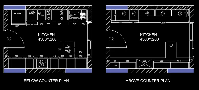
- Draw the below the counter plan:
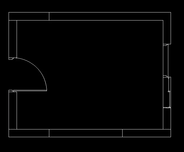
- We create the wall by drawing rectangle of 4300*3200mm & draw offset of 230mm as wall thickness.
- using the arc & line tio create the door,windows.
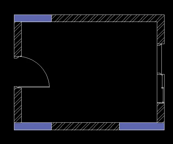
- In the command type the Hatch the drawing.
Step 3:
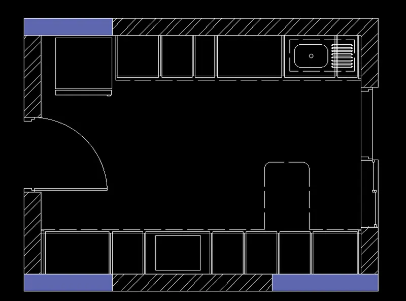
- In the command box type rectangle to draw the dimension of fridge.
- In the command box type offset & offset it to desireed distance to get the micro oven.
- use the trim command to remove the extra line.
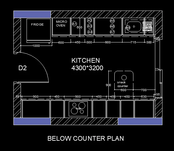
- Now type the offset in command box 1000,600,450,300,900,715,300,35mm hinge.
- give the offset of inside box 20mm.
- take the width of cabinet is 600mm.this is the above the dimensions.
- now draw the below the dimensions.
- Give the 35mm from the left & right side & create a hinge.
- Now type the offset command box give the offset 900,450,900,450,450,450,630mm enter.
- Draw the snack counter by giving offset distance 700mm from the left side of wall & 900mm from the 600mm width of cabinet & fillet with 10mm radius.
- type the dimension using dimension command.
- type the text using text command.
Step 4:
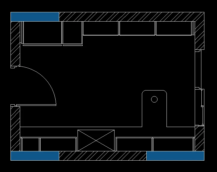
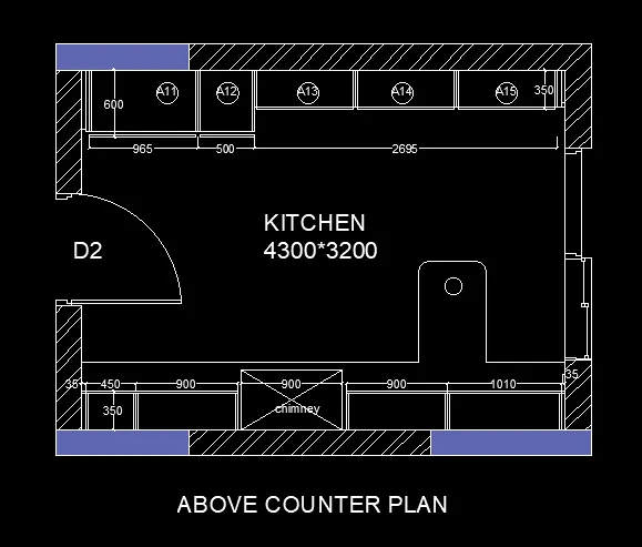
- Draw the Above the counter plan:
- We create the wall by drawing rectangle of 4300*3200mm & draw offset of 230mm as wall thickness.
- using the arc & line tio create the door,windows.
- In the command type the Hatch the drawing.
- In the command box type rectangle to draw the dimension of fridge.
- In the command box type offset & offset it to desireed distance to get the micro oven.
- use the trim command to remove the extra line.
- Now type the offset in command box 35,965,500,give the width of offset is 600mm.
- type the offset in command box give the offset of 2695mm & width is 350mm the 2695mm length divide the 2 segment & join the line.
- give the offset of inside box 20mm.
- now draw the below the dimensions.
- Give the 35mm from the left & right side & create a hinge.
- Now type the offset command box give the offset 450,900,35,900,35,900,1010,35mm enter.
- the chimney width will be 528mm & remaining cabinet willl be 350mm.
- Draw the snack counter by giving offset distance 700mm from the left side of wall & 900mm from the 600mm width of cabinet & fillet with 10mm radius.
- type the dimension using dimension command.
- type the text using text command.
Result:
AIM:
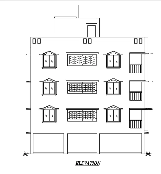
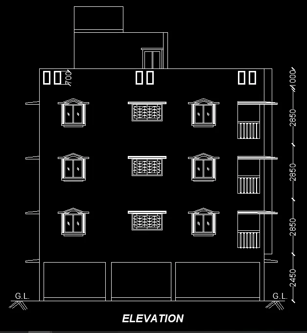
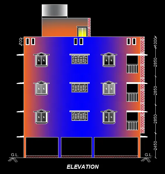
To create the elevation of plan drawn in challeng 7.
PROCEDURE:
Step 1:
- Open autocad softwere, type QNew incommand box,press enter.
- Select default setting as imperial setting.
- Drawing units setting as length=desimal,precision=0,Insertion scale=Millimeters, Ok
- Drawing limits setting as, specify the lower left corner=enter,upper right corner=4000,4000,enter.
- Type the command box Dimension style manager & press enter.
- enter modify-enter primary units-unit format=desimal, precision=0,enter Ok.
- Zoom command all-enter.
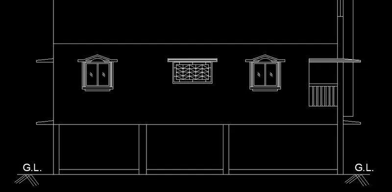
Step 2:
- Open the file of week & where plan is made.
- The command promt enter "XL" & select vertical lines.
- Use the horizontal line with the projection & set the command promt "XL".
- Create the window as the size of 1000mmX1000mm.
- Give the inside offset of 50mm & divide the it give the offset of two side 25mm.
- Then delete the middle line.
- Give the offset in left side 25mm in three times height will be 1023mm. again give the offset of 50mm & mirror the right side also.
- draw the rectangle in bottom side size will be 1250mmX80mm.again give the rectangle 1000mmX80mm.
- Draw the center line in the top,create the line length will be 800mm,give the offset above 50mm.
- draw the slop at 20 degree to connect the cenetr line.
- draw the arc & mirror the right side.
Step 3:
- Copy the elevation in two times above plan.
- The sun shade at the edge of the wall on the both sides.copy it in the above floor.
- above the floor plan draw the head tank.
- Insert the text using text command.
- Insert the hatch using hatch command.
Result:
AIM:
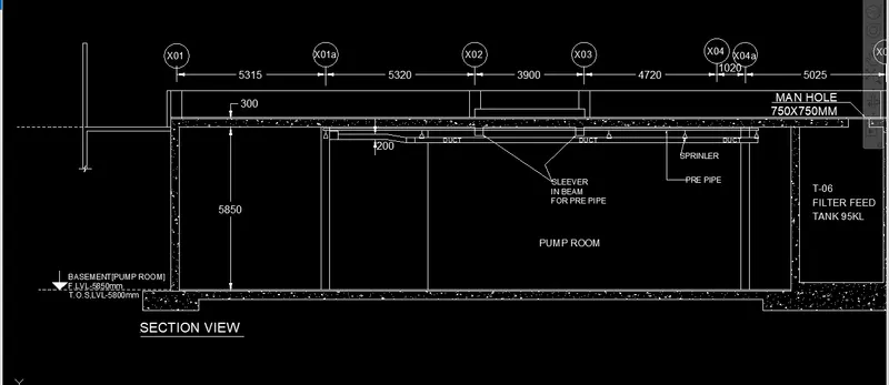
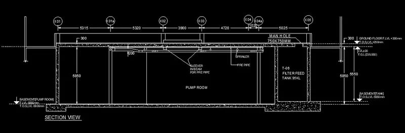
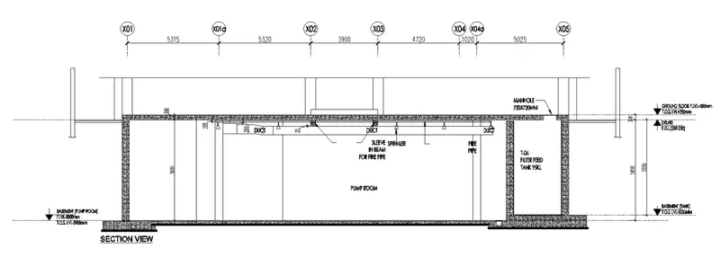
To Draw the section view of industrial building plan hatching it using AUTOCAD.
PROCEDURE:
Step 1:
- Open autocad softwere, type QNew incommand box,press enter.
- Select default setting as imperial setting.
- Drawing units setting as length=desimal,precision=0,Insertion scale=Millimeters, Ok
- Drawing limits setting as, specify the lower left corner=enter,upper right corner=1000,1000,enter.
- Type the command box Dimension style manager & press enter.
- enter modify-enter primary units-unit format=desimal, precision=0,enter Ok.
- Zoom command all-enter.
Step 2:
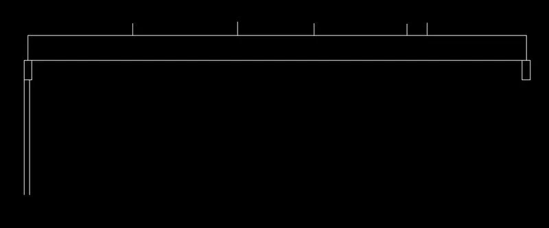
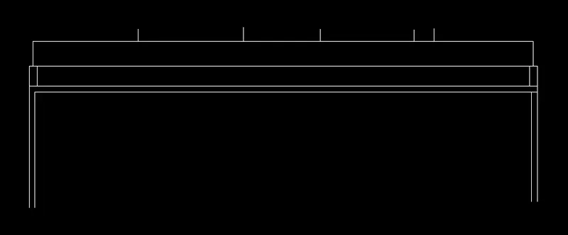
- Draw the line in Y direcion 5850mm & offset it 300mm.
- Draw the above line 300mm & Draw the X direction in right side.
- Give the offset of below the line 300mm.
- type the rectangle above the 300mm first point draw the rectangle as @300,1000mm.
- Draw the rectangle middle line also & give the offset distance in right side as 5315,5320,3900,4720,1020,5025mm.
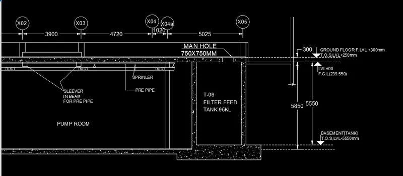
- Mirror the left side wall drawing in right side ,the height of wall will be 5550mm.
Step 3:
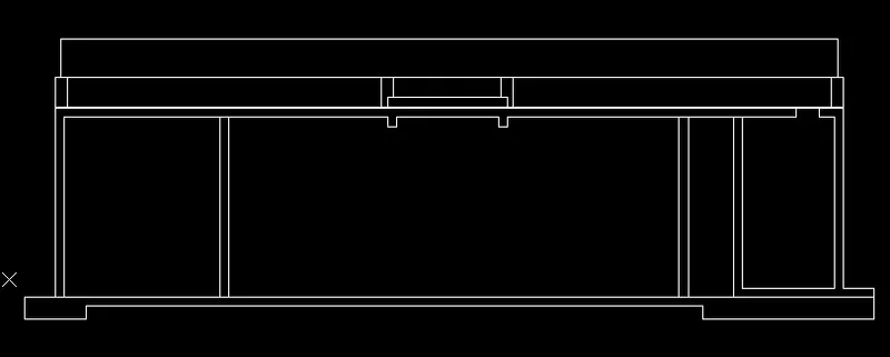
- Wherever line required draw the line.
- Draw the bottom foundation left side distance 1000mm & -y direction 700mm,+x direction 2000mm +y direction 400mm & draw the stright line X direction.
- The above length distance are given that will be extand it.
- Draw the filter feed tank length are 3000mm inner distance & give the offset of 300mm in left side.
- trim the unwanted line.
Step 4:
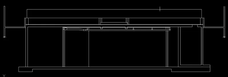
- Draw the manhole length will be 750mm.
- Create the duct height is 200mm.
- Draw the sleeve in beam for pre pipe.
- Draw the sprinler.
Step 5:
- Give Text using text command.
- Give the dimension using dimension command.
- give the leader using leader command.
- Give the hatch using hatch command
Result: