Creating Kitchen layout, Hatching of Architectural elements and sectional view of an Industrial Building in AutoCad
Creating Kitchen layout, Hatching of Architectural elements and sectional view of an Industrial Building in AutoCad
1. AIM:
To draw the kitchen layout as shown in figure using AutoCAD software and explain the procedure step by step to obtain the result.
INTRODUCTION:
AutoCAD is a computer aided design software and drafting software application.
In this project, i have used various commands like,
* Line, XLine (horizontal and vertical), Polyline, Circle - to create the plan, windows, doors.
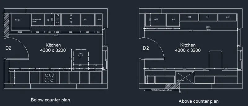
* Dtext - to mention the texts.
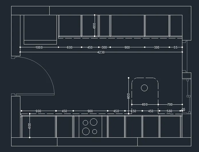
* Commands DIM Linear, DIM Continue - to create the Dimension lines.
* LAYERS - created individual layers for Plan, Dimensions, and texts.
* Blocks - To create doors, window and ventilaton.
* Hatch - ANSI32 and solid fill used for walls.
* Fillet, Trim/erase, Offset, ED - are regularly used at various places to complete the diagrams.
In the next step, the procedure is explained perfectly.
PROCEDURE:
- Open AutoCAD software
- Start from scratch
- Set the units to decimal and select ok
- Set limits as lower left corner (0,0) and upper right corner (10000,10000)
- Import the drawing pdf to AutoCAD to check the dimensions and start the drawing as per the given data.
- Go to layer properties < create new layers < name the layers for reference < close
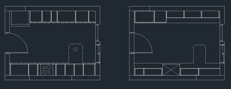
- Using the XLine command (Horizontal and vertical), draw the boundaries for the kitchen plan and mark the door and window spaces also.
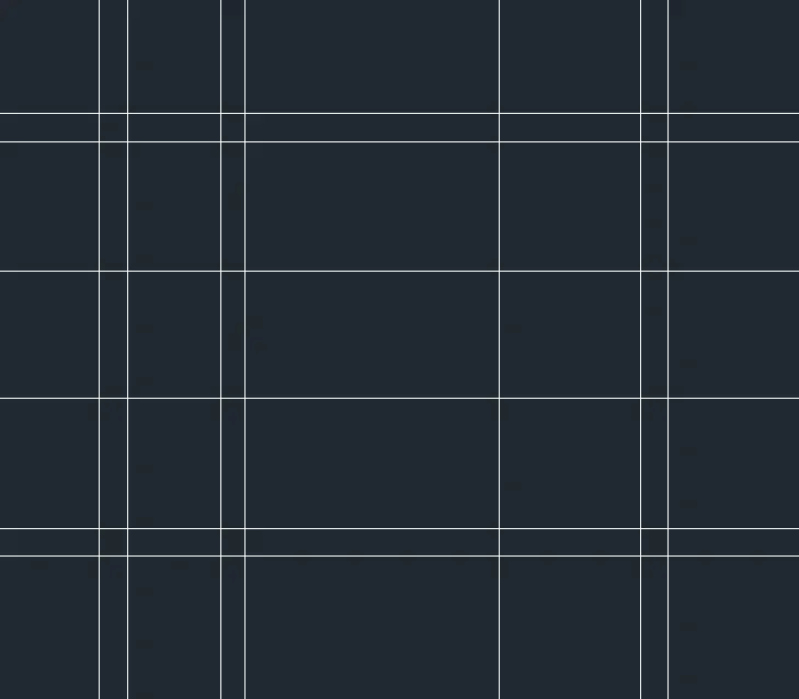
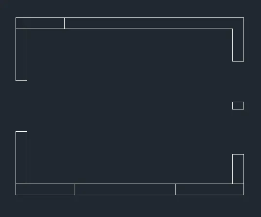
- Using Fillet and Trim Command, cut the lines as per the dimensions to form a kitchen plan.
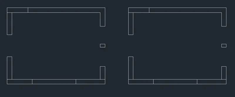
- Using Copy command, copy the same to draw above counter plan.
- Using the commands, line,polyline, and arc, the doors and windows are created separately.
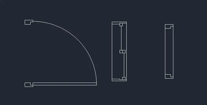
- Using Block definition, the door, window and ventilation are created as separate blocks.
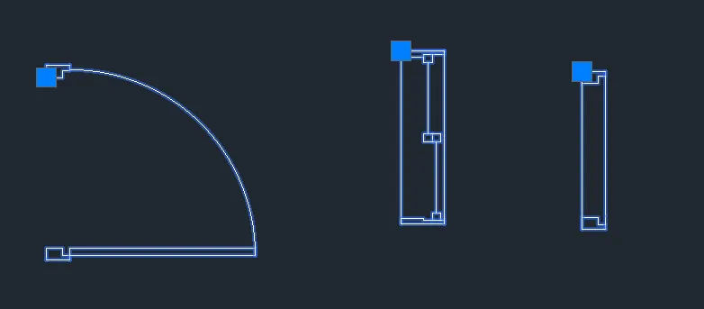
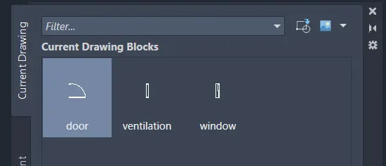
- Using the insert command, insert the doors and windows and place it in their spaces as per the diagram.
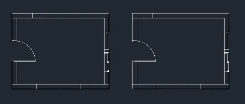
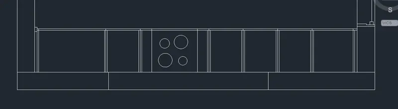
- Using the XLine, fillet and trim commands, the kitchen interior objects are created.
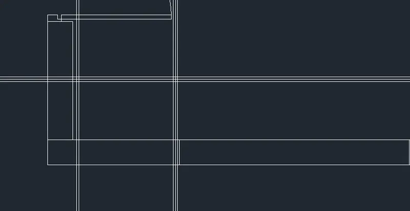
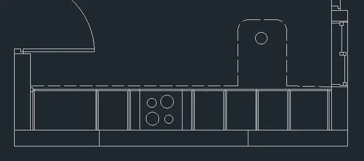
- The short dash line is chosen to draw the snack area.
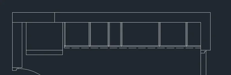
- Using the XLine, fillet and trim commands, the kitchen interior objects are created.
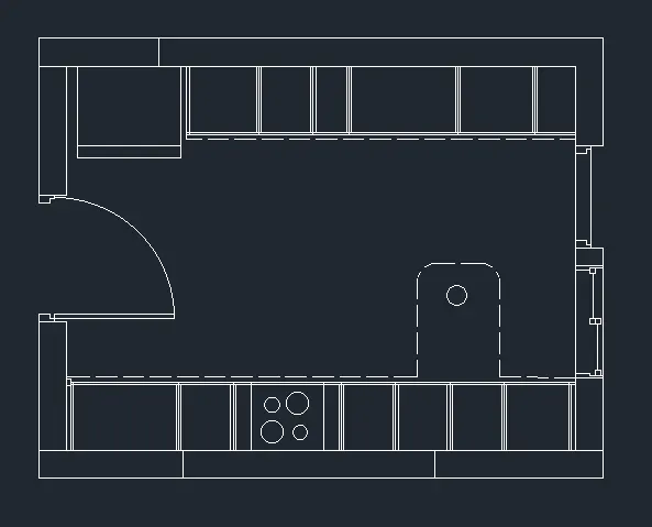
- Using the commands, DIM Linear and DIM Continue, the dimensions are marked for each objects created.
- Using the command DText, the texts are mentioned.
- Using the Hatch command, Hatch - ANSI32 and Solid fill is used to fill the wall.
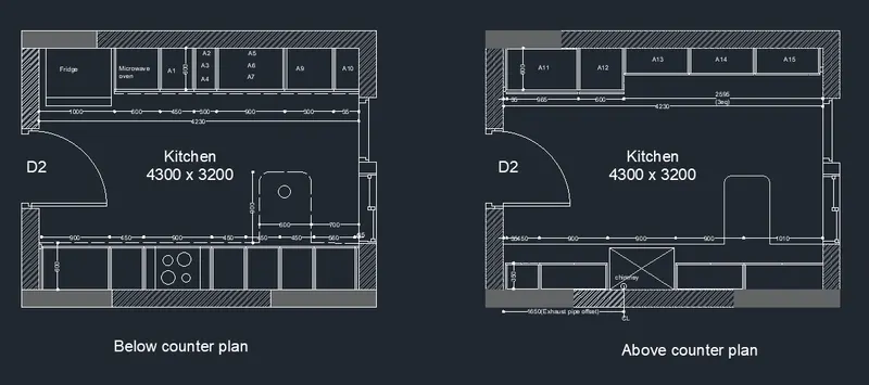
RESULT:
2.
AIM:
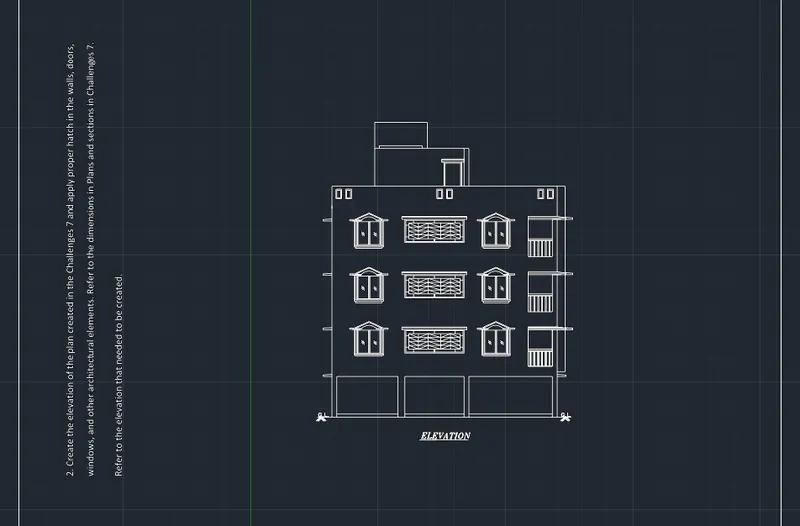
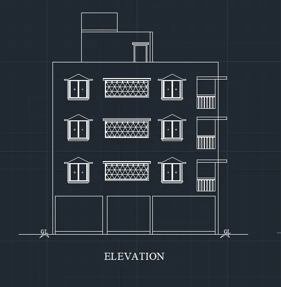
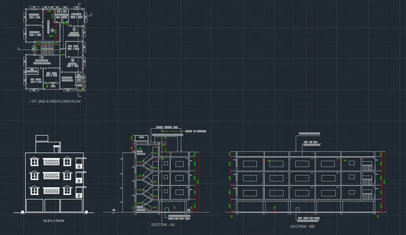
To draw the ELEVATION as shown in figure using AutoCAD software and explain the procedure step by step to obtain the result.
INTRODUCTION:
AutoCAD is a computer aided design software and drafting software application.
In this project, i have used various commands like,
* Line, XLine (horizontal and vertical), Polyline, Circle - to create the plan, windows, doors.
* Dtext - to mention the texts.
* LAYERS - created individual layers for Plan, Dimensions, and texts.
* Blocks - To create doors, window and ventilaton.
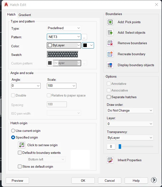
* Hatch - Used NET3 Hatch pattern for design in the center as shown in the diagram.
* Xref - to refer the previous challenge plan into this drawing.
* Fillet, Trim/erase, Offset, ED - are regularly used at various places to complete the diagrams.
In the next step, the procedure is explained perfectly.
PROCEDURE:
- Open AutoCAD software
- Start from scratch
- Set the units to decimal and select ok
- Set limits as lower left corner (0,0) and upper right corner (10000,10000)
- Using XREF Command,
Attach the challenge 7 drawing to the current drawing file to check the dimensions and start the drawing as per the given data.
- The following pictures shows the steps involved in external referencing a drawing file.
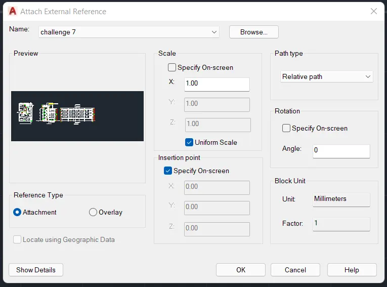
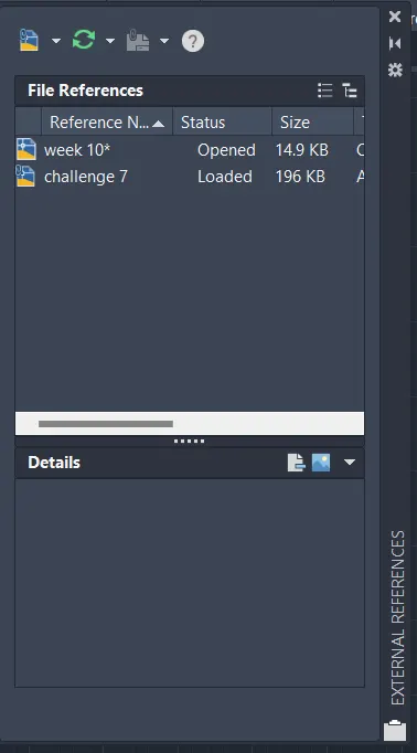
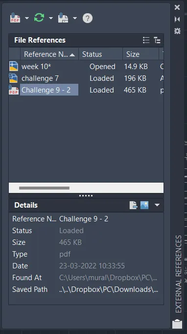
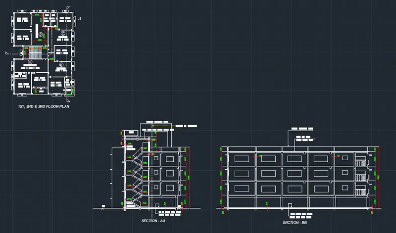
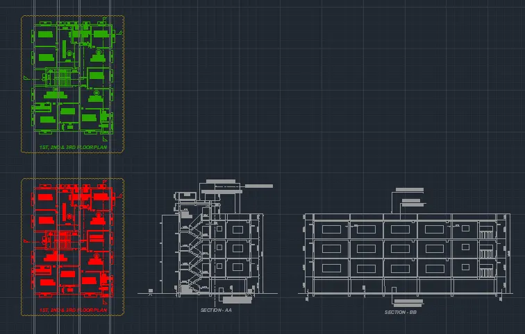
- The Following image shows the XREF drawing in the current drawing.
- Next image is the Xref PDF attached to the current drawing for reference.
- Now, I have made some changes in the reference drawing for my convenient.
- After saving the changes, the current indicates XREF was modified and needs reload.
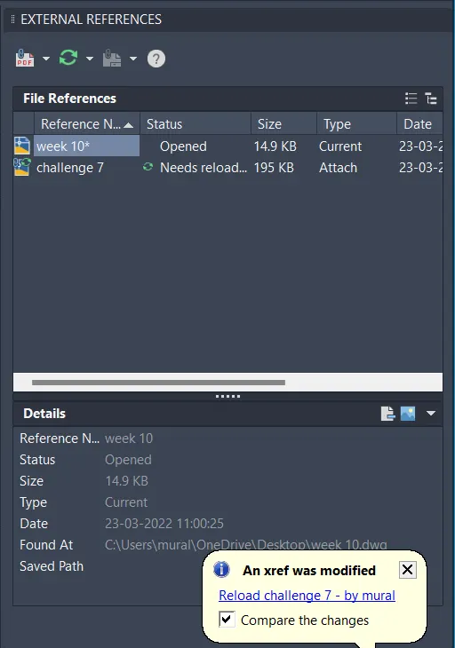
- The following image shows the changes happened in the XREF drawing and needs reload.
- After reloading, i have utilised that space for drawing elevation.
- Using XLINE COMMAND (vertical and Horizontal),
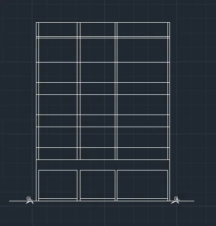
The Columns, Floors , windows and all levels are marked for drawing Elevation for the plan.
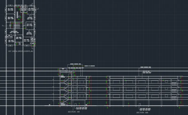
- All the extra lines are trimmed and formed a boundary for the elevation.
- Using Hatch Command, Pattern NET3 type is used in the middle as shown in the diagram.
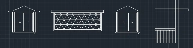
- The following image shows the completed hatch pattern and windows and balcony.
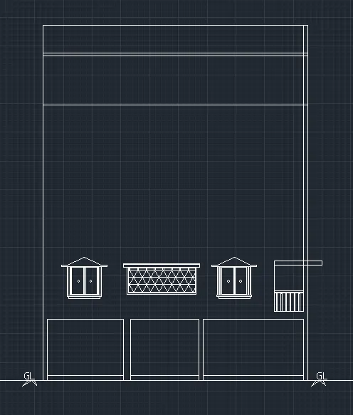
- Using copy command, Copied the same at all Floor levels.
- The staircase room and overhead tank is also completed as shown in the diagram.
RESULT:
3.
AIM:
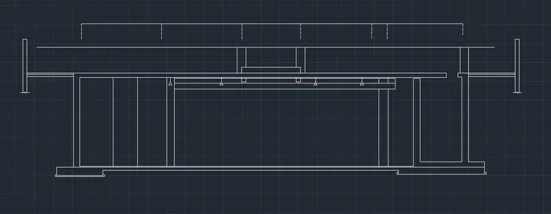
To draw the INDUSTRIAL SECTION as shown in figure using AutoCAD software and explain the procedure step by step to obtain the result.
INTRODUCTION:
AutoCAD is a computer aided design software and drafting software application.
In this project, i have used various commands like,
* Line, XLine (horizontal and vertical), Polyline, Circle - to create the plan, windows, doors.
* Dtext - to mention the texts.
* LAYERS - created individual layers for Plan, Dimensions, and texts.
* Hatch - Used AR-CONC Hatch pattern for concrete walls.
* Xref - to attach the PDF file into the drawing for reference.
* Commands DIM Linear, DIM Continue - to mention the dimensions.
* Fillet, Trim/erase, Offset, ED - are regularly used at various places to complete the diagrams.
In the next step, the procedure is explained perfectly.
PROCEDURE:
- Open AutoCAD software
- Start from scratch
- Set the units to decimal and select ok
- Set limits as lower left corner (0,0) and upper right corner (10000,10000)
- Import the drawing pdf to AutoCAD to check the dimensions and start the drawing as per the given data.
- Go to layer properties < create new layers < name the layers for reference < close
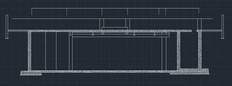
- Using the LINE, XLine command (Horizontal and vertical), draw the industrial section as shown in figure.
- Using the Hatch Command,
Pattern AR-CONC is used to fill the concrete walls.
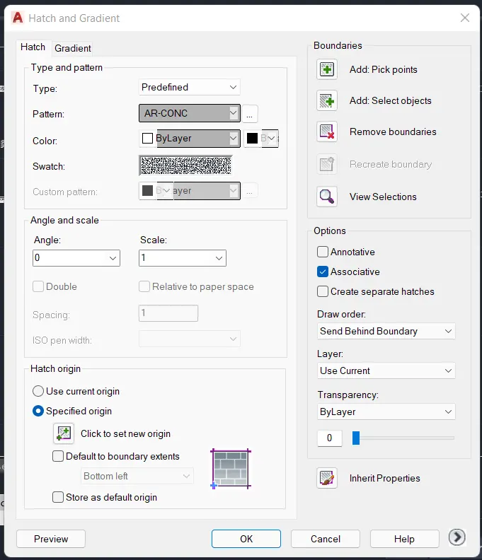
- The following image shows the walls with AR-CONC hatch pattern.
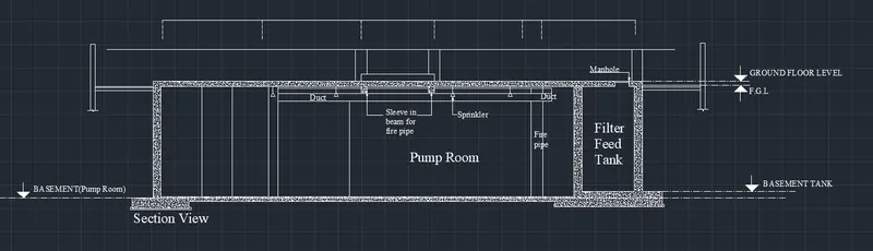
- Using Dtext command, the texts are mentioned at required places.
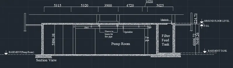
- Using DIM LIN and DIMCONTINUE command, the dimensions are mentioned.
- Using Express tools ( Enclose an object), i have used circles to enclose some objects as shown in the figure.
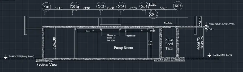
RESULT: