Creating Conceptual mass in REVIT and Creation of Sinusoidal curve and a Parametric stadium using Dynamo
Name: Allan Bryan Jayson Cruz
Course: Master’s Certification Program in High-Rise Building Design & Analysis
Date: February 27, 2022
Challenge 10_Creating Conceptual mass in REVIT and Creation of Sinusoidal curve and a Parametric stadium using Dynamo
********************************************************
1 Aim & Introduction
***************
Aim
This challenge aims to give the student an experience using the Dynamo software. This will familiarize the students on how the software can effectively be used together with the software. It also aims to highlight the specialties of the software on creating complex structures or element designs that can be used in modeling the building.
Introduction
Revit is a building information modelling software that allows the user to create and design a 3D model building structure. It is an architectural, structural, and mechanical software where the user can provide 3D illustration of the building as well as its design.
********************************************************
2 Detail Procedure
***************
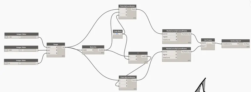
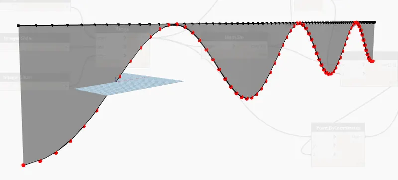
1) Using Dynamo create a set of sinusoidal points and create a curve and create a surface out of the curve.
PROCEDURE:
- Open the Dynamo software on the Manage tab of the Revit Software.

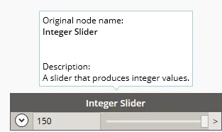
- First create an integer slider. Provide the range of the integer sliders as you desire.
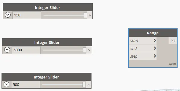
- Give the value for Start, End and Step then create a Range tab and connect the integer slider to the appropriate connection.
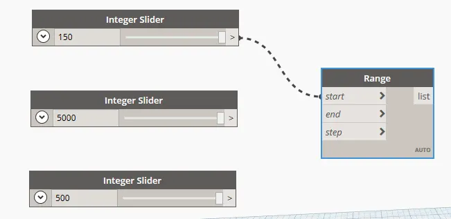
- To connect, drag the arrow to the appropriate connection.
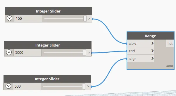
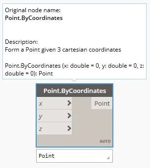
- Then create the Point.ByCoordinates tab with xyz option.
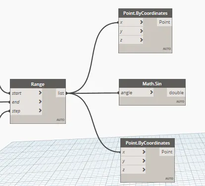
- Create another Point.ByCoordintaes tab and a Math.Sin tab for the sinusoidal curve. Connect the X coordinate to the list together with the angle.
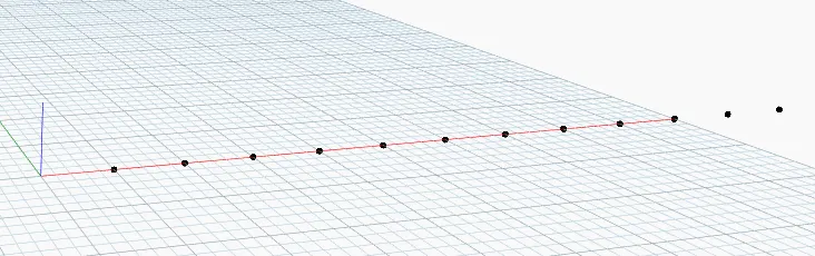
- Notice that the first set of sinusoidal points will be shown.
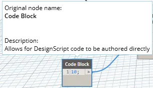
- Now create a Code Block and a Product tab for the second set of sinusoidal points.
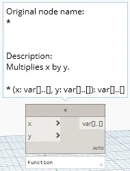
- Connect the following points together.
- Code Block --> Z coordinate of Point by Coordinates (1)
- Math.Sin --> Y coordinate of Point by Coordinates
- Math.Sin --> X of Product
- Code Block --> Y of Product
- Product Variant --> Z coordinate of Point by Coordinates (2)
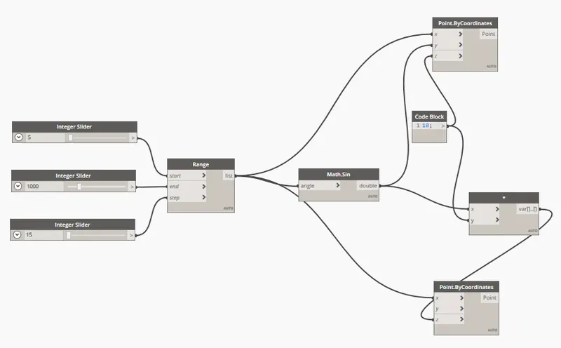
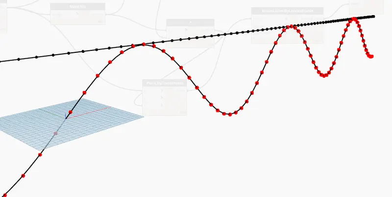
- Now you can see the sinoidal points on the dynamo window.

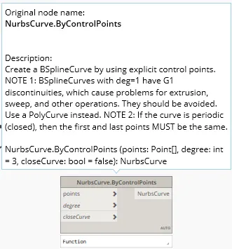
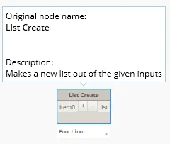
- To create the sinusoidal curve, create 2 NurbsCurve.ByControlPoints and a ListCreate tab.
- Now connect the following.
- Point.ByCoordinates (1) --> Points of NurbsCurve.ByControlPoints (1)
- Point.ByCoordinates (2) --> Points of NurbsCurve.ByControlPoints (2)
- NurbsCurve.ByControlPoints (1) --> Item 0 of List Create
- NurbsCurve.ByControlPoints (2) --> Item 1 of List Create
- Click the + sign on List Create to create a new item
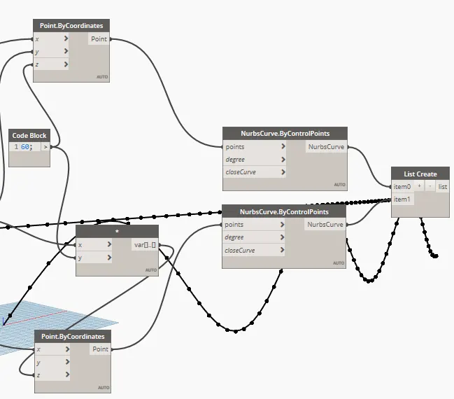
- Now the line on the curves will be shown.
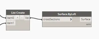
- Add the Surface.ByLoft tab to create the surface.
- Connect the List Create to the Surface.ByLoft tab.
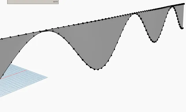
- Now the surface will be shown on the model.
COMPLETE DIAGRAM:
SINUSOIDAL CURVE MODEL:
***************
2) Create a conceptual layout of floor plan in dynamo . Using the tools available in dynamo link the lines to appropriate model elements in Revit by choosing the wall types and wall parameters. Make use of the sliders to slide through the height of the wall and length of the wall.
PROCEDURE:
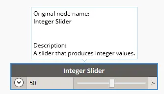
- Create the Integer Sliders on Dynamo. Create 2.
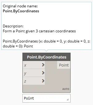
- Create the Points.ByCoordinate with X, Y, Z on Dynamo. Create 4.
- Connect the following:
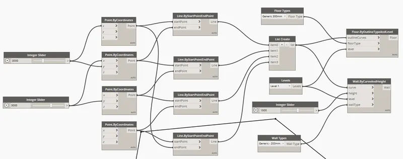
- Integer Slider (1) --> X of Point (1)
- Integer Slider (1) --> Y of Point (2)
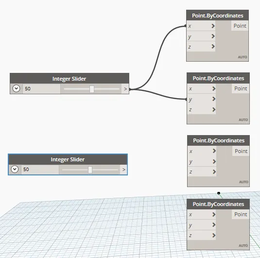
- Connect the following:
- Integer Slider (2) --> X of Point (2)
- Integer Slider (2) --> Y of Point (3)
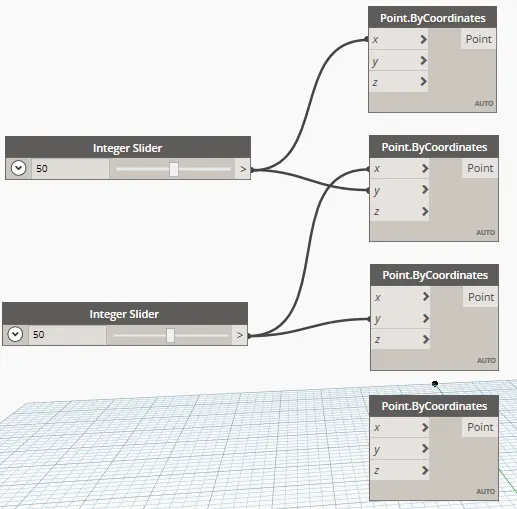
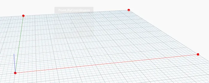
- Points will be created on the Dynamo window.
- Connect the points with line using the Line.ByStartPointEndPoint tab. Create 4.
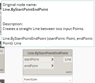
- Connect the following:
- Point (1) --> Start of Line (1)
- Point (2) --> End of Line (1)
- Point (2) --> Start of Line (2)
- Point (3) --> End of Line (2)
- Point (3) --> Start of Line (3)
- Point (4) --> End of Line (3)
- Point (4) --> Start of Line (4)
- Point (1) --> End of Line (4)
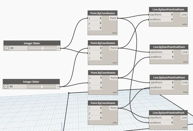
- The lines will now be created.
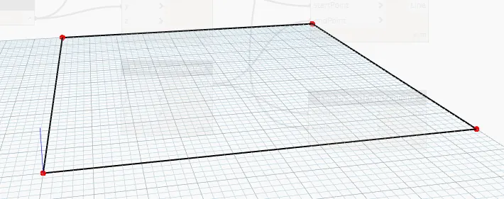
- Revit will show the following depending on the scale of your dimensions.
- Now create a List Create with 4 items.
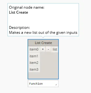
- Connect the following:
- Line 1 --> Item 0 of List Create
- Line 2 --> Item 1 of List Create
- Line 3 --> Item 2 of List Create
- Line 4 --> Item 3 of List Create
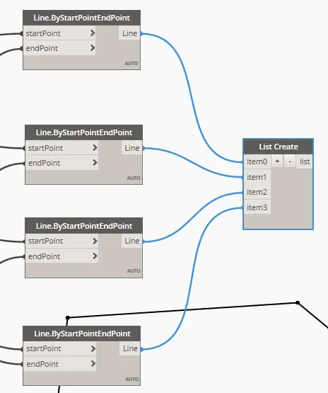
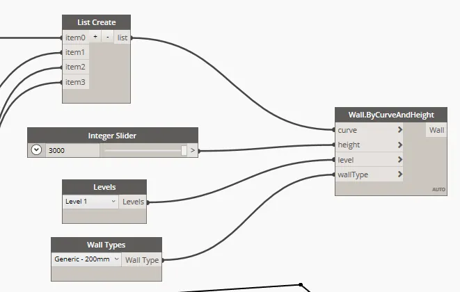
- Now add the following tabs for the wall properties.
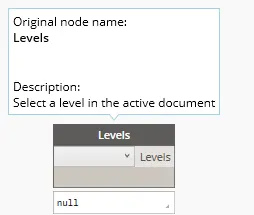
- Levels
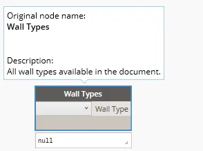
- Wall Types
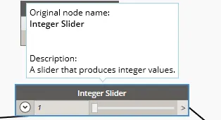
- Integer Slider - For the Height
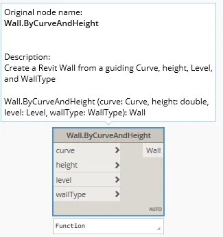
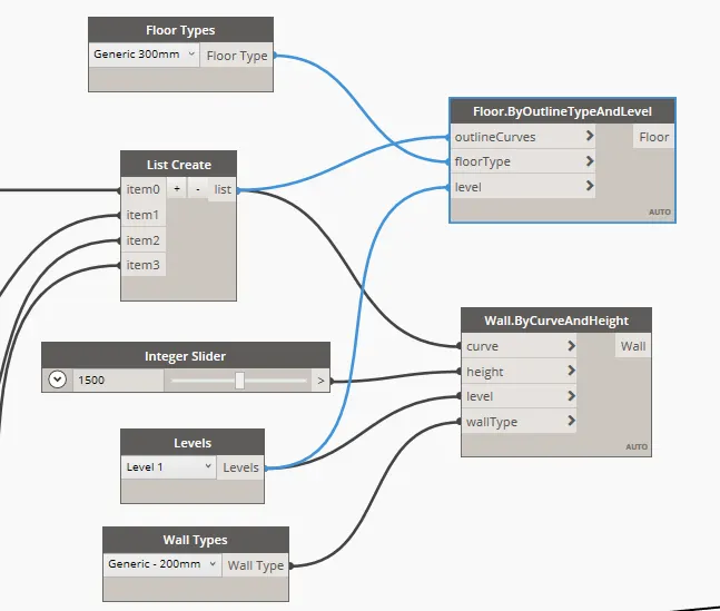
- Wall.ByCurveAndHeight
- Now connect the following:
- List Create --> Curve of Wall.ByCurveAndHeight
- Integer Slider --> Height
- Levels --> level of Wall.ByCurveAndHeight
- Wall Types --> wallType of Wall.ByCurveAndHeight
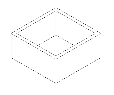
- Check the revit software to see the created wall.
- To create the floors, add the following.
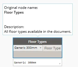
- Floor Types
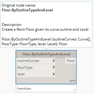
- Floor.ByOutlineTypeAndLevel
- Now connect the following:
- List Create --> outlineCurves of Floor.ByOutlineTypeAndLevel
- Floor Types --> floorType of Floor.ByOutlineTypeAndLevel
- Levels --> level of Floor.ByOutlineTypeAndLevel
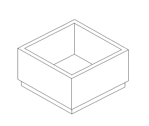
- The floor will be created together with the wall on the Revit interface.
FINAL DIAGRAM:
***************
3) Create an array of model elements in Revit. Use dynamo to vary the properties of model elements by using the slider or code block
PROCEDURE:
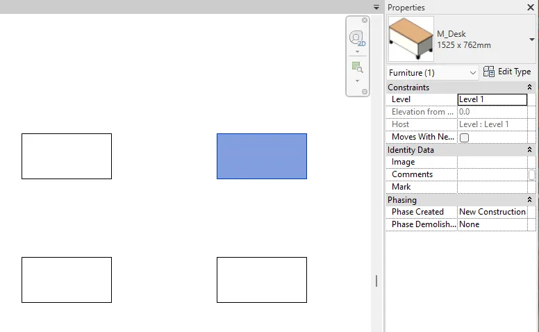
- Provide an element on the revit software.
- Now go to Dynamo and create the Select (Multiple) Model Elements tab.
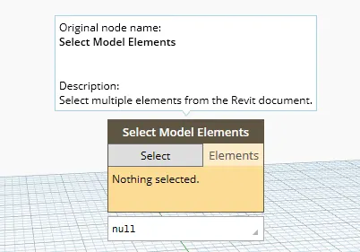
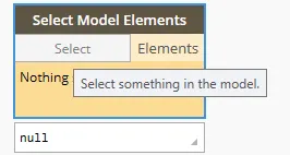
- Now select the elements on Revit by clicking the "Select" button and then going back to revit and selecting the desired elements.
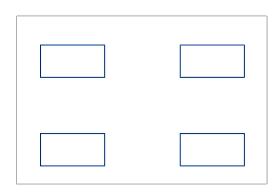
- The selected elements will be reflected on the Select Model Elements tab.
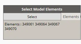
- Now create the following:
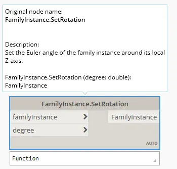
- FamilyInstance.SetRotation
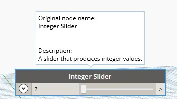
- IntegerSlider
- Now connect the following:
- Elements --> familyInstance
- Integer Slider --> degree
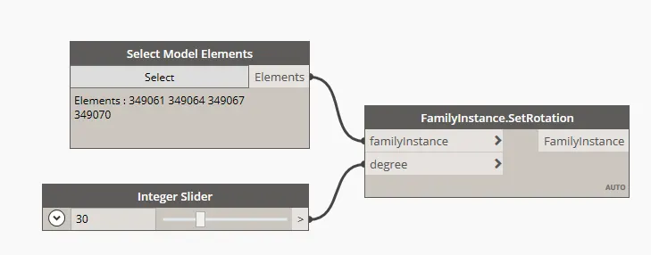
- Check the revit model. The element will be rotated.
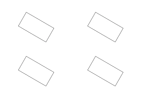
- You can control the rotation of the elements using the slider.
***************
4) Create a conceptual mass in Revit and develop a parametric column by dividing the surfaces and apply the concepts similar to used in parametric walkway modelling. Use triangular bent or square shaped panels to add finish to the parametric column
PROCEDURE:
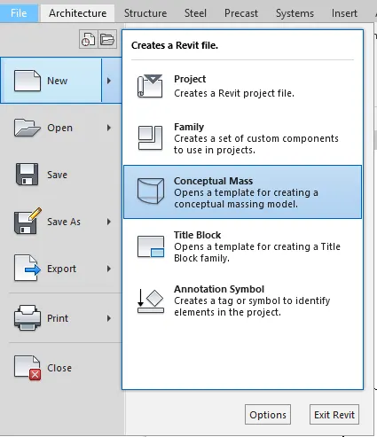
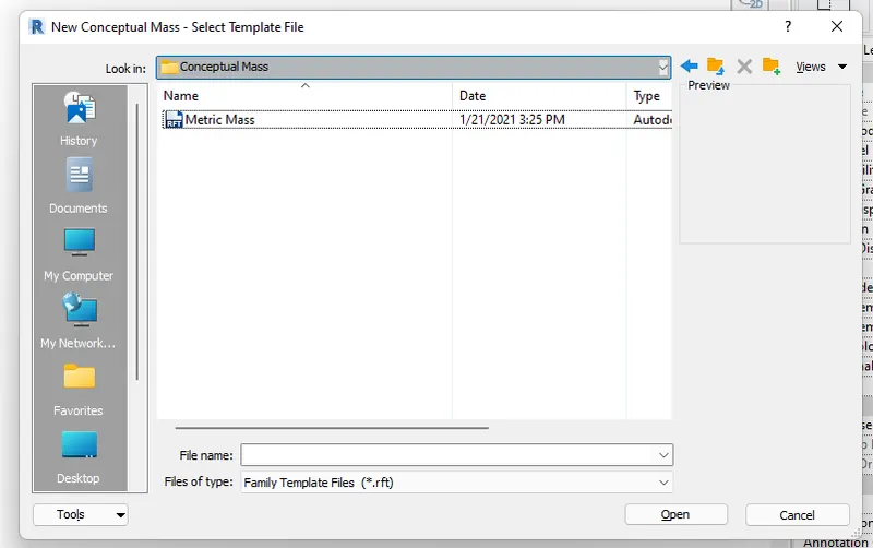
- Create a new revitmodel using the conceptual mass template.
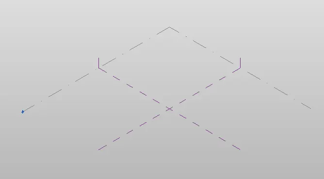
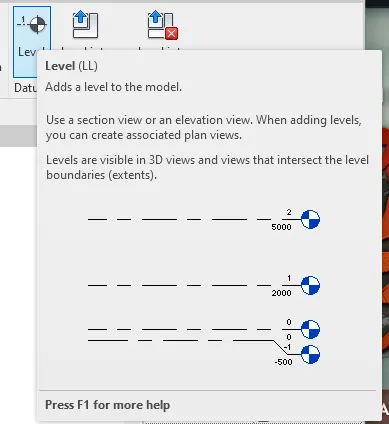
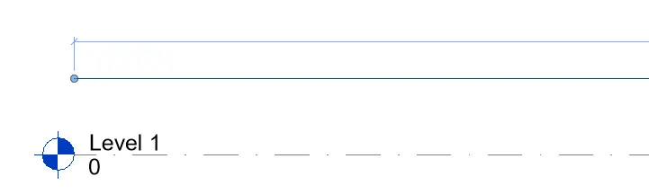
- First create a new level with desired offset using the Level tool. Set the elevation to 3000.
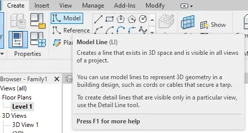
- Now go the plan and create the path. Use the model line tool.
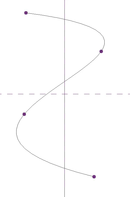
- Once the path is finished, you can go to the 3D view and set the Plane parameters. Use the Set tool under modify tab.
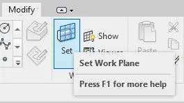
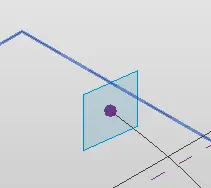
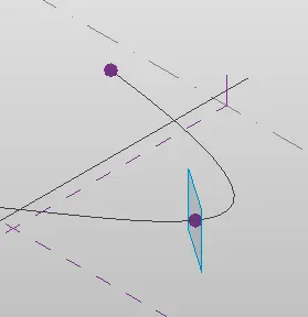
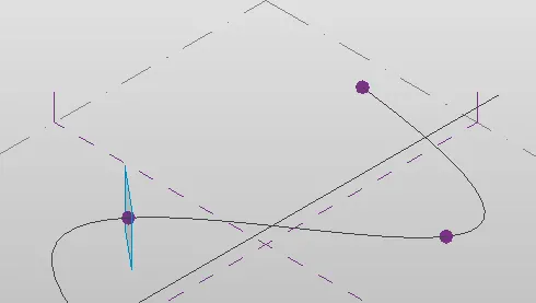
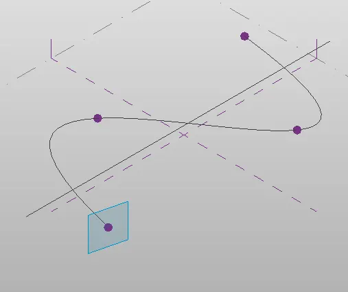
- Set the plane on all points of the path.
- Once the planes are set, draw a circumscribed polygon on each point with the Level height created earlier. H=3000.
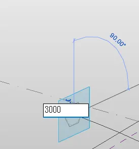
- Follow the image above on all points.
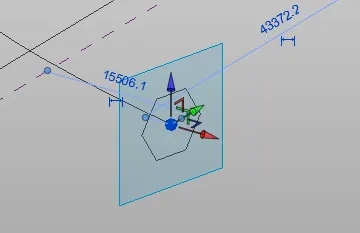
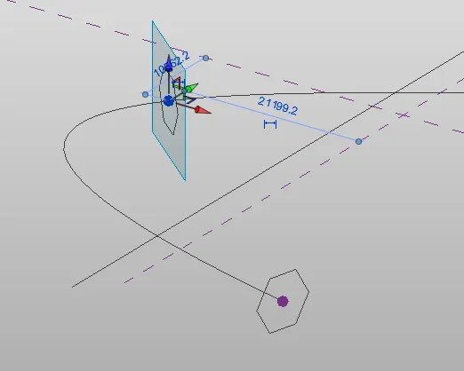
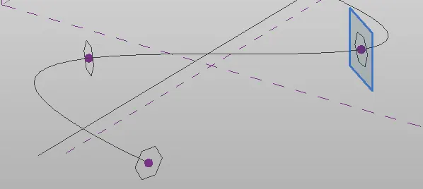
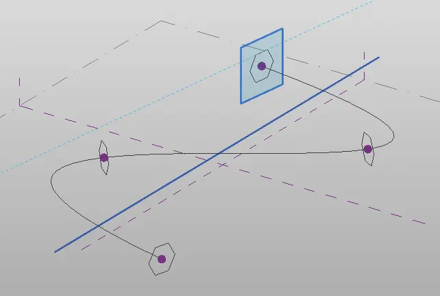
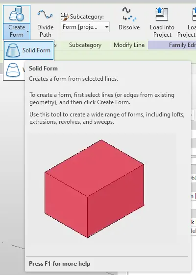
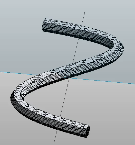
- Now create the form of the the path using the created shape. Select the spline together with the first created shape. After selecting, choose the Create Form-->Solid Form tool.
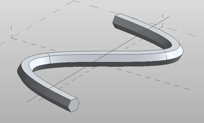
- The model will look like this.
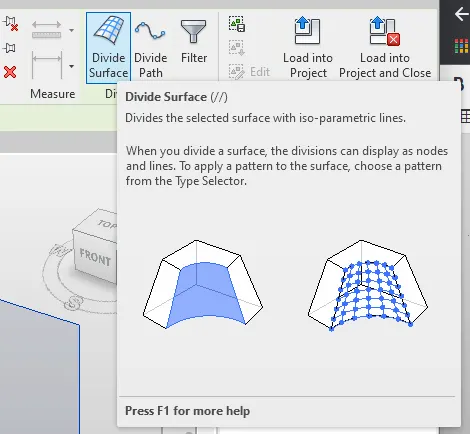
- Now divide surface using the Divide Surface tool.
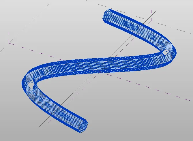
- Then apply the triangle bent as a pattern under the properties tab.
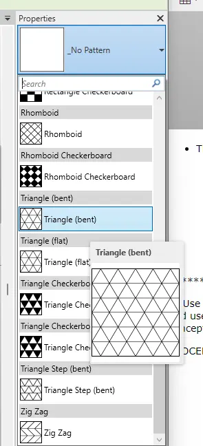
- Notice that the solid model will change accordingly.
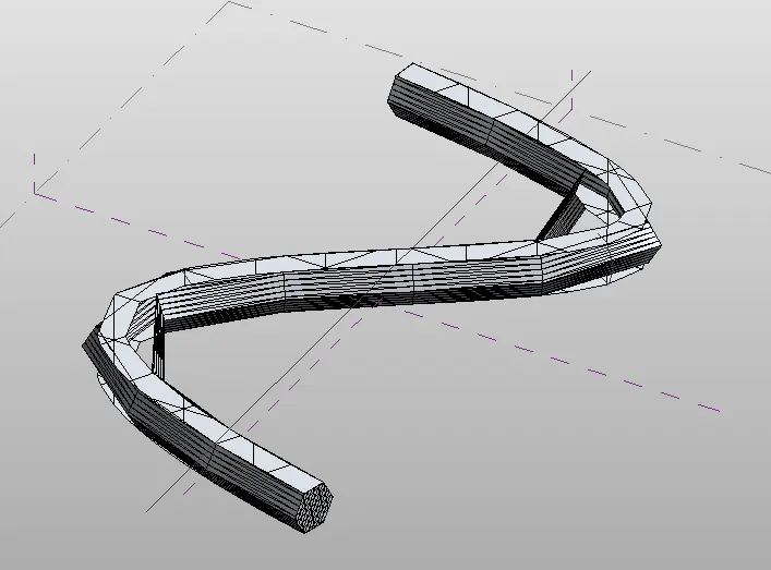
- You can adjust the Grid numbers of the pattern to create even smoothness of the solid element.
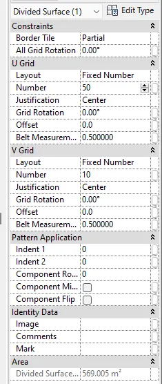
- Once the grids are decided, the model will look smoother like the one below.
***************
5) Use Dynamo to work on developing a Parametric Stadium. List your parameters and use the visual programming approach to complete the modelling, You can use the concepts discussed in parametric high rise tower in class for reference.
PROCEDURE:
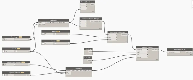
- On the Dynamo interface create the following.
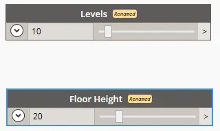
- Integer Slider - Rename for floor levels
- Integer Slider - Rename for floor heights
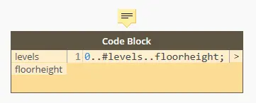
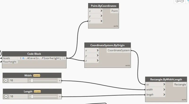
- Now add a code block with the following formula.
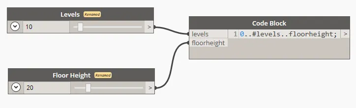
- Now describe the elements by connecting the integer slider to the code block.
- Now Add integer sliders with the following properties.
- Width
- Length
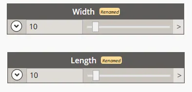
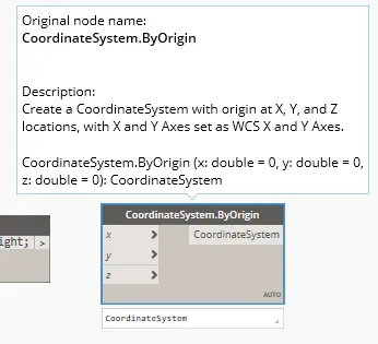
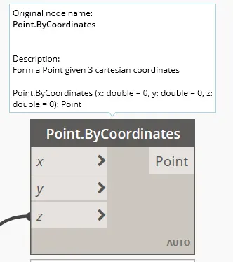
- Then, add a CoordinateSystem.ByOrigin and Points.ByCoordinates with the X, Y, Z coordinates.
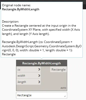
- Also, add a Rectangle.ByWidthLength using coordinates.
- Now connect the following.
- Code Block --> Z of Point
- Code Block --> Z of CoordinateSystem
- CoordinateSystem --> cs of Rectangle
- Slider Width --> width of Rectangle
- Slider Length --> length of rectangle
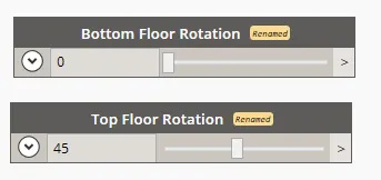
- Now Add integer sliders with the following properties.
- Bottom Floor Rotation
- Top Floor Rotation
- Then add another code block with the following formula.
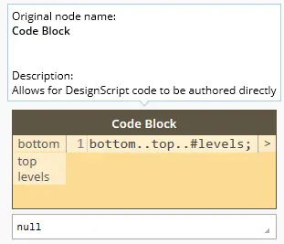
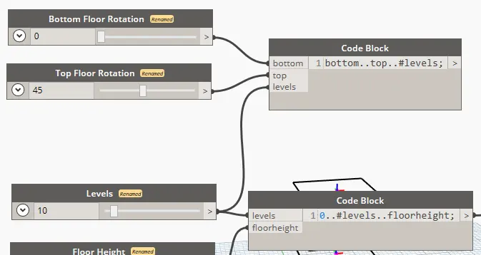
- Connect the following:
- Slider Bottom --> bottom Code Block
- Slider Top --> top Code Block
- Slider Levels --> levels Code Block
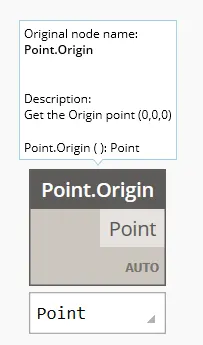
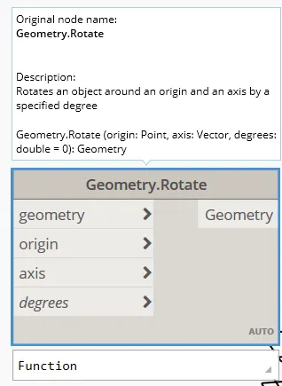
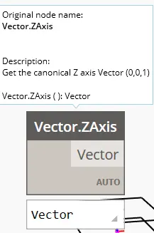
- Now create a Point.Origin, Geometry Rotate, and a Vector.ZAxis.
- Connect the following:
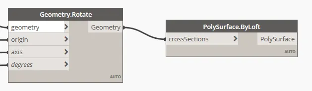
- Rectangle --> geometry of Geometry.Rotate
- Point.Origin --> origin of Geometry.Rotate
- Vector.ZAxis --> axis of Geometry.Rotate
- Code Block (2 - bottom, top, levels) --> degrees of Geometry.Rotate
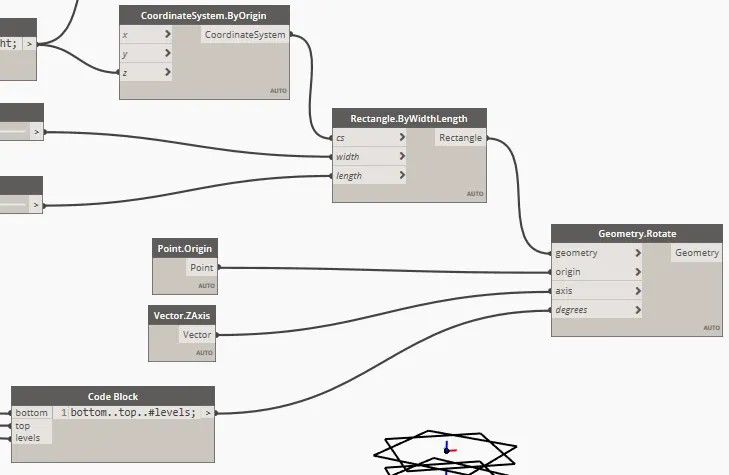
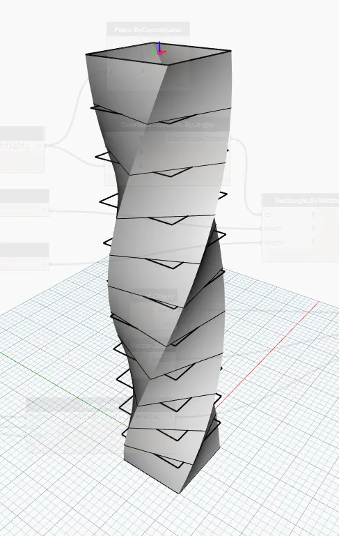
- The base geometry is complete. Create the surface using the PolySurface.ByLoft tool.
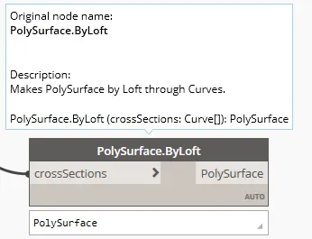
- Connect the Geometry.Rotate to the PolySurface.
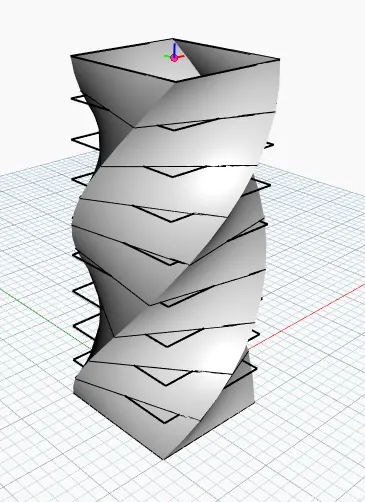
- The model will look like the one below.
FINAL DIAGRAM:
FINAL MODEL:
********************************************************
3 Conclusion
***************
The Revit software together with the Dynamo software can provide a more advanced modeling of building structures. Aside from the real time edit provided by the software, using the Dynamo software creates the illusion of a real life image of the building structure. Limitations on the modeling of a building will be lessen only the creativity of the modeler.