Creating Conceptual mass in REVIT and Creation of Sinusoidal curve and a Parametric stadium using Dynamo
Creating Conceptual mass in REVIT and Creation of Sinusoidal curve and a Parametric stadium using Dynamo
1) Using Dynamo create a set of sinusoidal points and create a curve and create a surface out of the curve.
Aim: To create a set of Sinusoidal points,a curve and a surface out of the curve using Dynamo.
Introduction: The Procedure to create Sinusoidal points, a curve and a surface from the curve using Dynamo is explained in detail and the final result is given.
Procedure:
- In the new project dialog box, Select Architectural Template from the drop-down list.
- Create new>project>Ok.
- Go to Manage Dynamo.
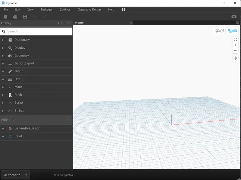
- In the Dynamo homepage>New.
- The Dynamo workspace Opens up.
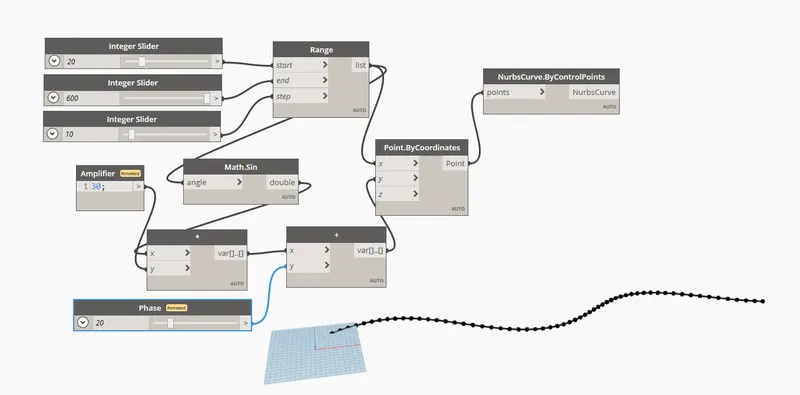
- Search Integer Slider.
- Add 3 Integer Sliders.
- Change the min., max. and Step values of the integer Slider.
- Search and add Range.
- Assign Suitable values to the integer slider and connect them to the the Range( Start,End and Step respectively).
- Search and add point.ByCoordinates.
- Connect the range value to the x Coordinate.
- Search and add Math.Sin node and connect it to the range node.
- Search and insert a Code Block , Rename it as Amplifier and insert value as 30.
- Search and insert code product node, and connect the math.sin and amplifier values to it.
- Search and add integer slider and rename it as phase for the sinusoidal curve.
- Search and insert Add node and connect the product output and phase output to it.
- Next connect the output from the add '+' node to the y-Coordinate.
- Search and add Nurbscurve.ByControlpoints and Connect the output from the point.Bycoordinates node to it.
- A Sinusoidal curve will be created as Shown in the figure below.
- Select all the processing and output nodes.
- Go to edit>create custom node.
- Enter the name,Description and category>Ok.
- The input, processing and output nodes will be grouped as follows.
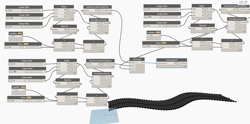
- Select the previously grouped nodes,Copy and paste them twice.
- Change the phase value of the curves to view them.
- Three Sinusoidal curves will be created as shown below.
- Search and insert List create.
- Connect the three curve nodes to the list as items.
- Search and insert surface.ByLoft.
- Connect the list output to the crosssection in surface.ByLoft node.
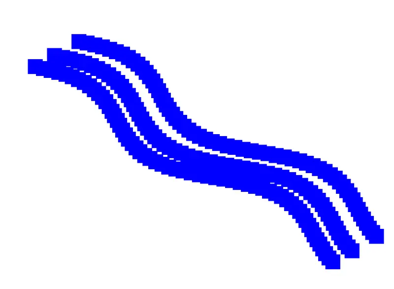
- A surface will be created from the curves.
Result:
It has been illustrted in detail how to create a set of Sinusoidal points, a set of curves and a surface out of the curves in Dynamo.
-------------------------------------------------------------------------------------------------------------------------------------------
2) Create a conceptual layout of floor plan in dynamo . Using the tools available in dynamo link the lines to appropriate model elements in Revit by choosing the wall types and wall parameters. Make use of the sliders to slide through the height of the wall and length of the wall.
Aim: To create a Conceptual layout of floor plan in Dynamo.
Introduction: The Procedure to create a Conceptual layout of floor plan in Dynamo and assign the appropriate model elements to the wall is explained in detail and the final result is given.
Procedure:
- In the new project dialog box, Select Architectural Template from the drop-down list.
- Create new>project>Ok.
- Go to Manage Dynamo.
- In the Dynamo homepage>New.
- The Dynamo workspace Opens up.
- Search Integer Slider.
- Add 2 Integer Sliders.
- Change the min., max. and Step values of the integer Slider.
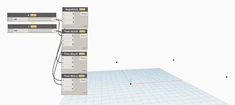
- Search and add point.bycoordinates X 4 times (four points to create the layout).
- Rename the node as Shown below.
- Connect the integer slider to the point coordinate nodes so as to generate 4 points.
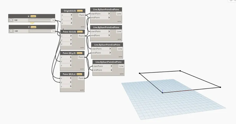
- Search and insert line.bystartpointendpoint X 4 times.
- Connect them to the point by coordinates nodes.
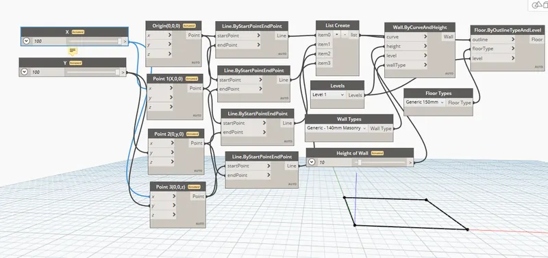
- Search and insert List.Create.
- Connect the lines to the list items.
- Search and insert levels.
- Select Level 1.
- Search and insert wall types.
- Select Generic 8".
- Search and insert number slider.
- rename it as Height of wall.
- Search and insert wall.bycurveandheight.
- Connect all the above parameters to this node to generate the wall.
- Search and iinsert floor types.
- Select the Suitable Floor type.
- Search and insert Floor.Byoutlinetypeandlevel.
- Connect the List, Level and floor type parameters to this node.
Result:
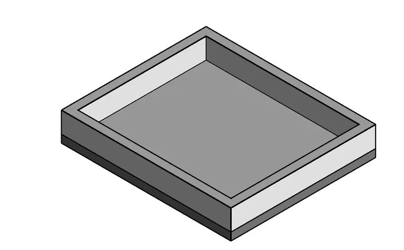
It has been illustrted in detail how to create a Conceptual floor layout,and assign height and material to the model elements in Dynamo.
-------------------------------------------------------------------------------------------------------------------------------------------
3) Create an array of model elements in Revit. Use dynamo to vary the properties of model elements by using the slider or code block.
Aim: To create an array of model elements in Revit and Change/adjust their properties using Dynamo.
Introduction: The Procedure to create an Array of model elements in Revit and to vary their properties/alignment using dynamo is explained in detail and the final result is given.
Procedure:
- In the new project dialog box, Select Architectural Template from the drop-down list.
- Create new>project>Ok.
- Go to architecture>Architecture Columns.
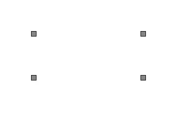
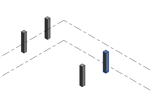
- Create 4 Columns.
- Go to Default 3D View.
- Go to Manage Dynamo.
- In the Dynamo homepage>New.
- The Dynamo workspace Opens up.
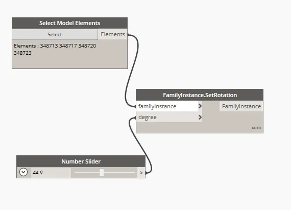
- Search and insert Select model elements(Multiple).
- Click Select go to Revit workspace and Select all the created columns.
- Search and insert number slider.
- Enter min.30, Max.90 and Step 1.
- Search and insert set rotation.
- Connect the model elements and number slider to the Set rotation node.
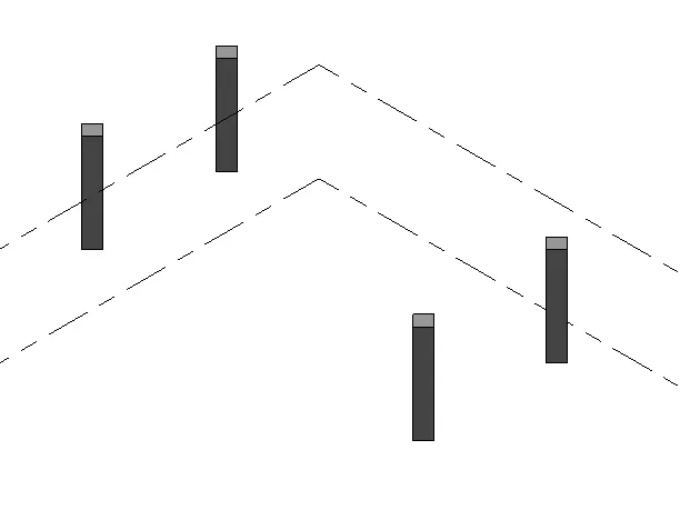
- Slide the number slider to rotate the columns.
Result:
It has been illustrted in detail how to create an array of model elements in Revit and to vary their properties/alignment using Dynamo.
-------------------------------------------------------------------------------------------------------------------------------------------
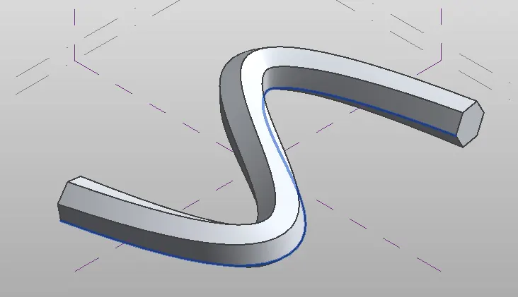
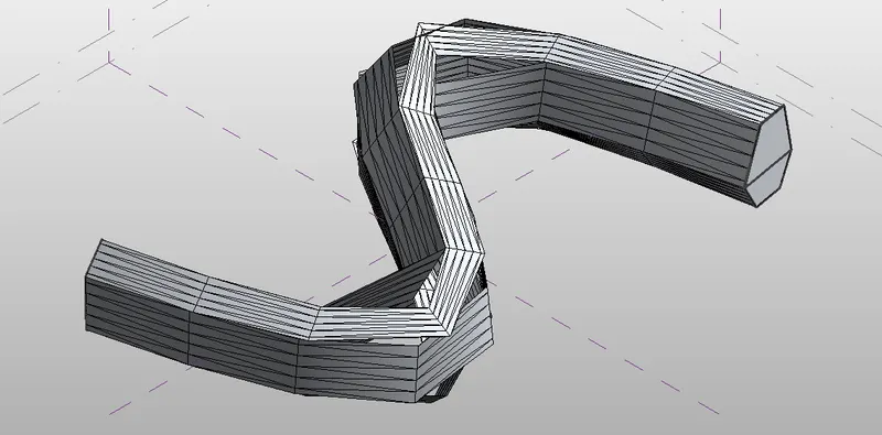
4) Create a conceptual mass in Revit and develop a parametric column by dividing the surfaces and apply the concepts similar to used in parametric walkway modelling. Use triangular bent or square shaped panels to add finish to the parametric column.
Aim: To create a conceptual mass in Revit, and develop a parametric column by dividing the surface and add finish to the column using triangular bent panels.
Introduction: The Procedure to create a Conceptual mass in revit, and develop a parametric column by dividing the surface and add finish to the column using triangular bent panels is explained in detail and the final result is given.
Procedure:
- In the Revit home page Click on new under the families option.
- Select Conceptual mass> metric mass>Open.
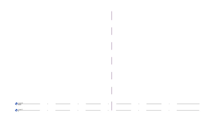
- Go to Create>Level.
- Addd Level 2 at a height of 4000mm from Level 1.
- Project browser>Floor Plan>Level 1.
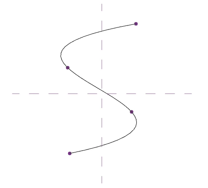
- Go to Create>Model>spline.
- Draw a S-Shape.
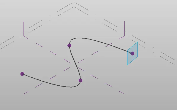
- Go to 3D View.
- Select the end control point of the Spline.
- Set work plane.
- Show Work plane.
- Similarly, Set the work plane at all control points.
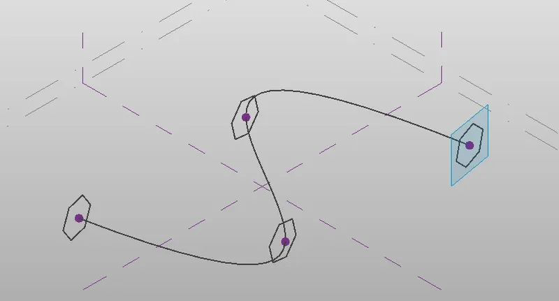
- Select Circumscribed polygon tool.
- Sides:6.
- Size 4000mm.
- Draw a polygon at each of the control points of the spline.
- Select all the Circumscribed polygons created at each point, and the spline.
- Click on Create Form> Solid Form.
- Select the Entire Created model.
- Filter select only Form.
- Click apply>Ok.
- Again Select the entire model>Filter>Select only the divided surface and Click Apply.
- Go to properties pattern.
- Select the triangle( bent) pattern.
- Adjust the number of U and V grids as required.
Result:
It has been illustrted in detail how to create a Conceptual mass in Revit and how to add finish to the parametric model using triangular bent panels.
-------------------------------------------------------------------------------------------------------------------------------------------
5) Use Dynamo to work on developing a Parametric Stadium. List your parameters and use the visual programming approach to complete the modelling, You can use the concepts discussed in parametric high rise tower in class for reference.
Aim: To Develop prametric Stadium using Dynamo.
Introduction: The Procedure to develop a parametric stadium using Dynamo is explained in detail and the final result is given.
Procedure:
- In the new project dialog box, Select Architectural Template from the drop-down list.
- Create new>project>Ok.
- Go to Manage Dynamo.
- In the Dynamo homepage>New.
- The Dynamo workspace Opens up.
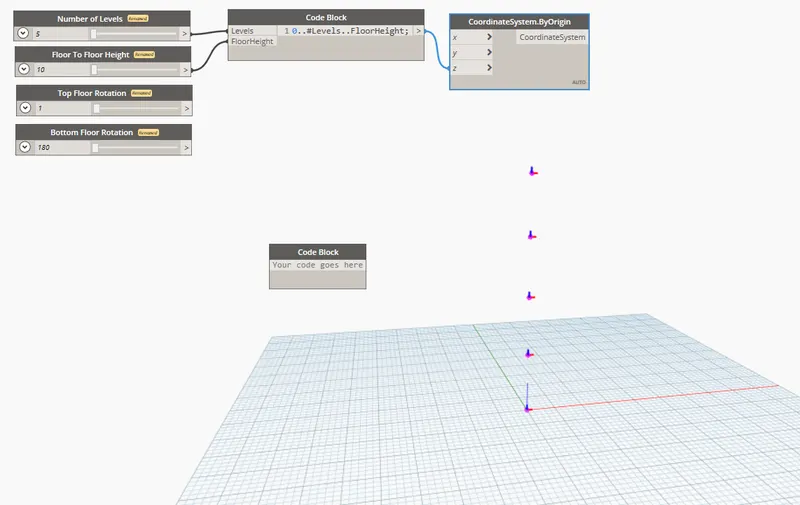
- Search and add 4 Integer Slider.
- Rename the integer sliders.
- Search and add 4 Code Block.
- Create code as 0..#Levels..Floor Height.
- Connect the no. of levels and floor height sliders to the above created code block.
- Search and insert Coordinatesystem.Byorigin.
- The output from the code block to Z axis in the Coordinatesystem.By origin node.
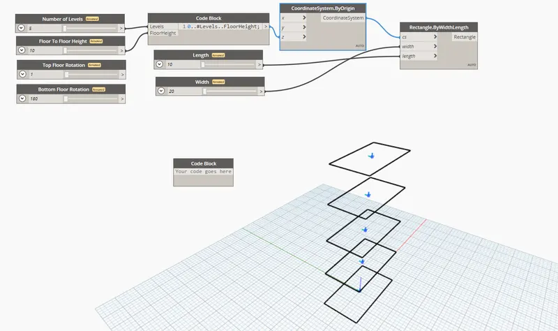
- Search and insert Rectangle.Bywidthlength.
- Search and insert 2Xintegersliders.
- Rename them as width and length.
- Connect the integer sliders and Coordinates by origin nodes to the rectangle node.
- Search and insert Geometry.Rotate.
- Search and insert point.origin.
- Search and insert Vector.Zaxis.
- Search and insert CodeBlocks.
- Enter code as bottom..Top..#Levels.
- Conncet the outputs from rectangle,point.Origin,Vector.Zaxis and the above codeblock to the geometry node.
- Search and insert polysurface.ByLoft.
- Connect the output from the geometry.rotate to the polysurface.ByLoft node.
- The parametric 3D model is ready.
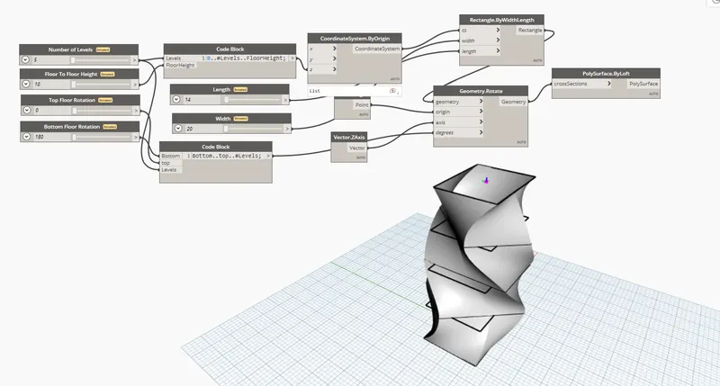
Result:
It has been illustrted in detail how to develop a parametric stadium using dynamo.All the parameters used for the modelling have been listed clearly.