Creating Conceptual mass in REVIT and Creation of Sinusoidal curve and a Parametric stadium using Dynamo
1) Using Dynamo create a set of sinusoidal points and create a curve and create a surface out of the curve.
AIM : TO DRAW THE CURVE BY USING A SET OF SINUSOIDAL POINTS AND CREATE A SURFACE TO IT
TOOLS USED
ARCHITECTURAL TEMPLATE
MANAGE TAB
DYNAMO
PROCEDURE :
STEP 1 : TO OPEN REVIT NEW FILE
SETP 2 : TO OPEN THE DYNAMO OPTION
STEP 3 :
Go to search box in dynamo file and search point by co-ordinates and range by co-ordinates.
Now search code blocks in the search box and load atleast three code blocks.
Rename the code blocks as start, end and type.
Give them the input values as 10,200 and 1 to start , end and type respectively.
Now join those 3 code blocks to 3 respective coponents of range.
Now load another code clock and prepare 3 components(start , end,type) in it.
Now join those 3 coponentsto the new code block.
Load another code block and rename it as number of values and assign the value as 10.
Now Add a code block and assign 3 coponents(start, end and number).
Now load sine factor and a code block.
Rename that code block asamplifier and fix the value of thatas 20.
Load the product factor and assign x,y coponents to that product.
Now join sine and amplifier to product.
Add integer slider and set the minimum, maximum and step value as 20, 50 and 1respectively.
Load add factor and join those values to integer slider.
Now add surface to the curve.
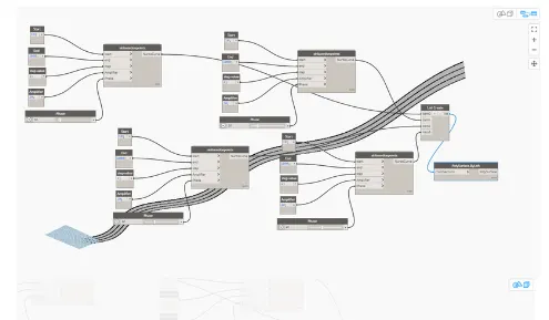
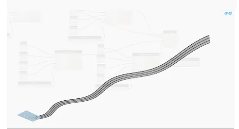
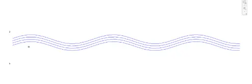
RESULT :
TO CREATED THE CURVE BY USING A SET OF SINUSOIDAL POINTS AND CREATED A SURFACE TO IT
2) Create a conceptual layout of floor plan in dynamo . Using the tools available in dynamo link the lines to appropriate model elements in Revit by choosing the wall types and wall parameters. Make use of the sliders to slide through the height of the wall and length of the wall.
AIM : TO CREATE A CONCEPTUAL LAYOUT OF FLOOR PLAN IN DYNAMO
TOOLS USED
ARCHITECTURAL TEMPLATE
MANAGE TAB
DYNAMO
PROCEDURE :
STEP 1 : TO OPEN REVIT NEW FILE
SETP 2 : TO OPEN THE DYNAMO OPTION
STEP 3 :
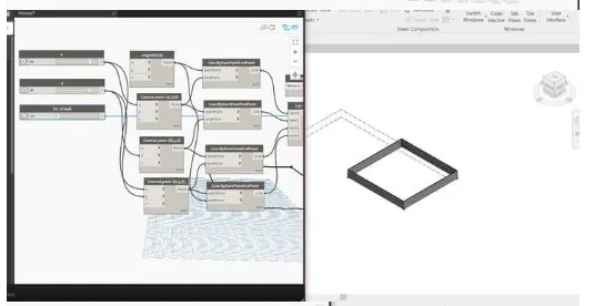
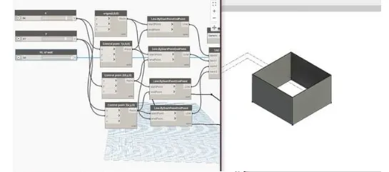
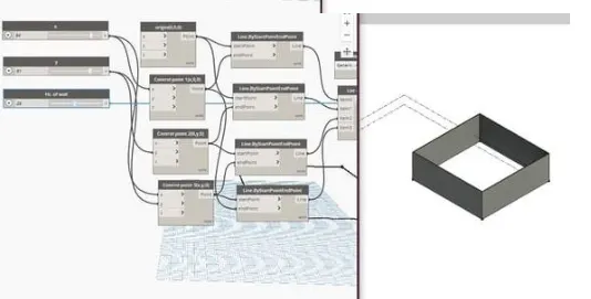
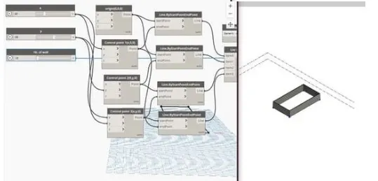
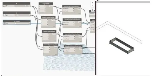
In the library type points and select 4 times points by coordinate and rename it as(origin.controlpointl.controlpoint 2.controlpoint
3)
Use Type slider and insert 2 and rename it to x and y.
Select the x and connect to x in controlpoint 1and controlpoint 3.
select the y and connect y incontrolpoint 2 and controlpoint 3.
Type Line and select by start end point and insert 4 times and arrange them.
connect the origin point to start pointof 1st and 2nd.
connect the control point 1 to end point of 1st and 4th.
connect the control point 2 to end point of 2nd and start point of 3rd.
connect the control point 3 to end point of 3rd and start point of 4th.
Type list and create list and i.vith the down arrow make it as 4 and connect allthe lines to item 0 to item 3.
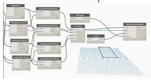
Type wall type by curve and select that.
Type wall type and insert. Type level and insert.
Typer slider and insert and rename it to height of wall.
Connect the list to curve (wall by curve).
connect wall type to wall type in (wall by curve and height).
connect level to level in wall by curve and height.
Connect the slider ht of wall to ht in wall by curve and height.
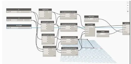
RESULT :
A CONCEPTUAL LAYOUT WAS CREATED AND DIMENSIONS SLIDED IN DYNAMO SUCCESSFULLY
3) Create an array of model elements in Revit. Use dynamo to vary the properties of model elements by using the slider or code block
AIM : TO CREATE ARRAY OF MODEL ELEMENTS IN REVIT AND VARY THE PROPERTIES OF MODEL ELEMENTS BY USING SLIDERS OR CODE BLOCK
PROCEDURE :
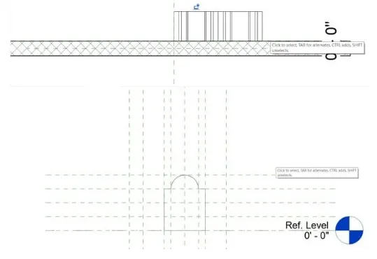
Open anew family in revit and selectgeneric model.
Create a reference planeand inoffset type 6 (Front view}.
Create extrusion and select curve and drai,v and then select line and drai.v till the mid. Select all the elementsand select mirror command.
AILign reference plane.
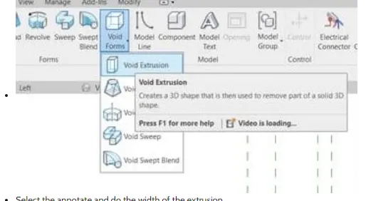
Create void forms usingextrusion i.vith offset 2
Select the annotate and do the width of the extrusion.
Save it as wall shape I.
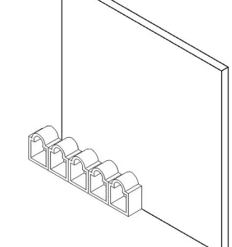
Open file > new family select generic model wall based. Select ref viei.v and select insert load into the project. Select the array and create ref plane 8.
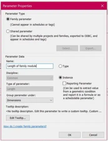
select the label>instance rename it as length of module.
In quantity type the formula Length of wall Length of module.
Save it as wall shape family.
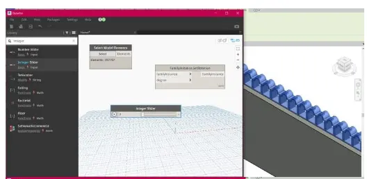
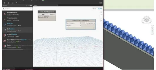
Open the manage and select dynamo. Type select elements.
Type Rotation and insert it.
Type integer slider and insert it.
Select the model elementsand select in the revit.
join the elemets to family instances.
join number slider to degree.
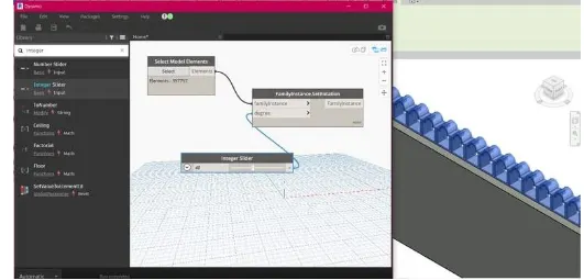
RESULT :
4) Create a conceptual mass in Revit and develop a parametric column by dividing the surfaces and apply the concepts similar to used in parametric walkway modelling. Use triangular bent or square shaped panels to add finish to the parametric column
AIM : TO CREATE A CONCEPTUAL MASS IN REVIT AND DEVELOP A PARAMETRIC COLUMN
PROCEDURE :
STEP 1 : OPEN CONCEPTUAL MASS
STEP 2 : DRAW THE SHAPE
STEP 3 : SETTINGS PLANE AND SHAPE
Open anew family inrevit and select conceptualmass
Create a levelof 10' from the base levelin the elevation viei.v and rename it
Select the floor plan view and set the workplane select the spline through pointsand draw thewalkway
select the controlpoint and set the reference and select show
select the polygon and change the sides to 4 and draw 10 rectangle in the plane in horizontaldirection Select all the control pointsand set the plane and draw the rectangle
Select the plane of all the control points and select the line and click on foam select thecomponents and select the filter and select
foam and select divide surface
select the patternas triangle bent increase the number in the grids for smooth surface
dick on the new select family and select certain panel pattern based wall select the trinagle bent pattern
select the pont element and draw the point at the midpoint create a plane and select circle of 2" and draw at the midpoint Select the circle and the triangle bent and dick foam
dick on Load it into the project
select the face and change the patern to triangle bent under family 2 (as saved) and apply it on all the surface
Walkway is made in the revit with all the properties
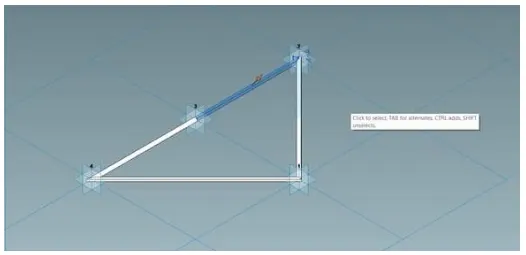
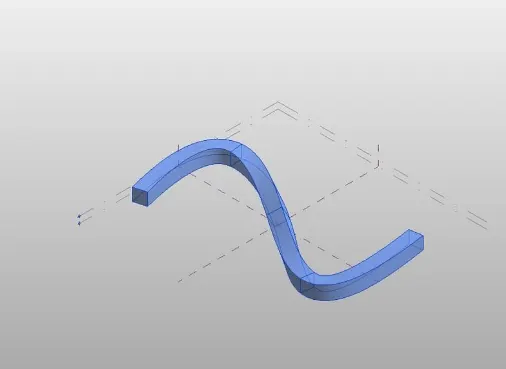
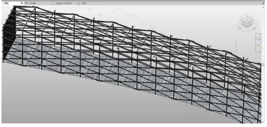
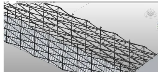
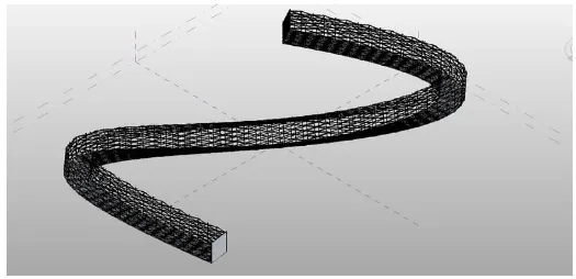
RESULT :
5) Use Dynamo to work on developing a Parametric Stadium. List your parameters and use the visual programming approach to complete the modelling, You can use the concepts discussed in parametric high rise tower in class for reference.
AIM : TO USE DYNAMO TO WORK ON DEVELOPING A PARAMETRIC STADIUM
PROCEDURE :
STEP 1 : OPENING NEW PROJECT
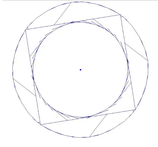
STEP 2 : CREATE POINTS AND CIRCLE
STEP 3 : CREATE SET OF CIRCLE AT DIFFERENT LEVELS
STEP 4 : CREATE SURFACE
After selecting dynamo
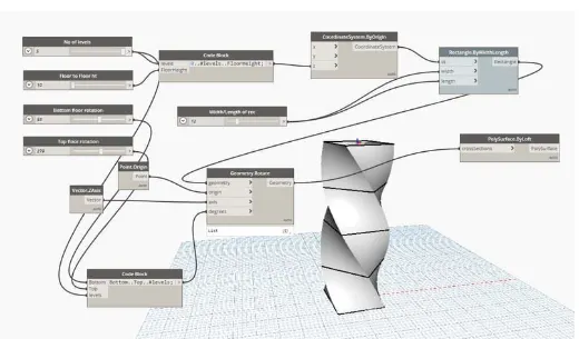
In thedynamo screen type slider and insert 4 sliderand rename it
Type points and select points by coordinate to create floor Type code block (0.#levels. Floorheight)
join levels and floor height
Type coordinate system by origin and join the code block to it in z Type code block (bottom top #levels)
jointhe bottom rotation top rotation and no of floor respectively
Type rectangle by width
Type slider and rename it as width/length of rec
join the coordinate to cs
and slider to width and length
Type rotate and insert geometry rotate
Type origin and inset point origin
Type z axis and insert
join rectangle to geometry point to origin and degrees to code book [bottom.top. #levels)
Type poly surface by loft and insert
joingeometry tocross section
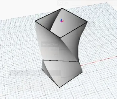
RESULT :