Creating Conceptual mass in REVIT and Creation of Sinusoidal curve and a Parametric stadium using Dynamo
INTRODUCTION :
Dynamo is an open source visual programming language for Revit, written by designers and construction professionals.
Its a programming language that allows you to type lines of code; while also creating an algorithm That consist of nodes.
Using dynamo work can be carried out with enhanced BIM capabiilities in Revit.
Dynamo and Revit an together be utilized to model and analyze complex geometries, automate repetative processes,minimize human error and export data to exer and other file types.
Dynamo can make the design process more efficient with an intuitive interface and many pre made scripting libraries availabe as well.
1. AIM :
Create sinusoidal points and curve, and create a surface out of curve using Dynamo in revit
Procedure :
Initially, open the architecture template of Revit software
Go to manage tab
In manage tab select dynamo
Then dynamo window opens
Click on new option
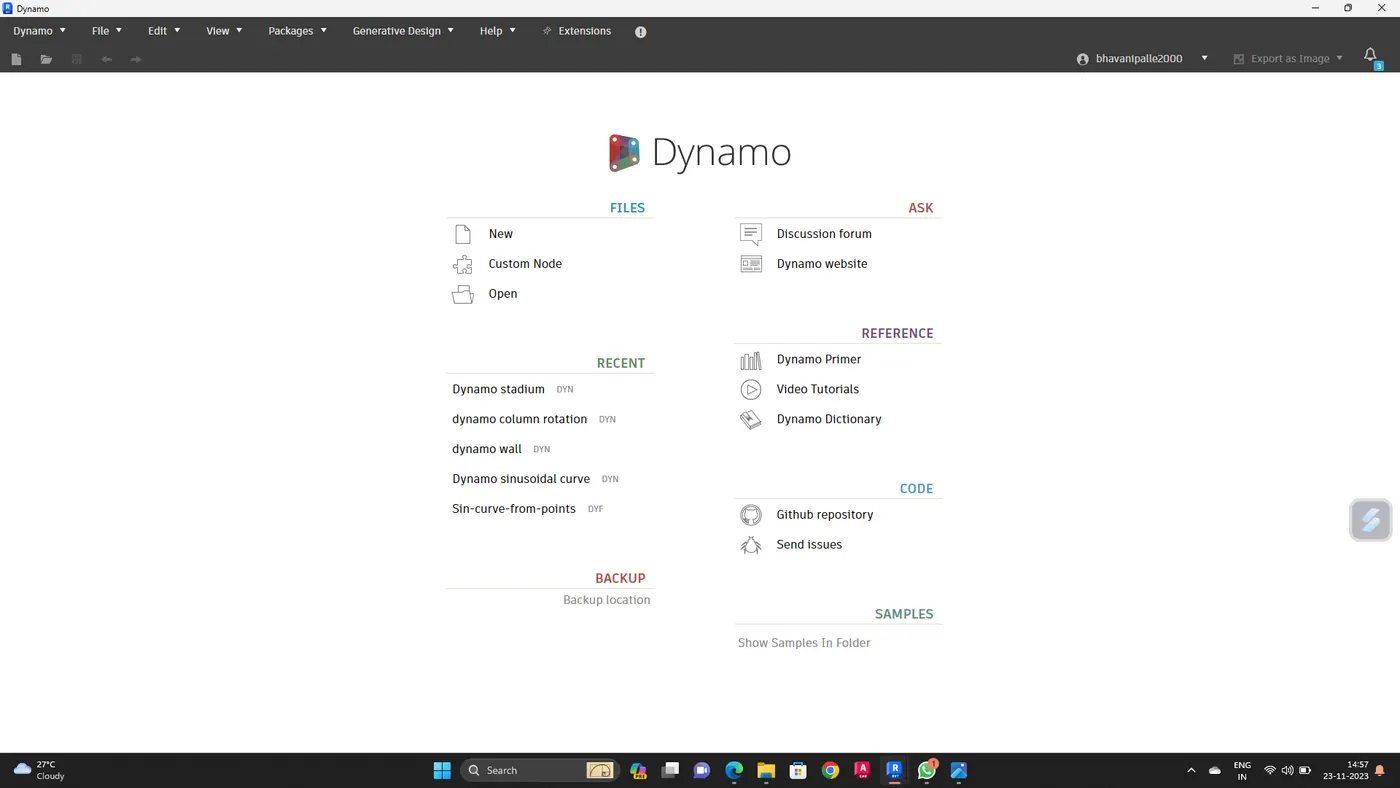
Start the process
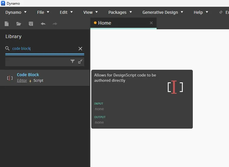
Type code block in the library searching pannel
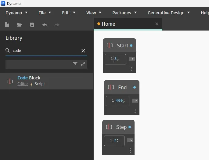
One block is named as Start
Second block is named as end
Third one is Step and give the values
Now type range and insert it
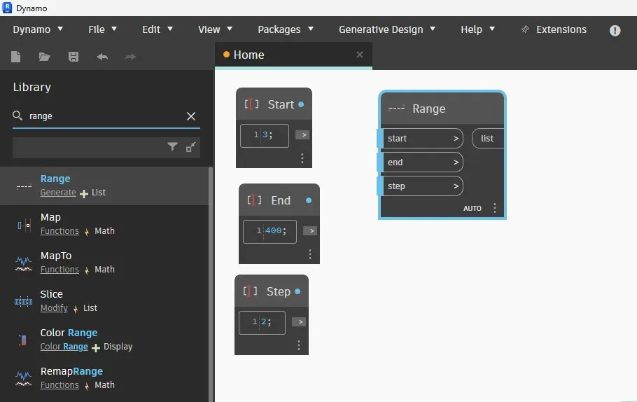
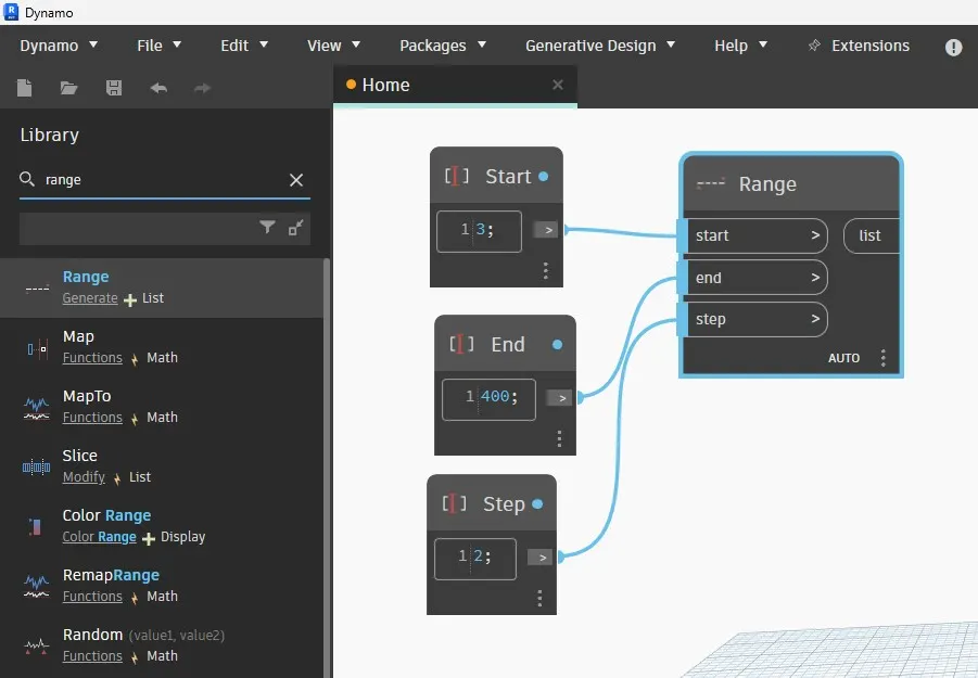
Now connect these three code block as input to the range block
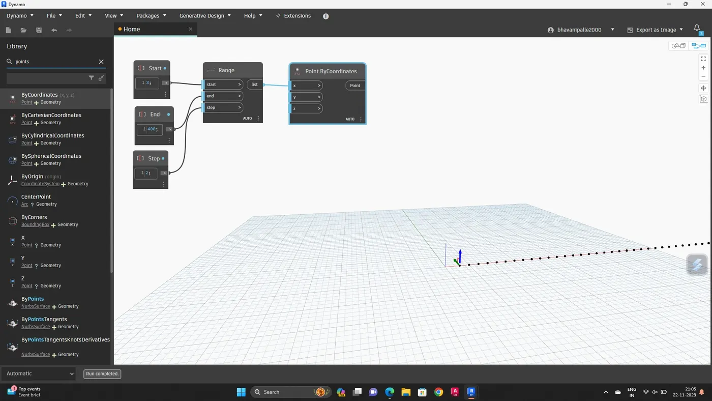
Search points by coordinates in search pannel, and insert
Then connect the range block to the X coordinate of the point by coordinate
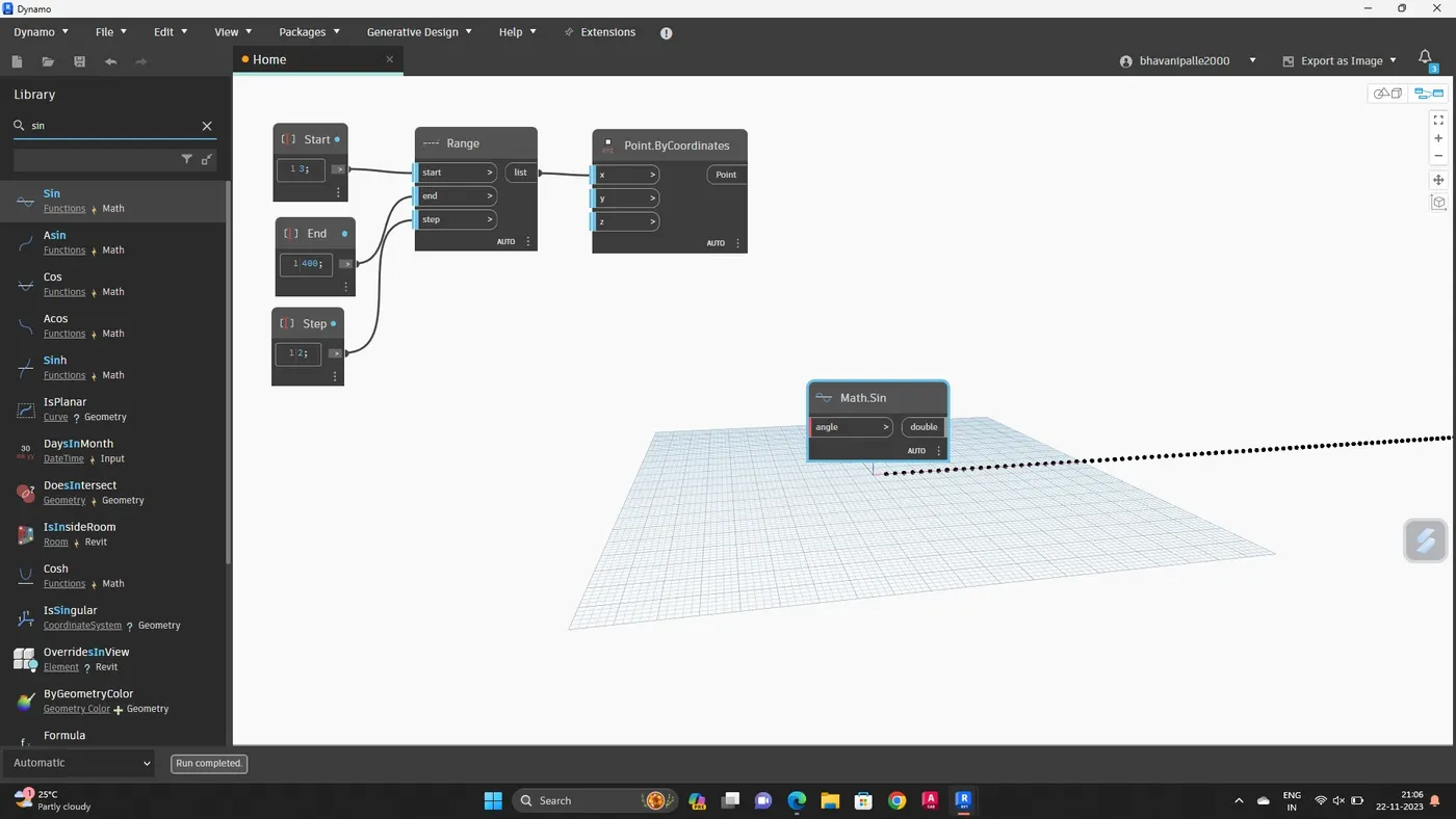
Now insert sin function which is given by math.sin option in the library
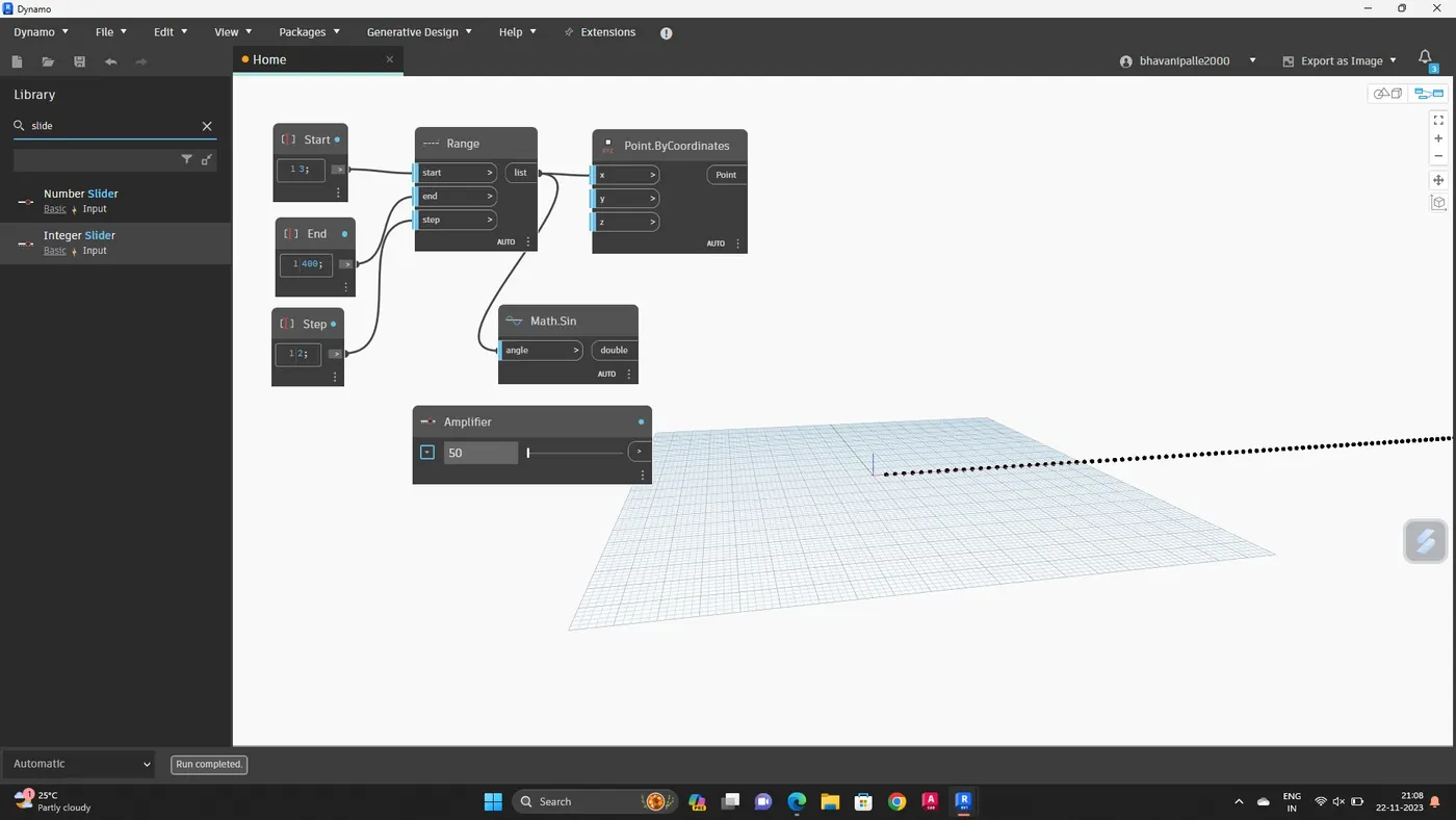
Sin values are small so, we need to amplify it. For that, insert slider and name it as amplifier, and give value
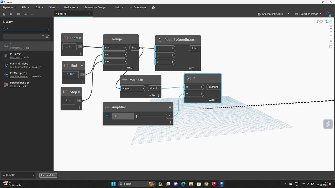
This amplifier code block needs to be multiplied to the sin block
For this, search product function in the library
Input for x value is sin block and for y value is amplifier
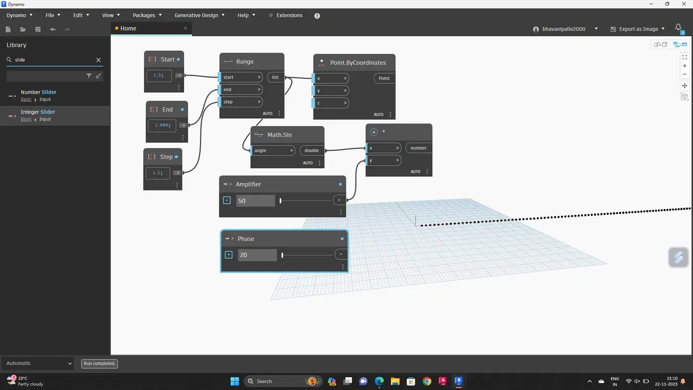
Provide phase for the sin curve
Insert an integer slider and name it as phase
Insert add operator block from library
Connect phase block to add operator, and add operator x to product block
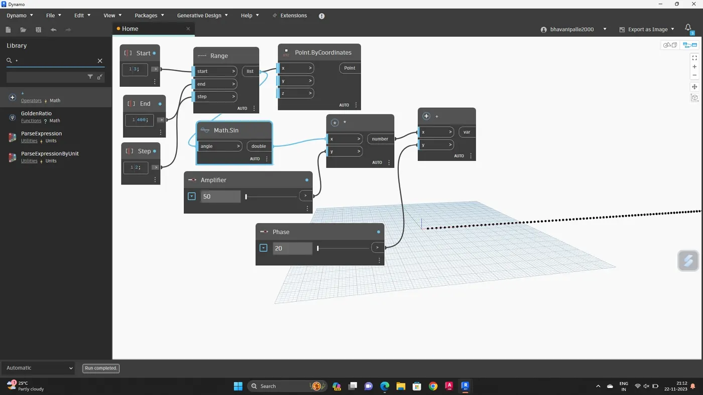
Now this is connected to the Y coordinate of the points by coordinates block
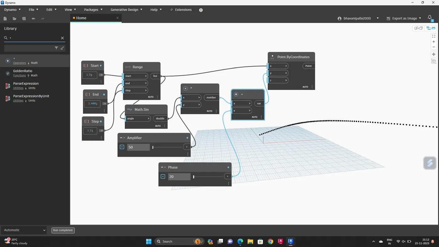
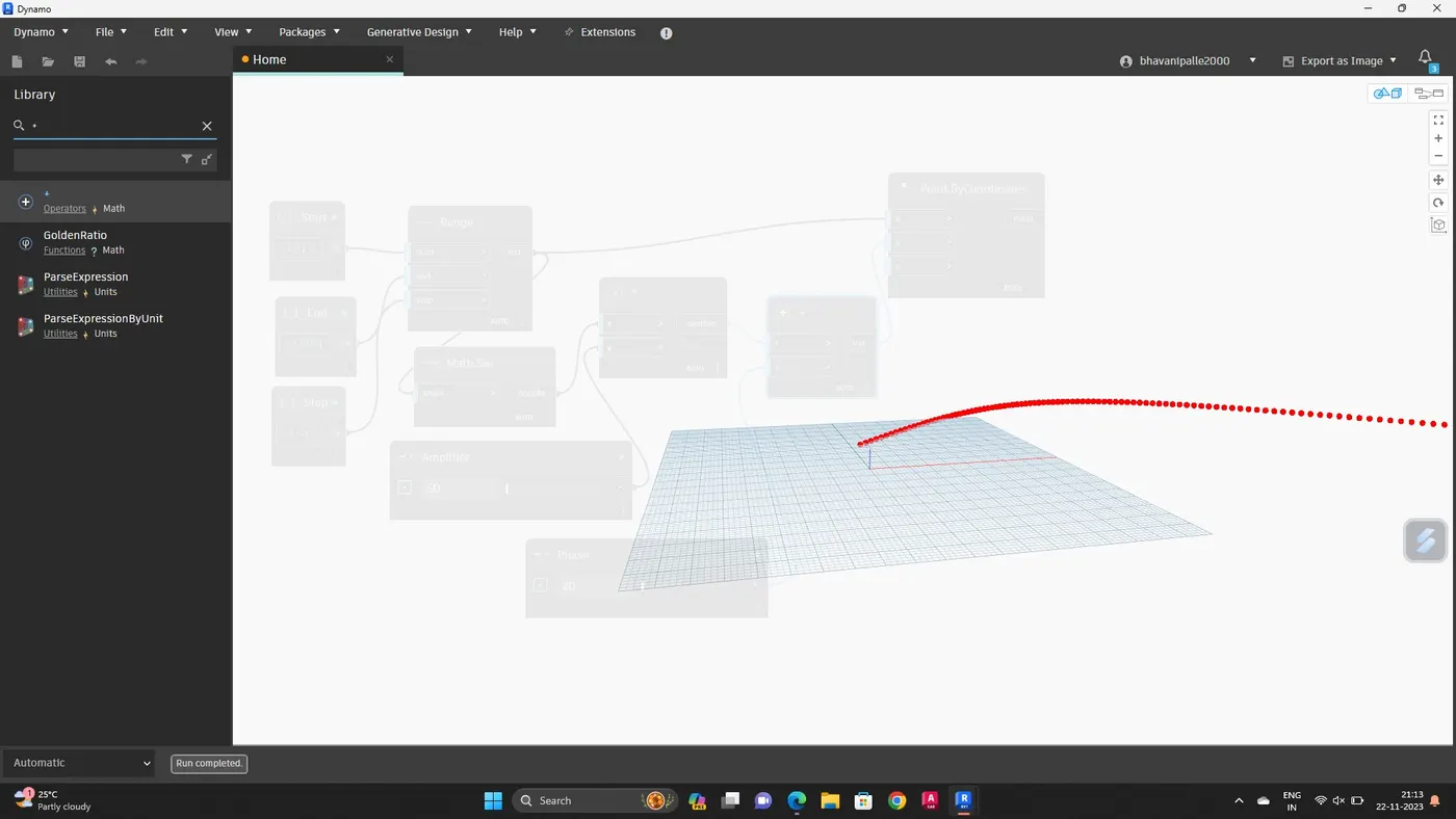
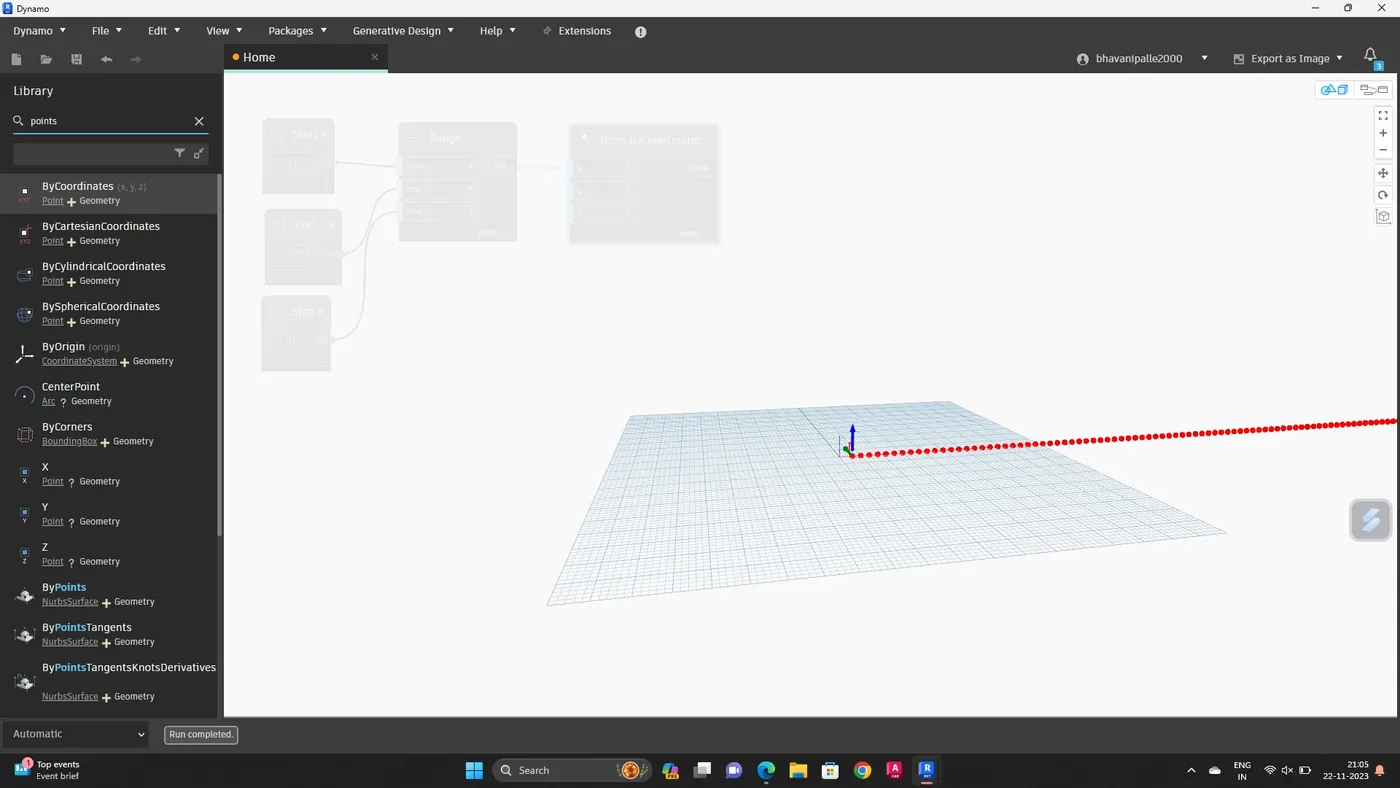
Set of sinusoidal points are obtained
Now we have to convert them to a curve
The curve can be created from nurbscurve
Search nurbscurve in library and choose nurbs curve by control points
Now, connect the points by coordinate block as input for the nurbs curve
A line will be developed connecting the points
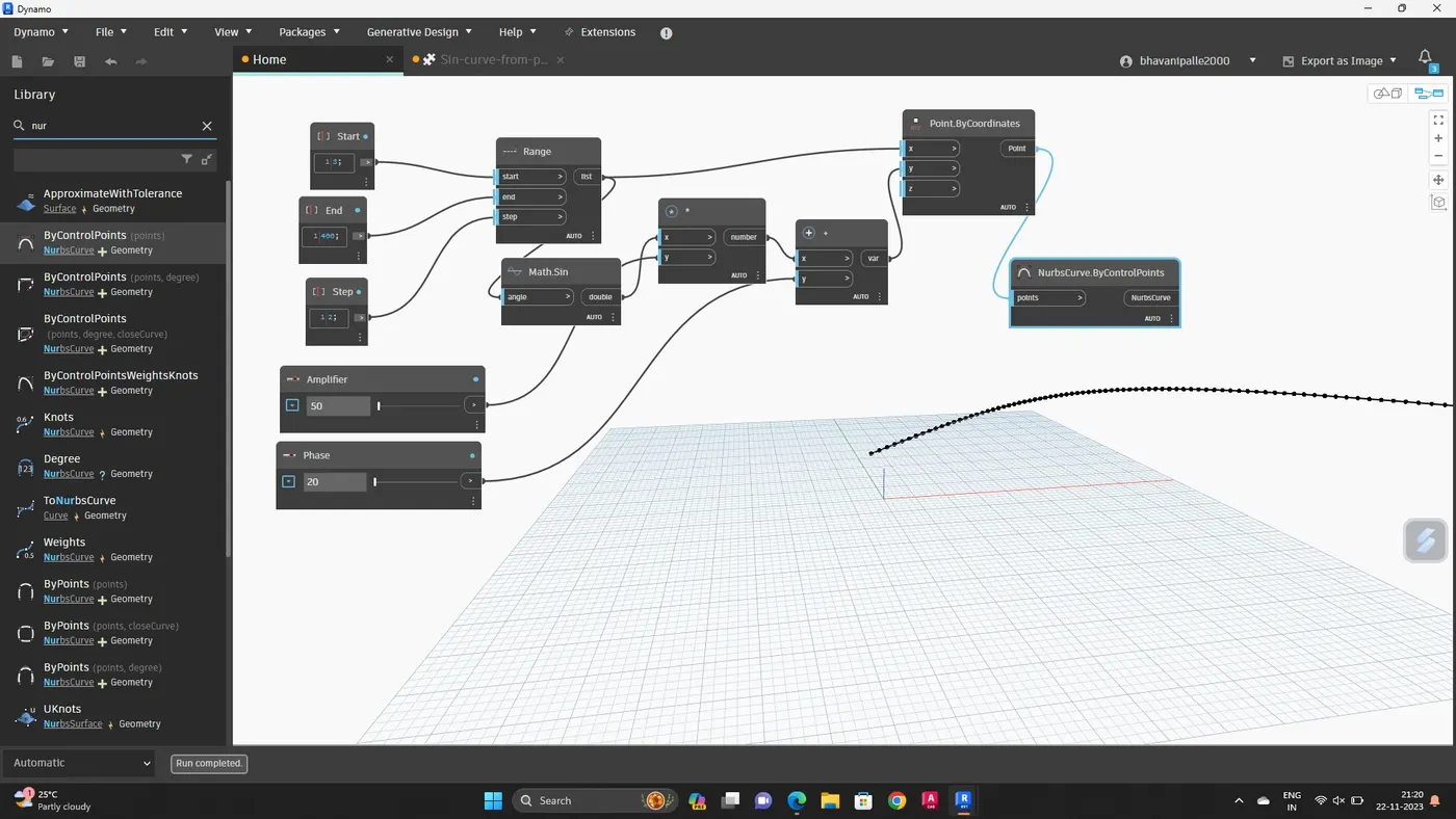
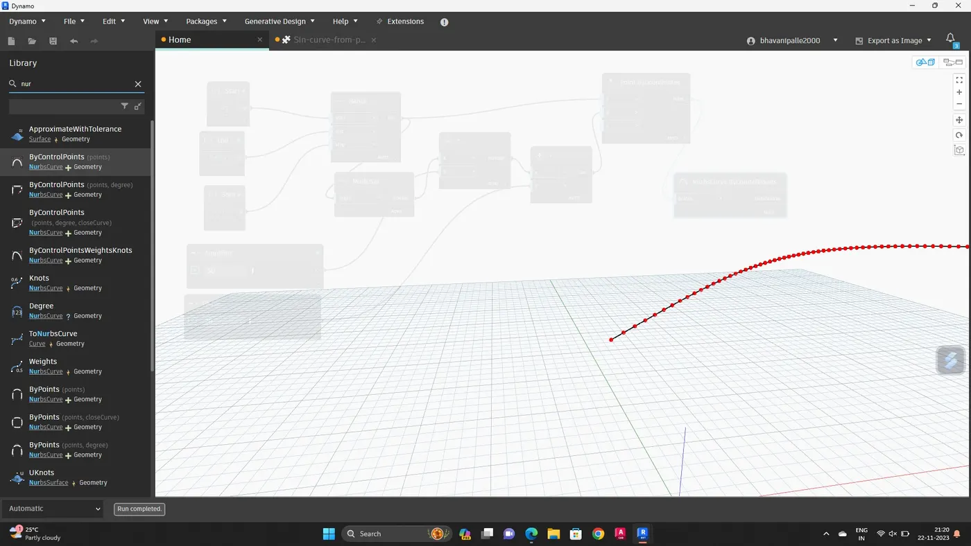
Sinusoidal curve is created
Now create a grop of these items for easy manipulation
This can be done by selecting required input blocks and then go to edit option in the top portion and then choose create node from selection
Entire thing will be grouped together
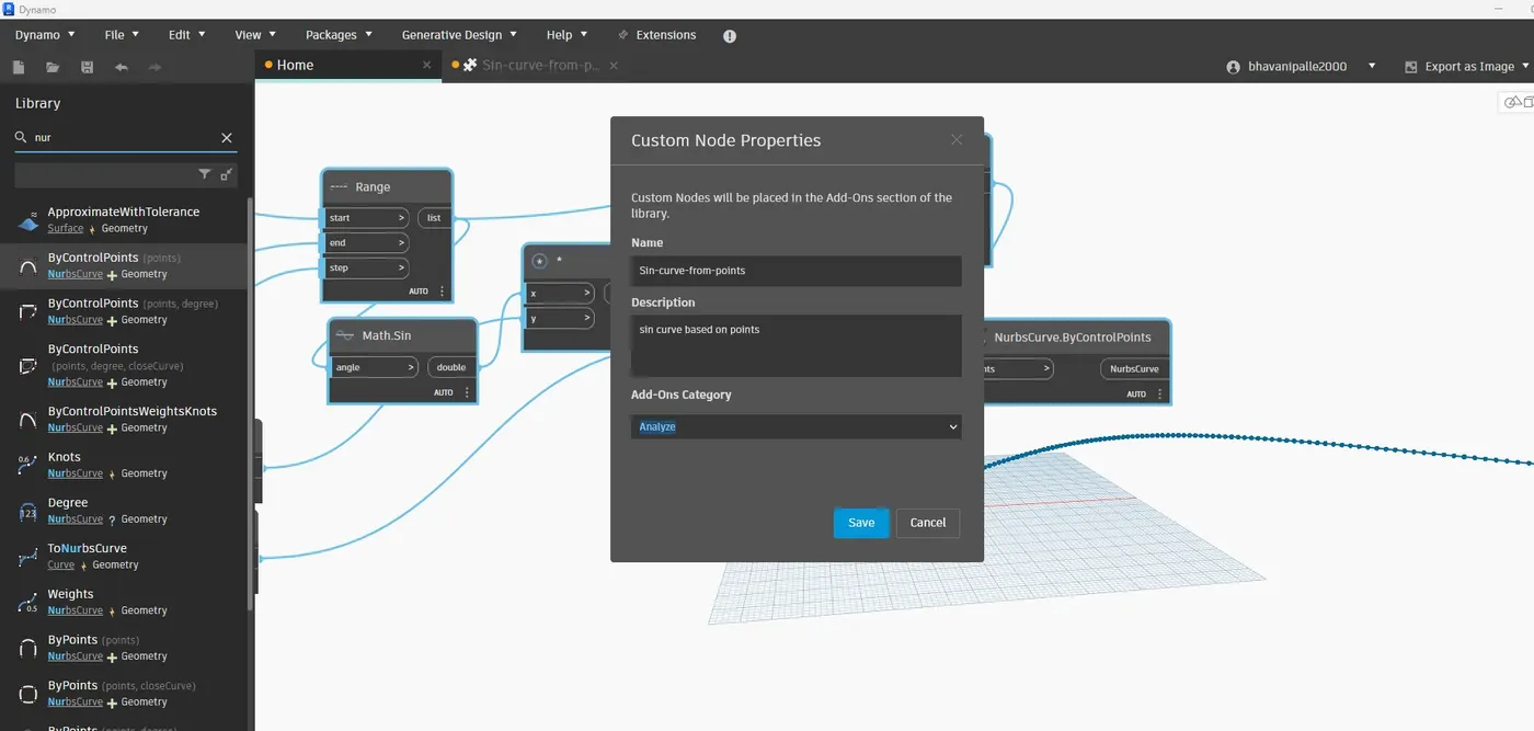
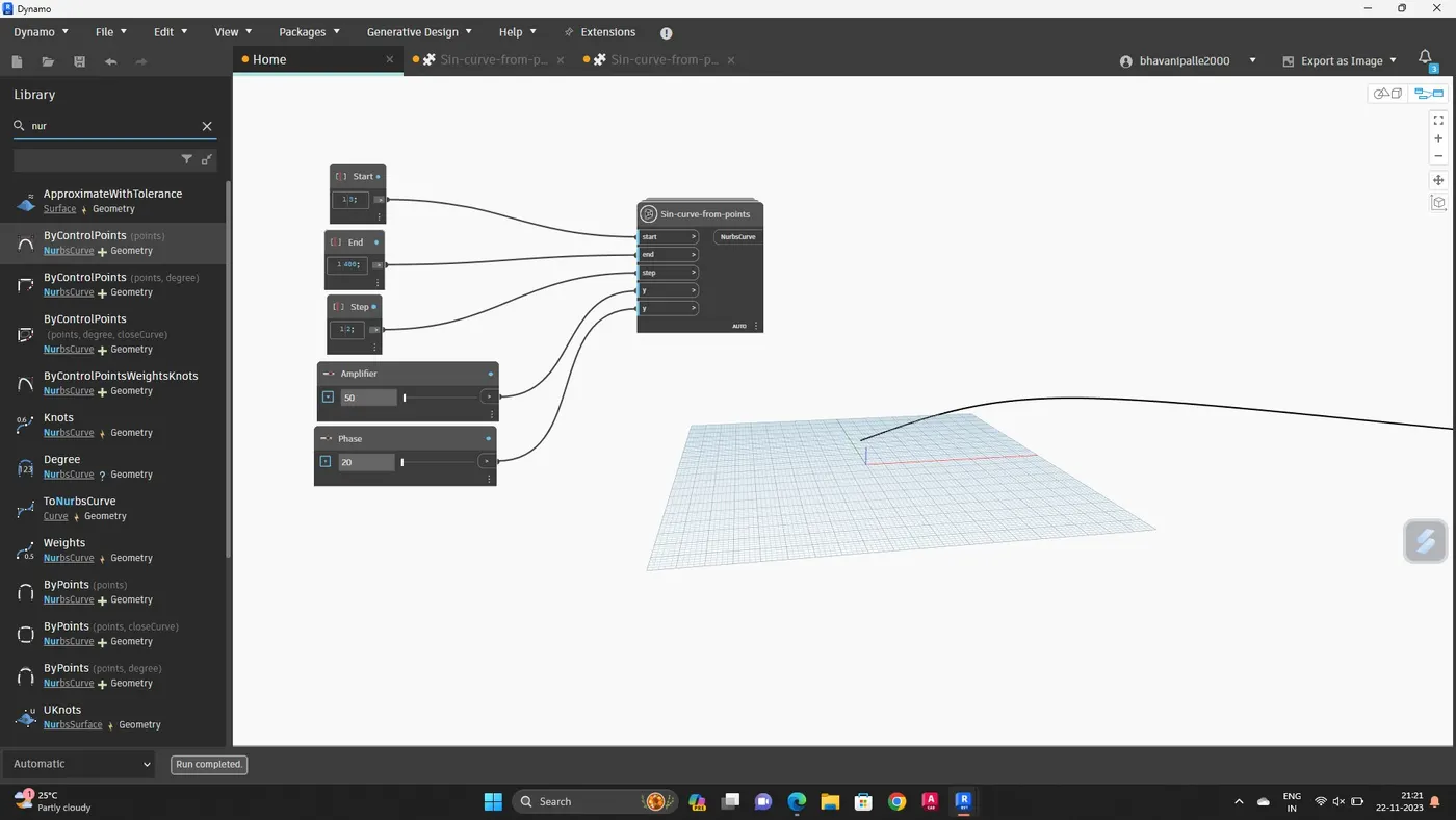
Now copy this entire blocks two times to create the surface
Adjust phase to view the two curves that is copied
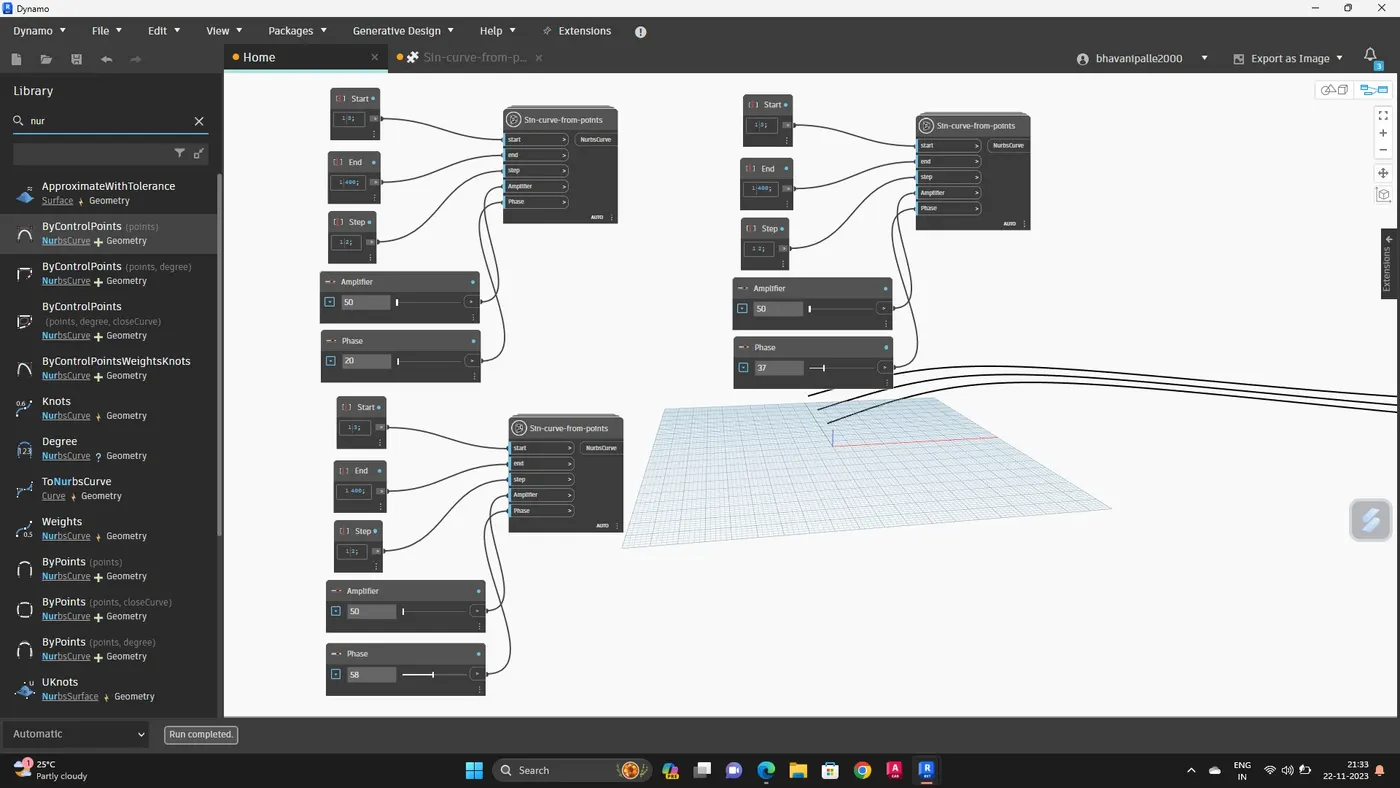
Create the surface
First create a list
Search list and insert
Connect all the output of the sine curves as input for the list
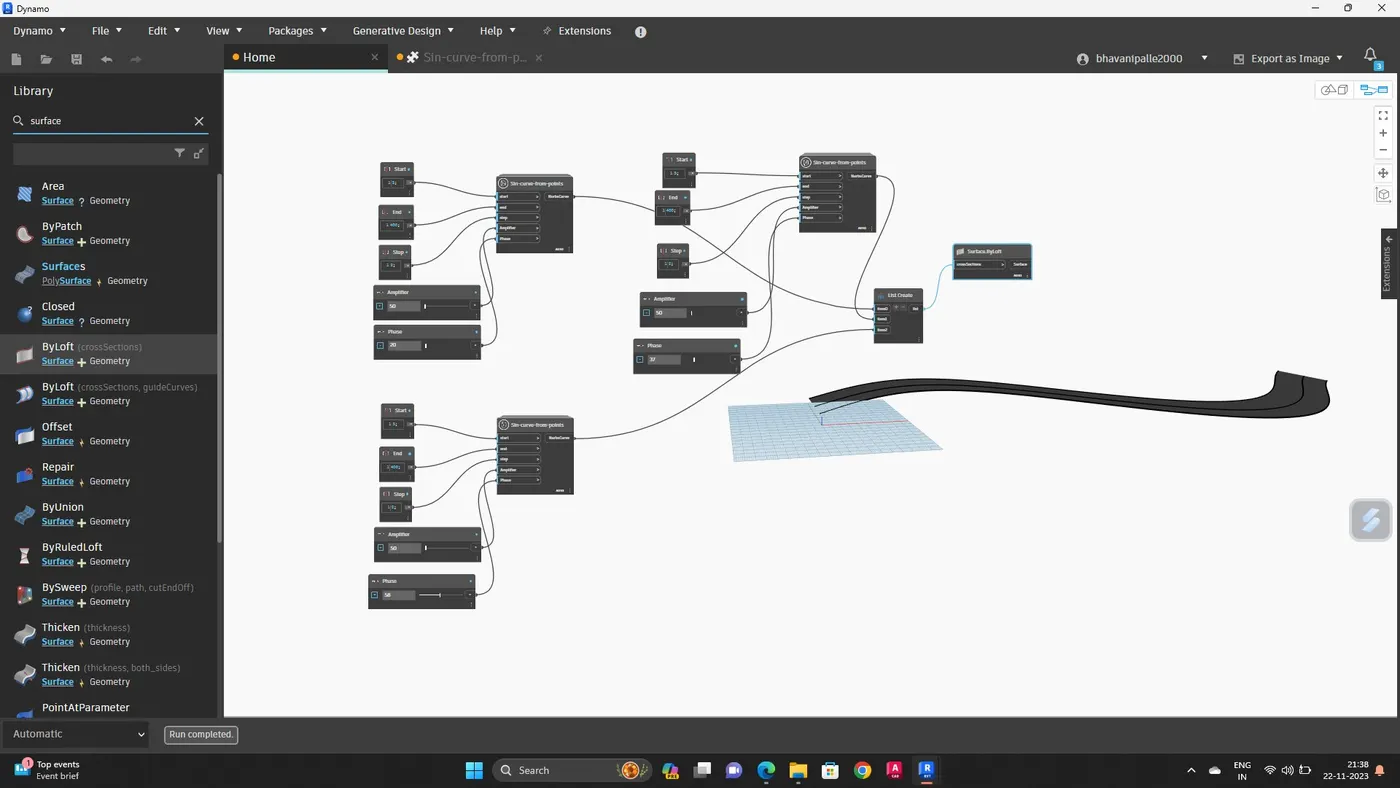
This will serve as input for surface by loft block
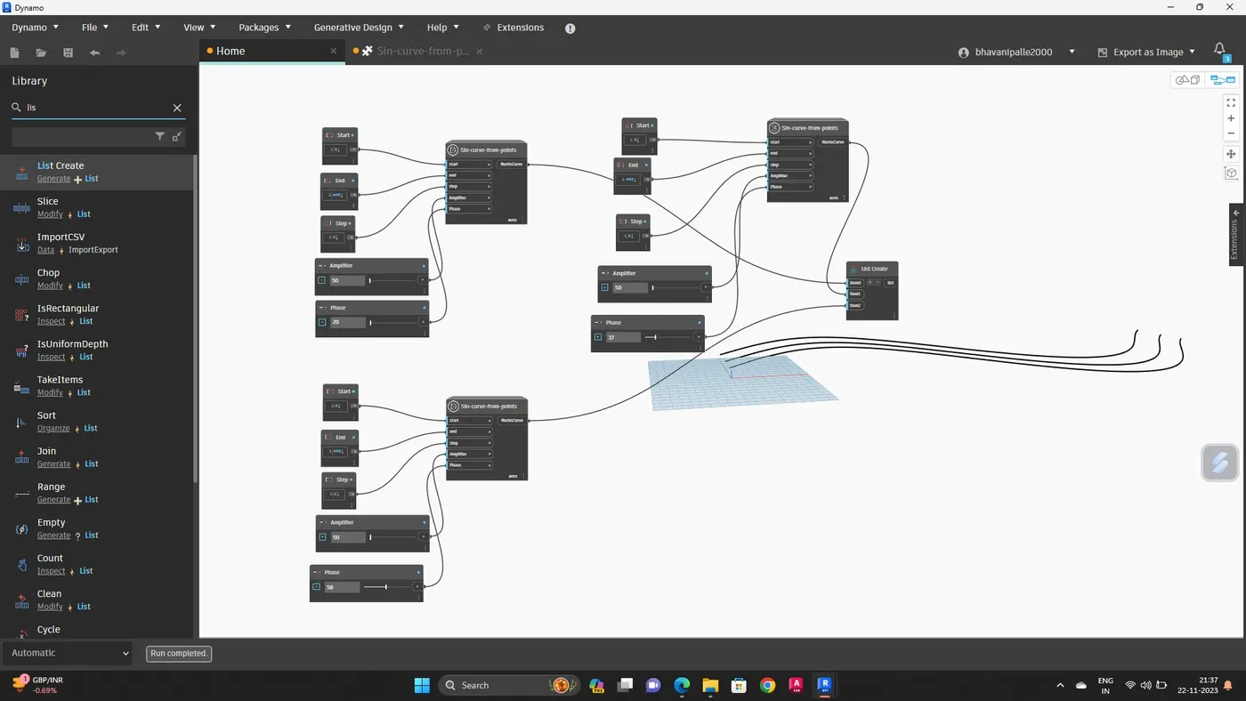
Now create the surface
For this, search surface by loft
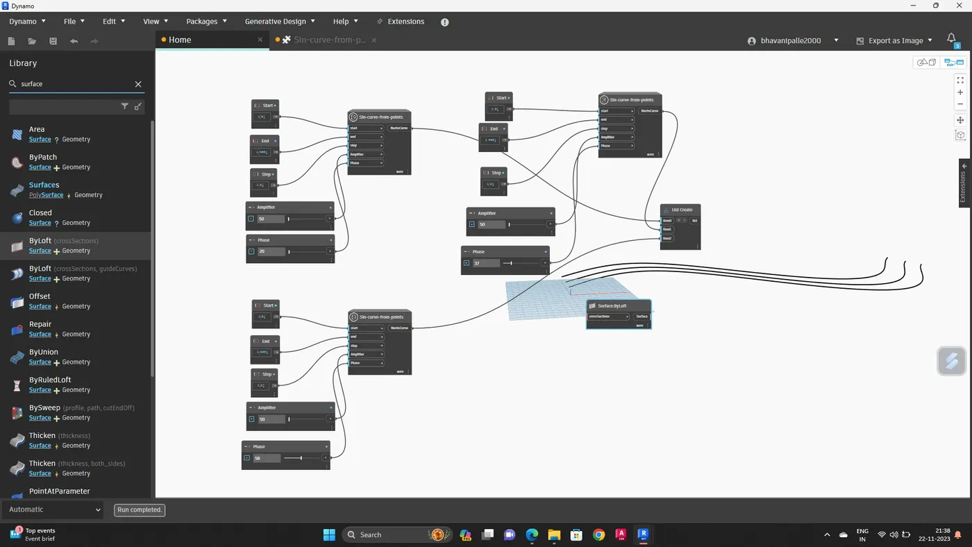
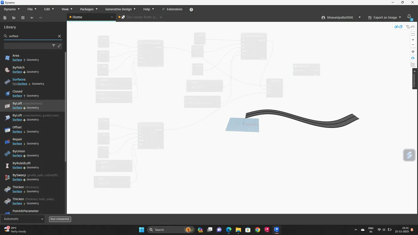
Hence surface is developed out of the curve
RESULT :
A set of sinusoidal points and curve has been created
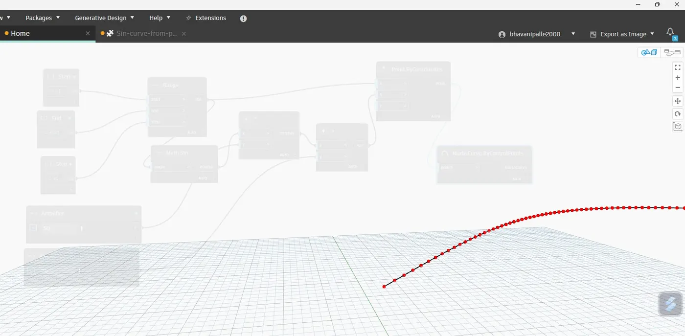
Surface is developed out of the curve
2. AIM :
To create a conceptual layout of a floor plan in dynamo
INTRODUCTION :
Dynamo is an open source visual programming language for Revit, written by designers and construction professionals.
Its a programming language that allows you to type lines of code; while also creating an algorithm That consist of nodes.
To create floor using wall types in dynamo, tools used are integer slider, code block, point by coordinates
PROCEDURE :
Open a new architectural template
Go to manage tab and open the dynamo, click on new
In order to create the wall first we have to create four control points
Search points by coordinates in library
Rename them as
Origin (0,0,0)
Control point 1(x,0,0)
Control point 2(0,y,0)
Control point 3(x,y,0)
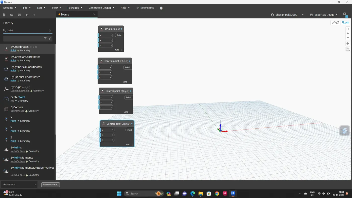
Provide two integer sliders to create the values for x and y
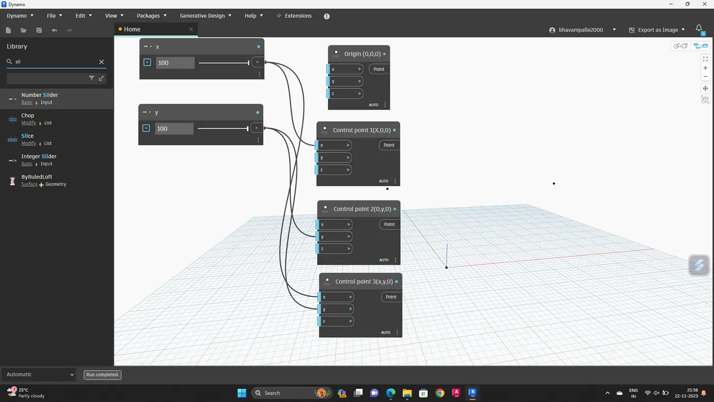
Connect these points by a line
Search line by start and end point and insert 4 blocks
Input of these blocks are the points created previously
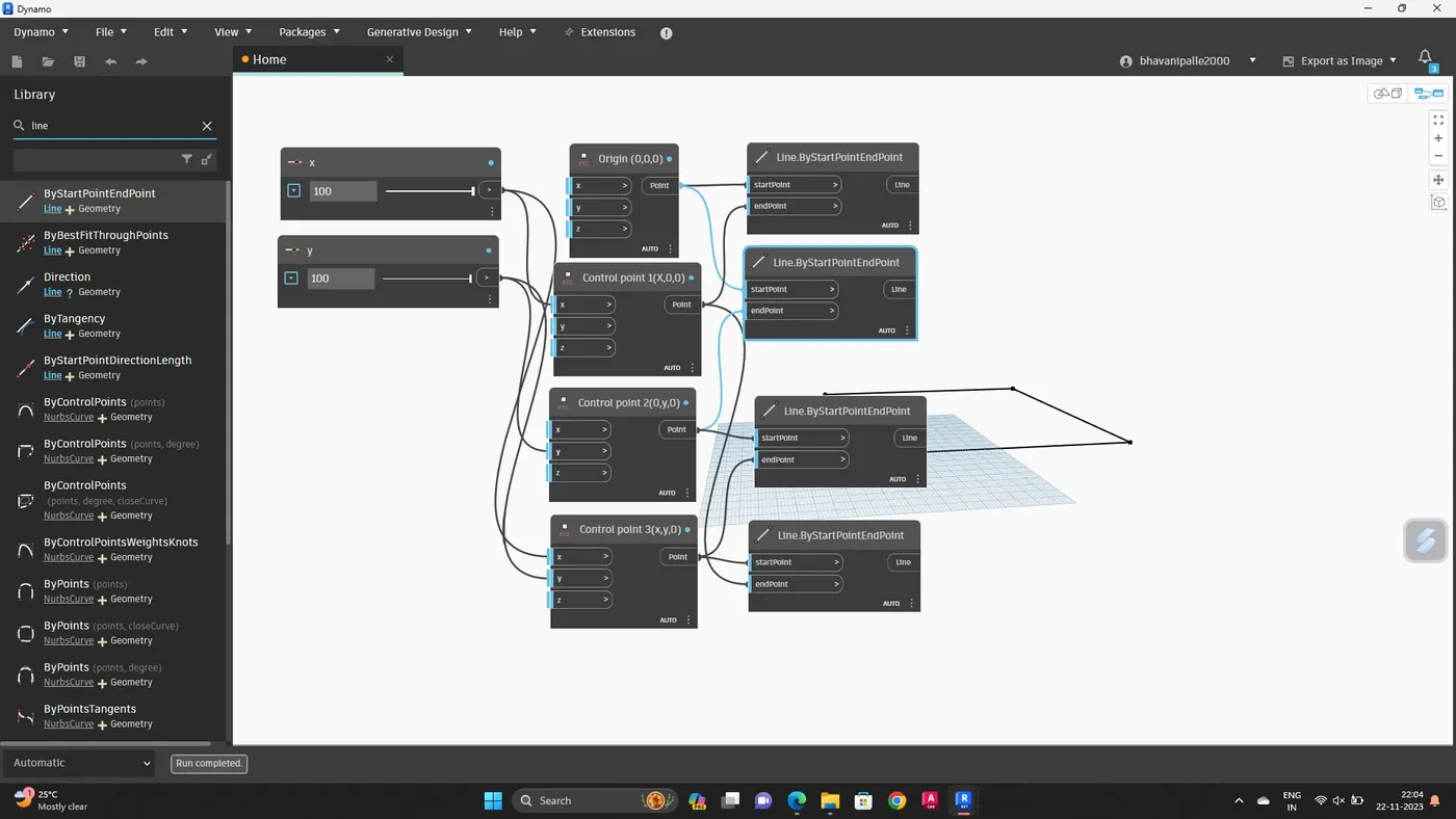
Hence layout of the floor plan is obtained
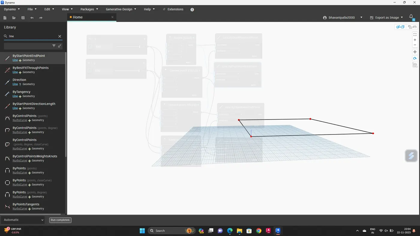
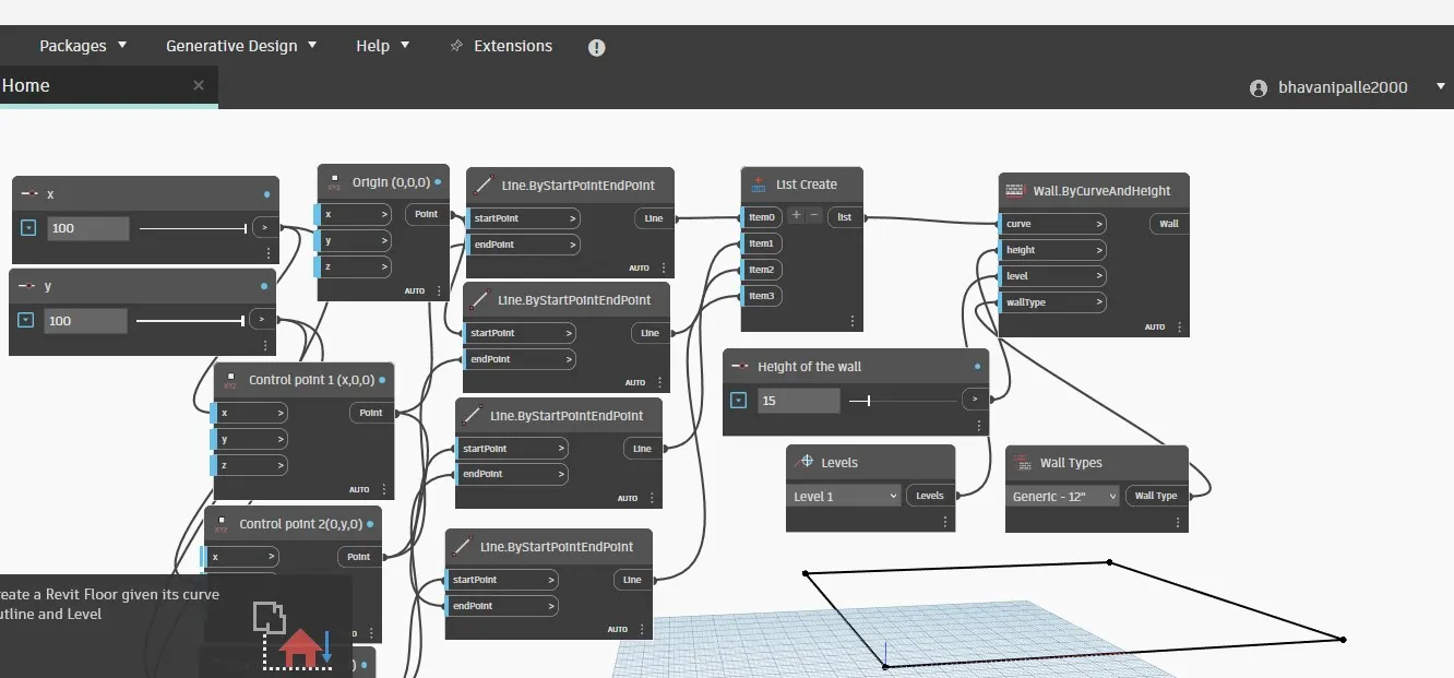
Next, add wall by curve and height
Combine all the four lines in a list by choosing list create
Height, levels, wall types are created
Connect all the input blocks to wall by curve and light block
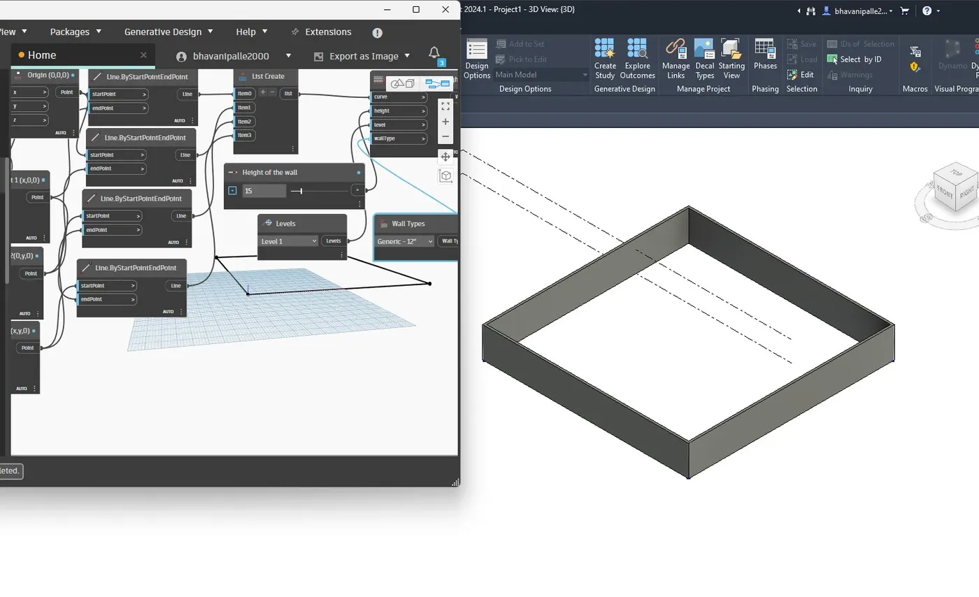
Go to revit architectural file, wall is visible
Now, provide floor
Type floor in the library and select floor by outline curve
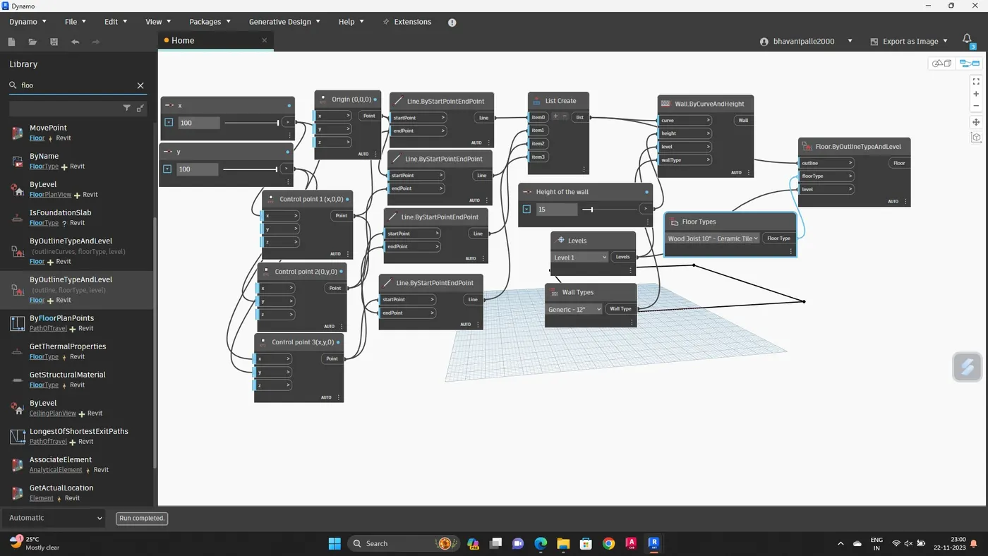
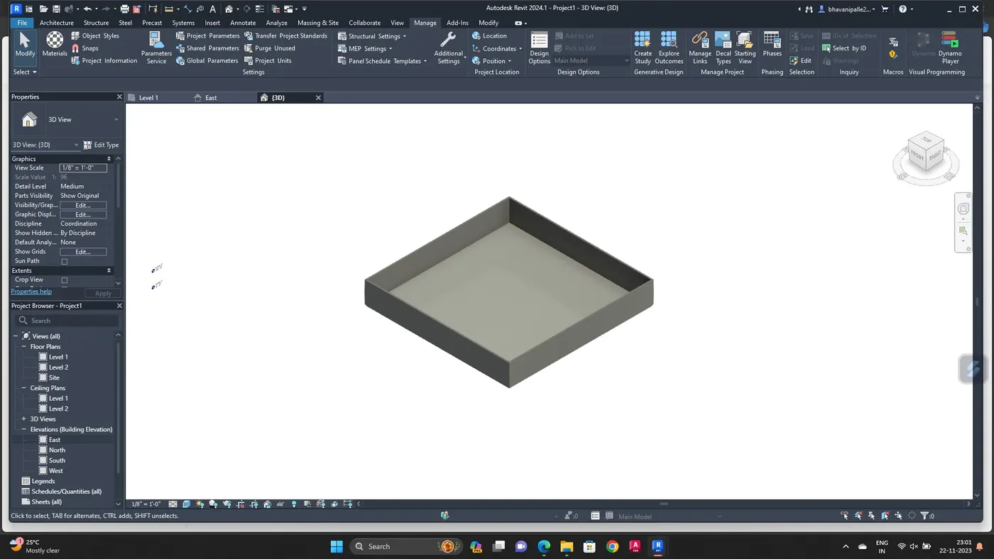
RESULT :
Conceptual floor plan layout has been developed
3. AIM :
To create an array of model elements in revit
INTRODUCTION :
The array tool creates a linear or radial array of selected elements.
Use array tool to create several instance of one or more elements and manipulate them simultaneously
Array members can belong to a group , you can add or remove items from the group
PROCEDURE :
Open a new architecture template
Go to architectural column, place the column
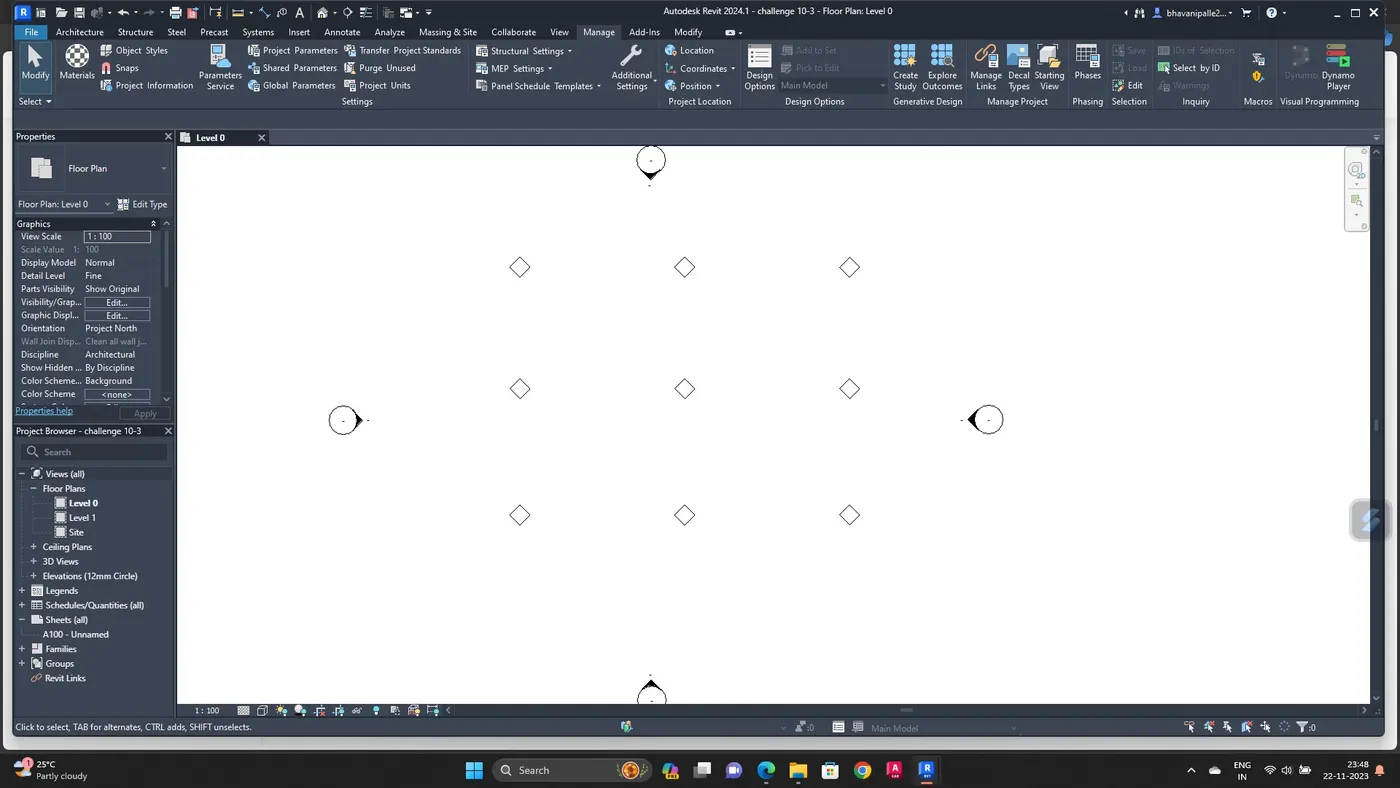
Similarly create 9 columns
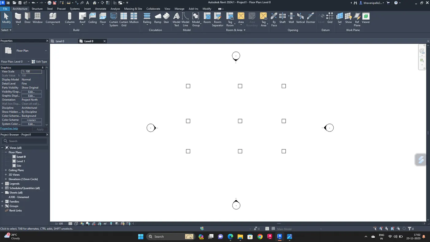
Open dynamo
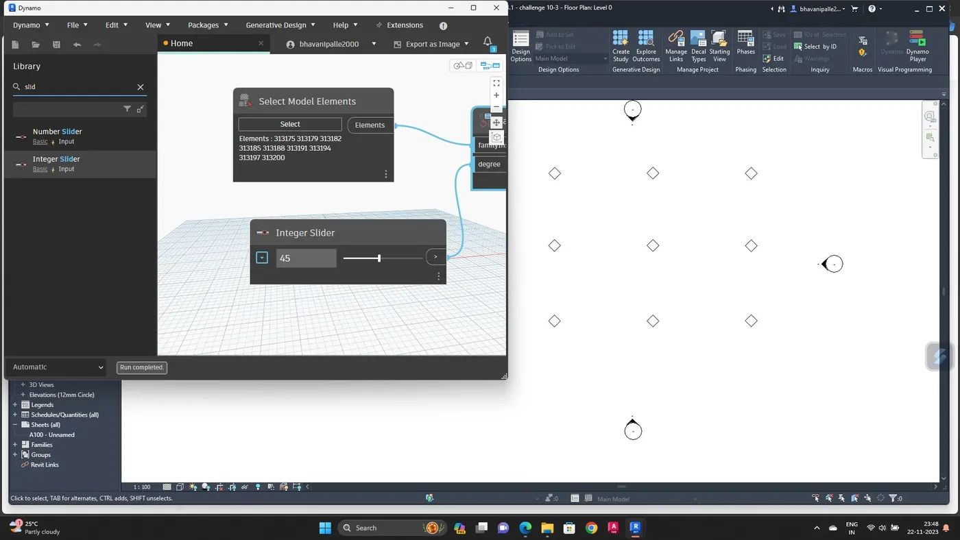
Search select model elements, integer slider, and set rotation
Rename the integer slider as rotation angle, and give some value
Now click select model elements, go to revit file select all the columns
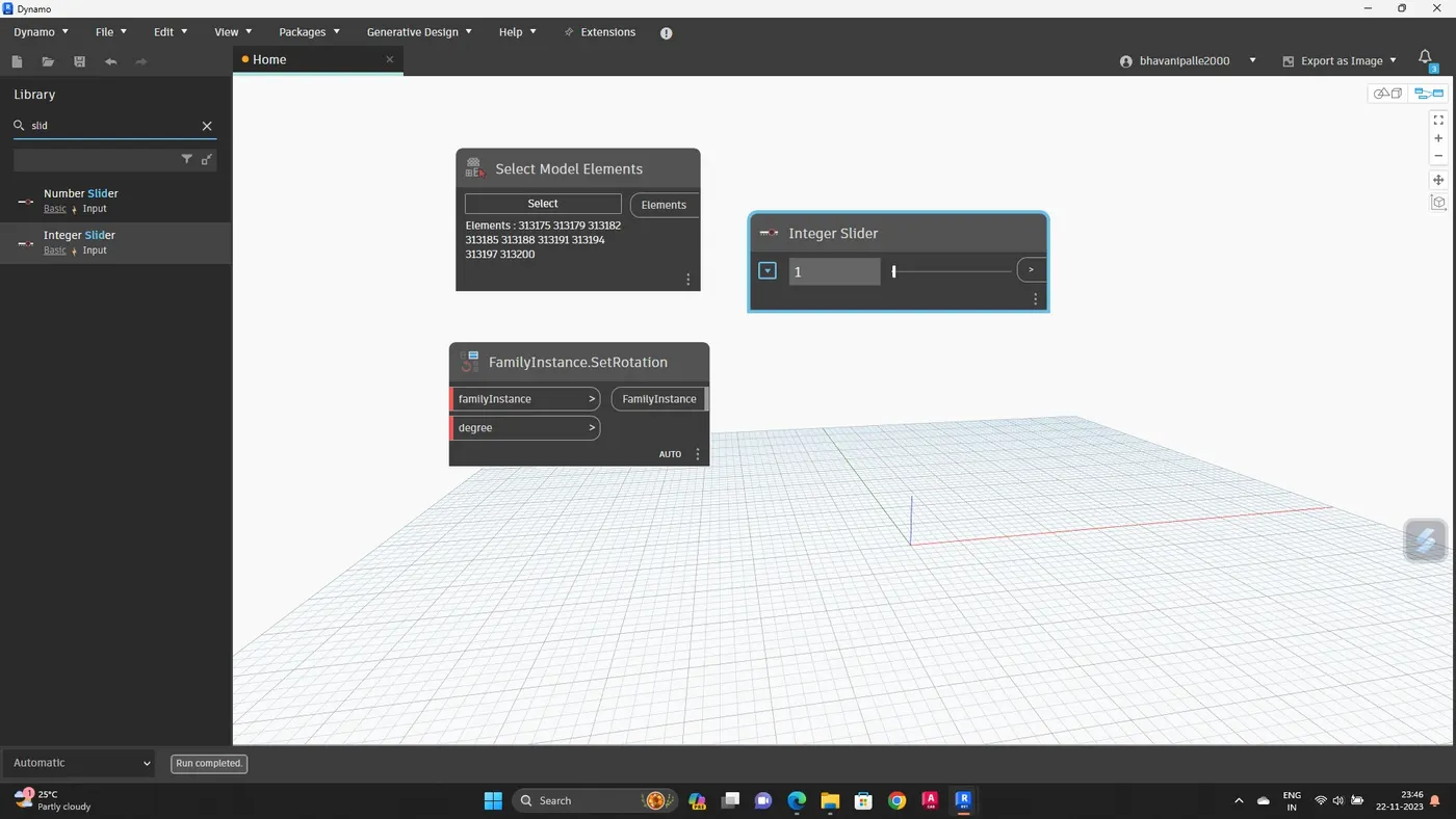
Connect elements to family instance and rotation angle to degree
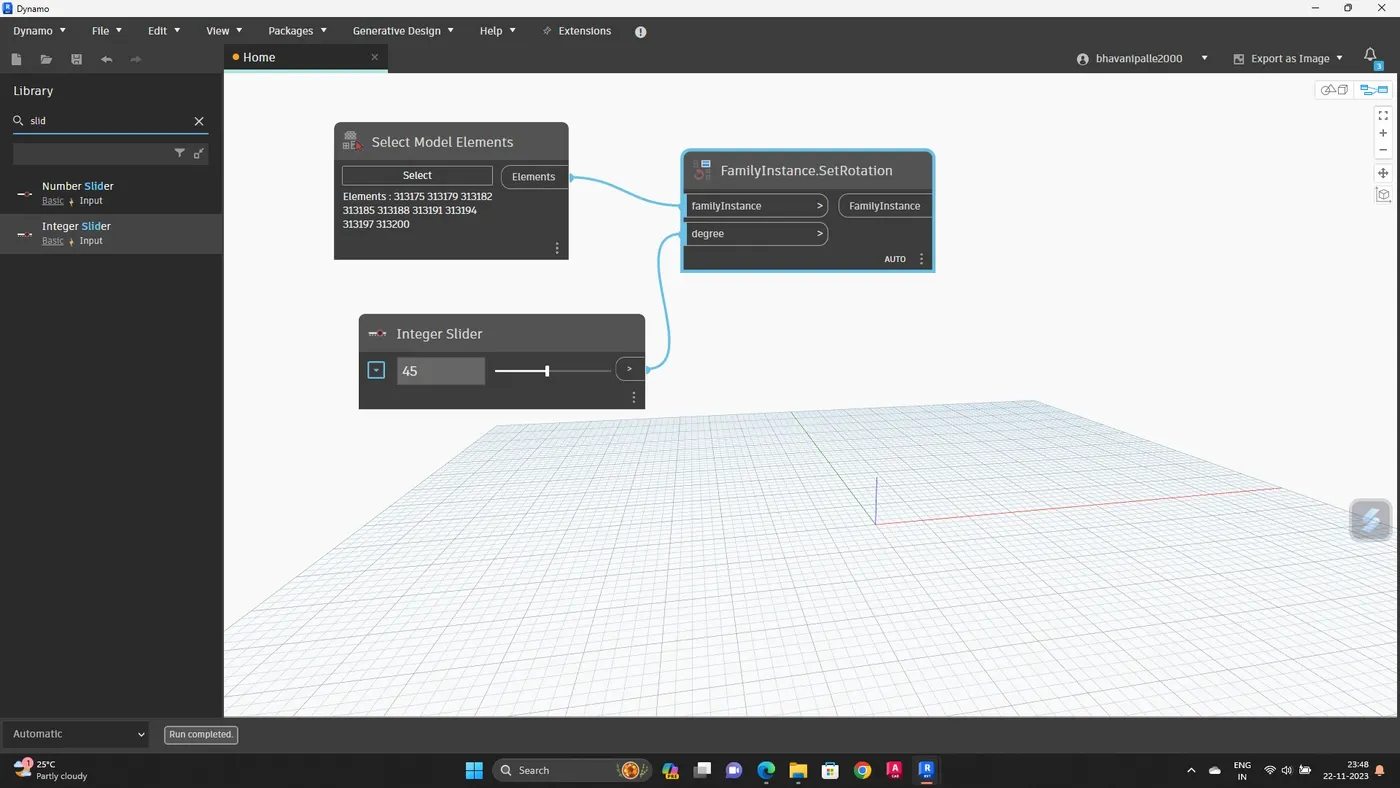
The rotation angle varied to desired value.
RESULT :
Array of model elements have been created and their roperties are being varied through the blocks created in dynamo
4. AIM :
To create a conceptual mass in revit and develop a parametric column by dividing the surfaces
INTRODUCTION :
Dynamo is an open source visual programming language for Revit, written by designers and construction professionals.
Its a programming language that allows you to type lines of code; while also creating an algorithm That consist of nodes.
Creating conceptual mass families means that the mass is external to the project, it uses same tools to create family, then saved and loaded into the project
PROCEDURE :
Open revit software under the families open new- conceptual mass-mass
Now go to elevation view and create a level
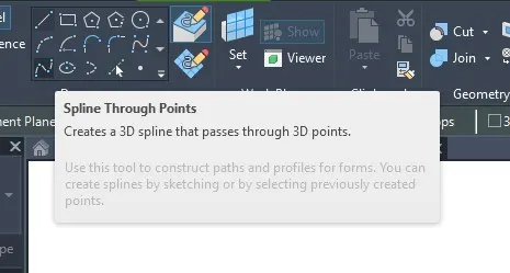
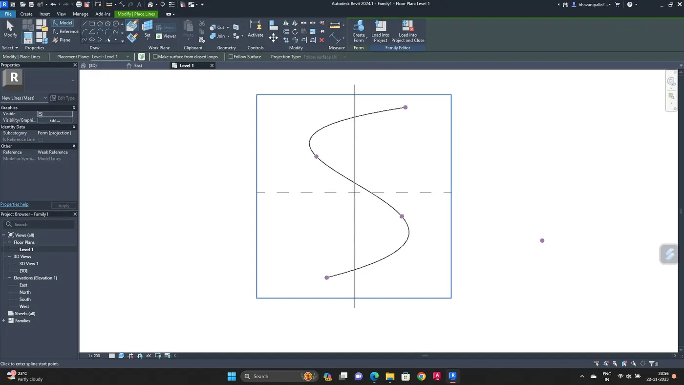
Now using spline tool draw the desired outline for the walkway
Now create a profile to sweep through curve
For this, we have to set the workplane at the points and develop a polygon at workplane keeping the point as center
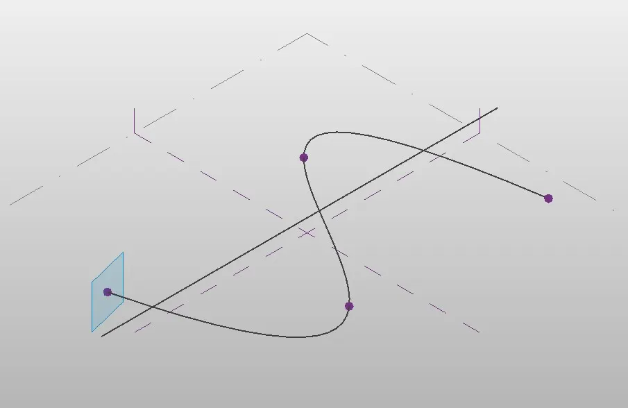
Polygon developed with point as center
Similarly develop polygon at all the nodes
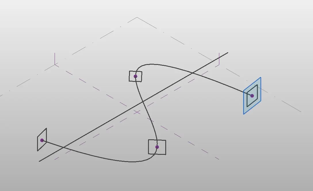
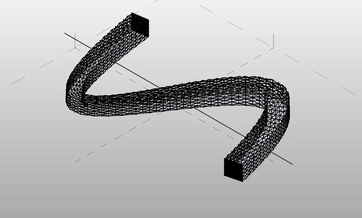
Now create Sweep, select all the polygons and the curveline and choose create form option
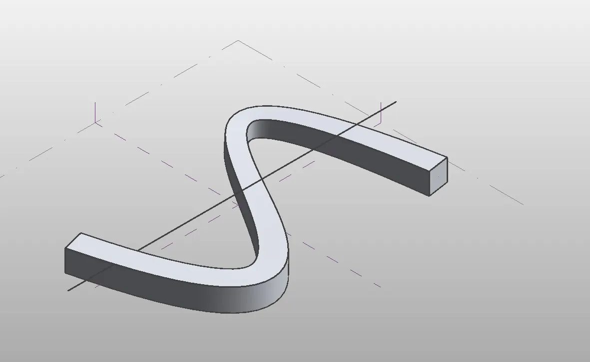
Select entire form and then filter and retain only the form
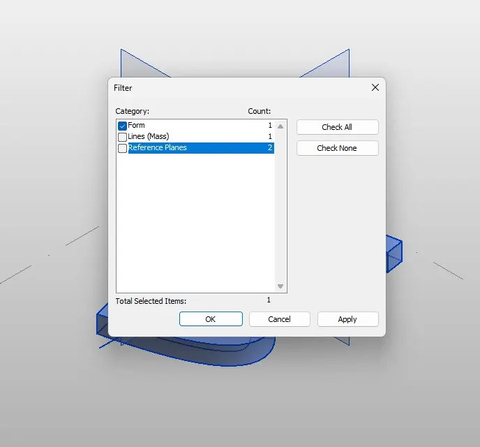
Now select form, divide surface, then provide the pattern triangle bent
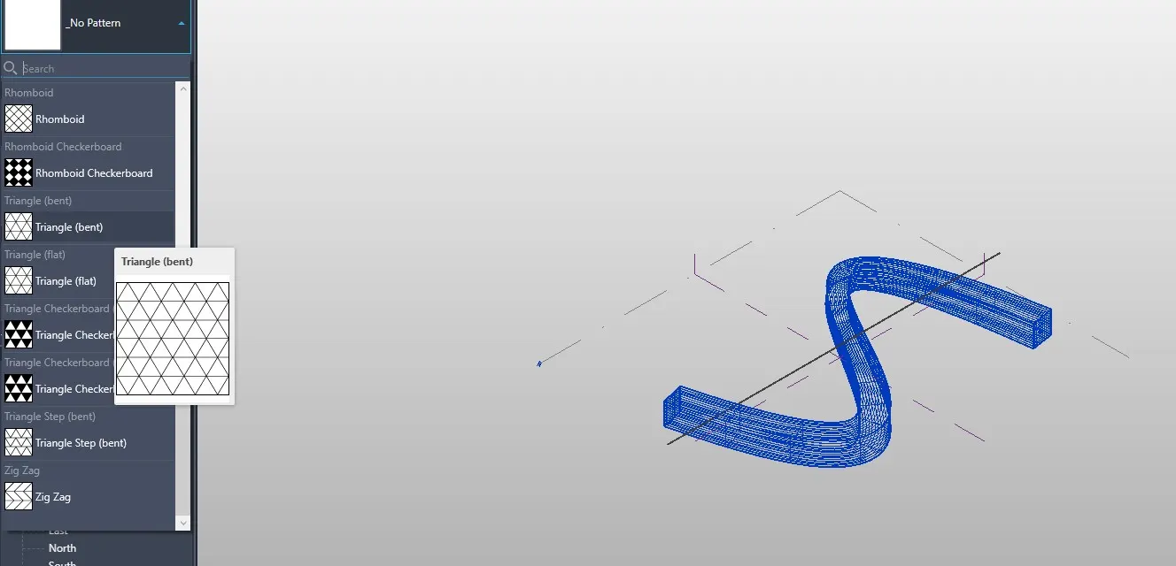
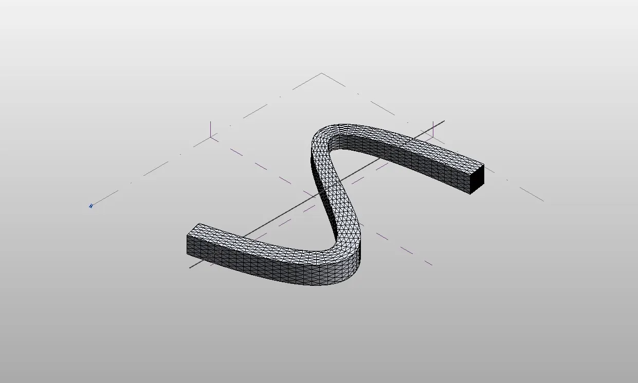
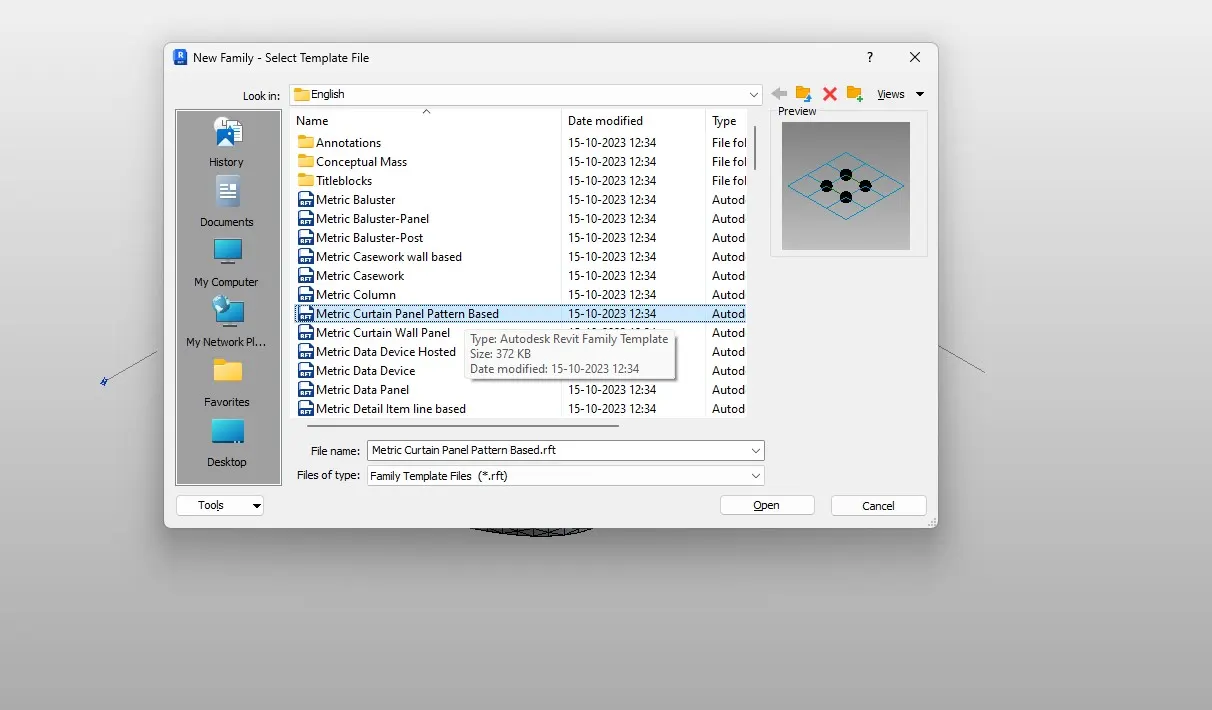
Now open a new family
Curtain panel based
Now select the pattern as triangle bent
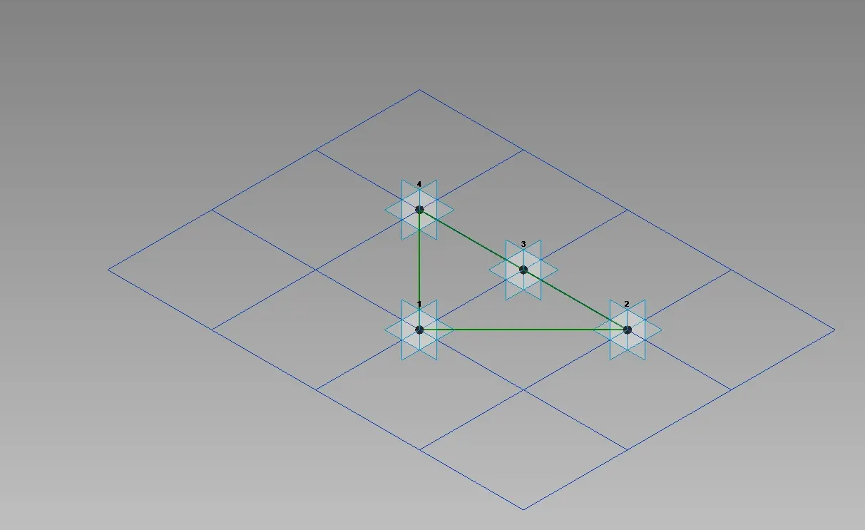
Create a reference point at midpoint of the face
Then draw a circle of radius 3'' at that reference point
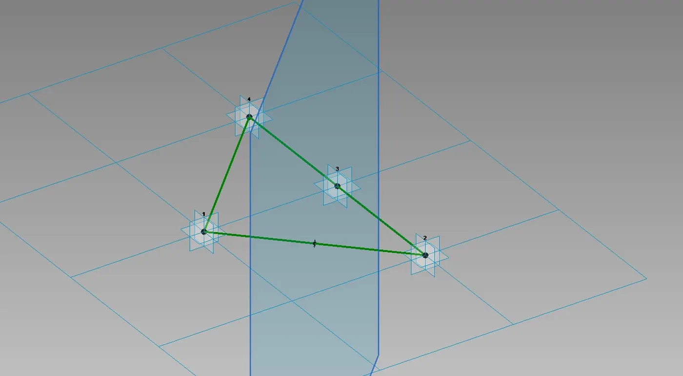
Now select pattern, reference plane and circle created
Create a form
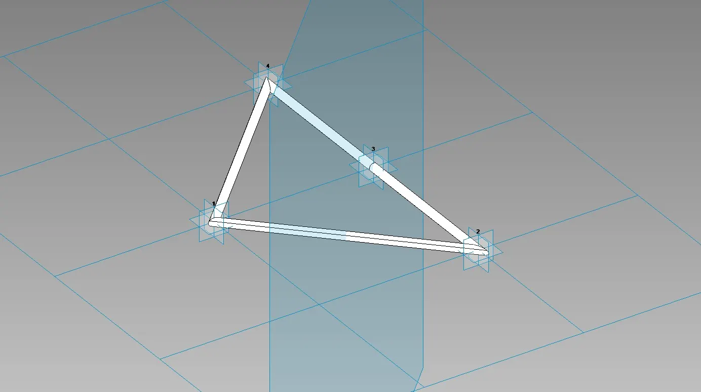
Now load this into the project
Select the entire formof the walkway and filter it to retain only the divided surface
Then in the pattern select the family that we have created
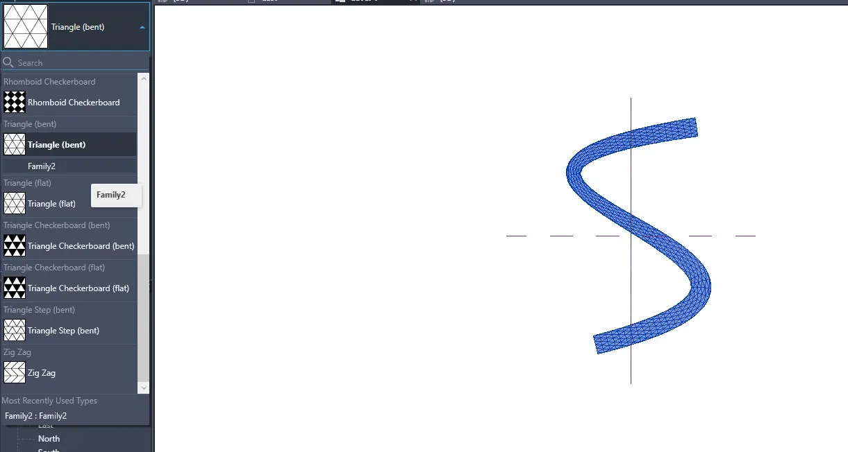
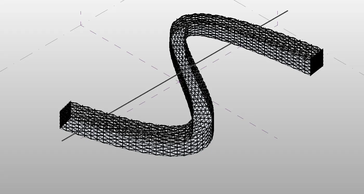
RESULT :
The conceptual mass have been created in revit
5. AIM :
To develop a parametric stadium using dynamo in Revit.
INTRODUCTION :
Dynamo is an open source visual programming language for Revit, written by designers and construction professionals.
Its a programming language that allows you to type lines of code; while also creating an algorithm That consist of nodes.
Creating conceptual mass families means that the mass is external to the project, it uses same tools to create family, then saved and loaded into the project.
PROCEDURE :
Open new architectural template, then open dynamo
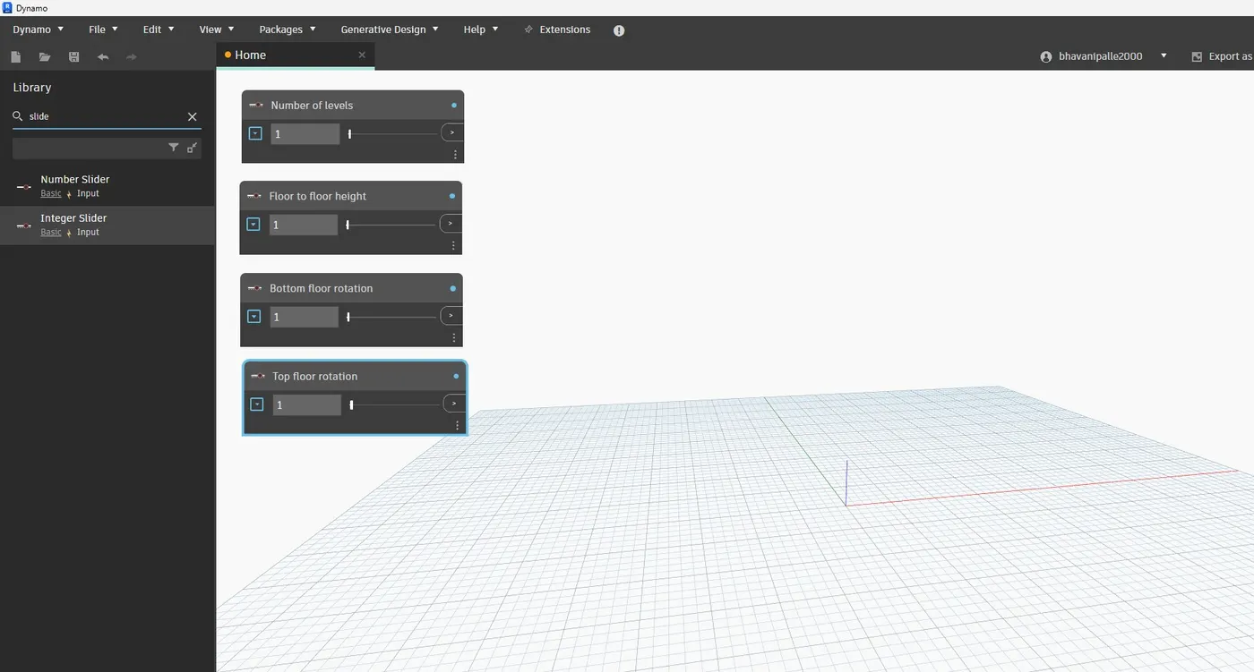
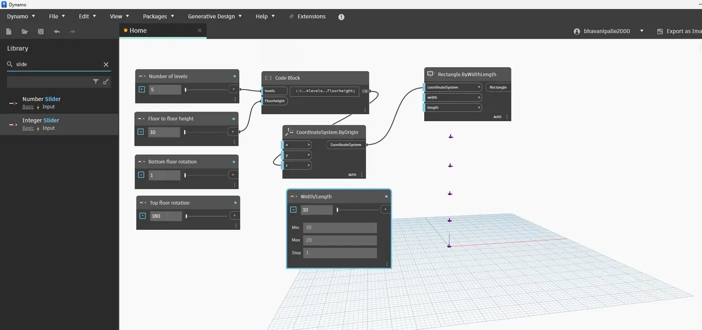
Four integer sliders is taken from the library for the following:
Number of levels
Floor to floor height
Bottom floor rotation
Top floor rotation
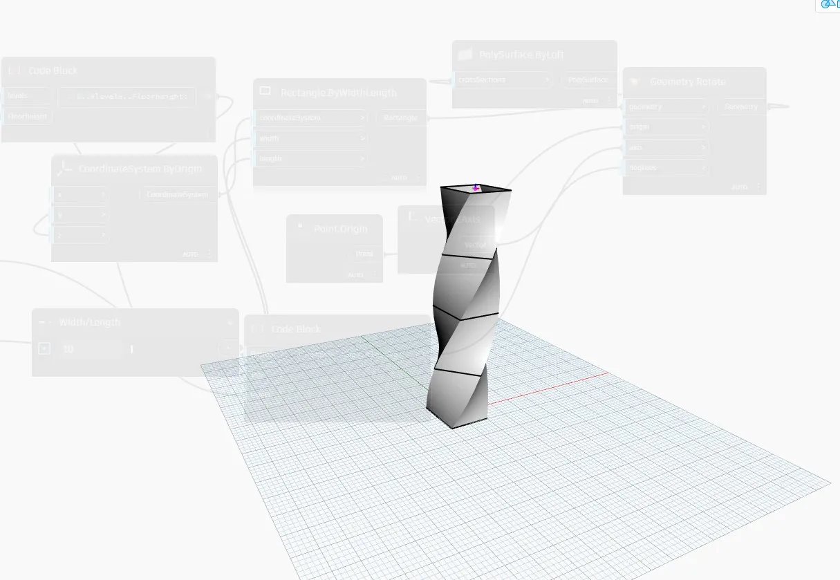
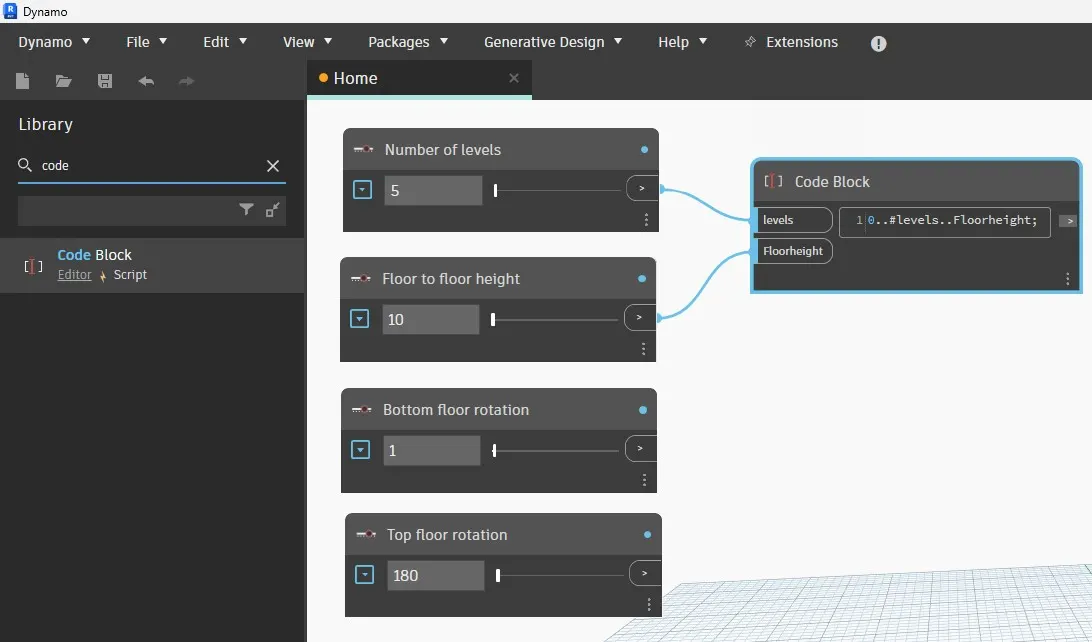
Now, insert a code block from the library to combine level and floor to floor height and type 0..#levels..Floorheight.
Now, connect the integer sliders named as levels and floor to floor hegiht as input to the code block.
Now, search coordinates by origin in the library and insert it.
Then connect the code block as input for z coordinate in the coordinate by origin block.
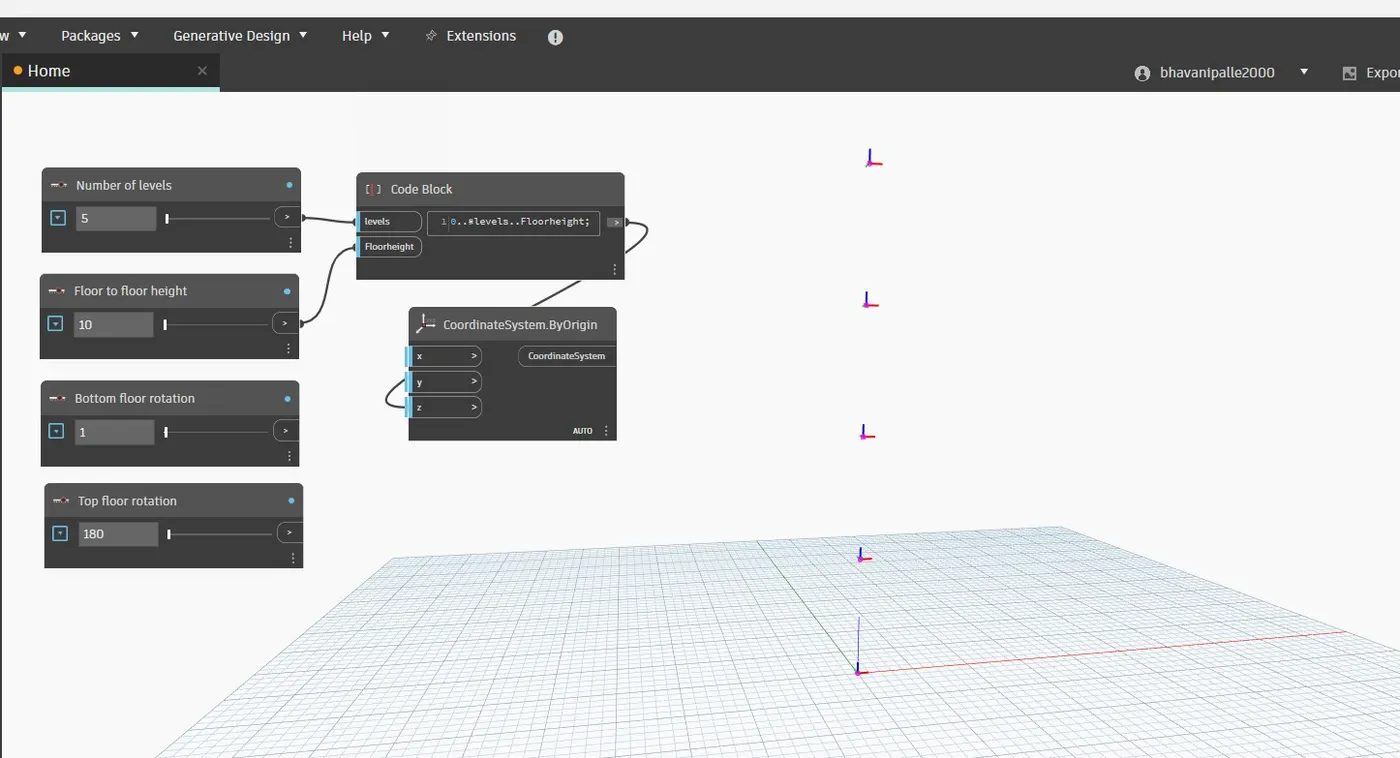
Five points are generated corresponding to 5 levels.
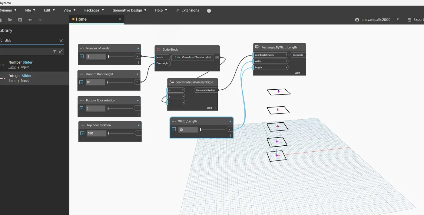
Now, insert rectangle by width and length from the library.
For this, inputs required are coordinate system, length and width.
So insert integer slider for length and width.
Then connect the inputs for the rectangle block
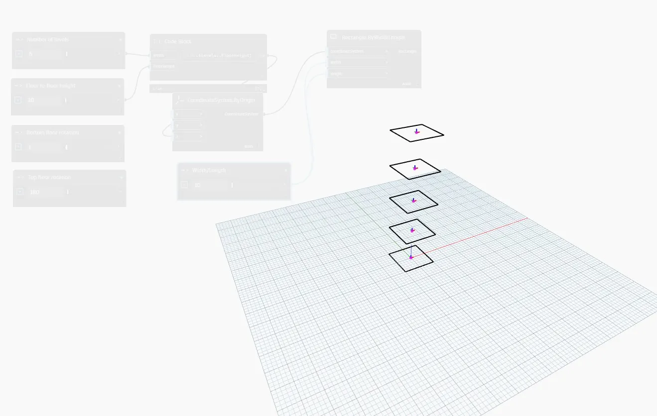
Now, we have to create surface, for this type surface by loft in library
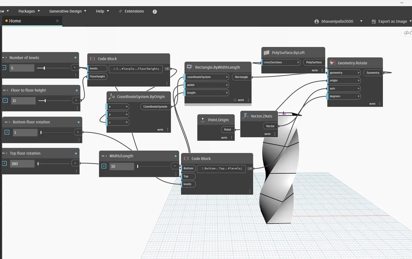
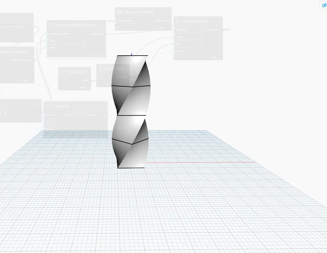
Now we have to rotate the geometry.
So, for this insert the rotate block from the library. The inputs required are:
Geometry : Rectangle block
Origin: insert an origin block from the library.
Axis: insert vector Z axis from the library.
Degrees: For this insert a code block and type Bottom..Top..#level.
The inputs for this code block is already available i.e, Bottom floor rotation, top floor rotation and levels.
RESULT :
The Parametric Stadium have been created