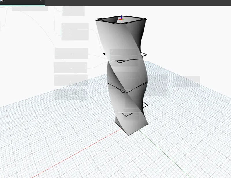
Creating Conceptual mass in REVIT and Creation of Sinusoidal curve and a Parametric stadium using Dynamo
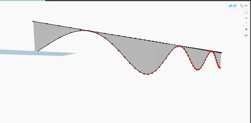
1) Using Dynamo creates a set of sinusoidal points and creates a curve and create a surface out of the curve.
ANSWER=
AIM: To Use Dynamo and create a set of sinusoidal points and create a curve and create a surface out of the curve.
PROCEDURE:
1. Just open thy Dynamo
2. In order to create the sinusoidal point first we need to insert the integer slider into the dynamo screen
3. Insert the 3 integer slider
4. Considered one of it START, END, and STEPS for making the sinusoidal curve
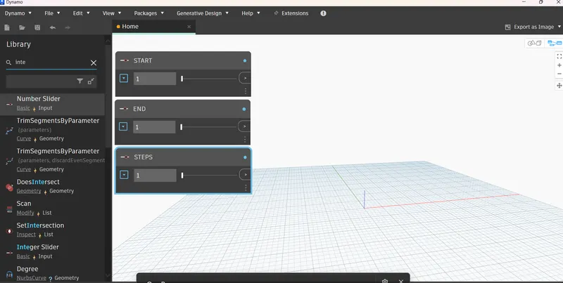
5. Once you have created the integer slider we need to create the range
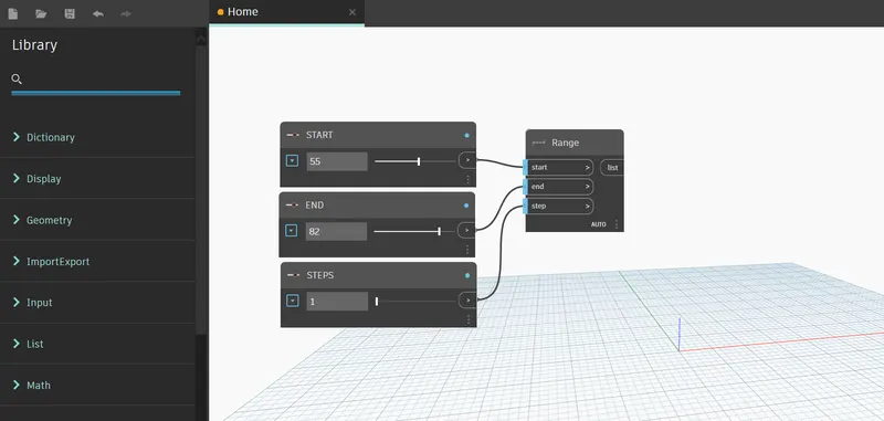
6. Then connect the respective slider to their respective input
7. Now the very next step is you need to Create a point-by-coordinate option
8. we need to make another point-by-coordinate and a code block to make the dual sinusoidal point
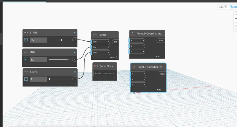
9. In order to make a sinusoidal point to the curve we need MATH.SIN and a RANGER
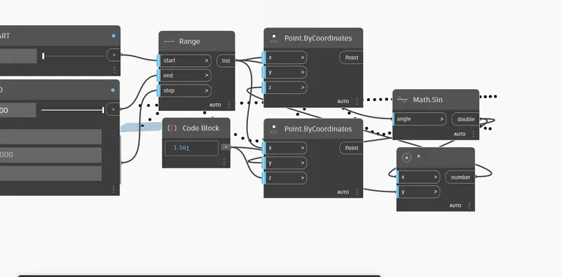
10. Now you just connect the RANGER BOX to the coordinate box. So that the point is visible
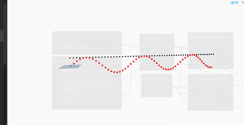
11. Now we need to make the PRODUCT
12. After connecting the Nods to their respective inputs. Now you have to make the sinusoidal curve
13. In order to make the sinusoidal curve we need to input the nubs-by-curve option, similarly, we need to insert the list option
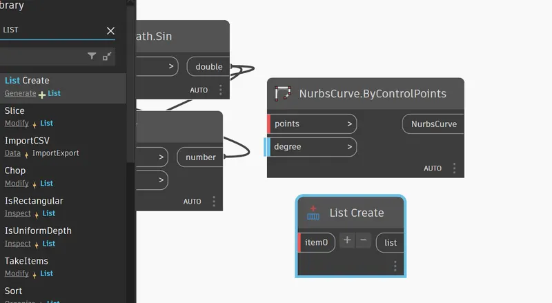
14. Now we have made the curve. Now we have to create a surface by loft
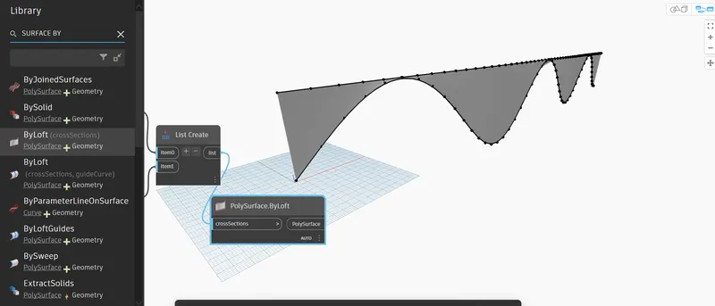
15. Hence the sinusoidal curve is ready
RESULT:
2) Create a conceptual layout of the floor plan in dynamo. Using the tools available in dynamo link the lines to appropriate model elements in Revit by choosing the wall types and wall parameters. Make use of the sliders to slide through the height of the wall and the length of the wall.
ANSWER=
AIM: To Create a conceptual layout of the floor plan in dynamo
PROCEDURE:
1. For making a wall we need to choose an integer slider first
2. Insert 2 integer slider
3. Assign the value
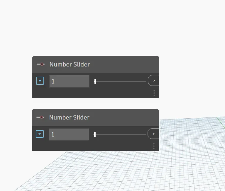
4. For drawing a wall we need to insert point-by-coordinate
5. So the wall has 4 sides we are gonna need 4 point-by-coordinate
6. Now connect the appropriate nods
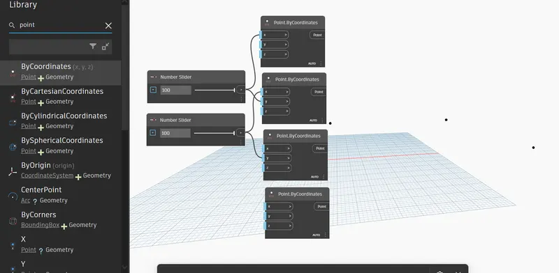
7. So till now we have created 4 points
8. Now we need to make a line through the point. by using line by Startpoint, Endpoint
9. We are gonna need four of them
10. We need to connect the nods of point B.C to the line by S.P, E.P
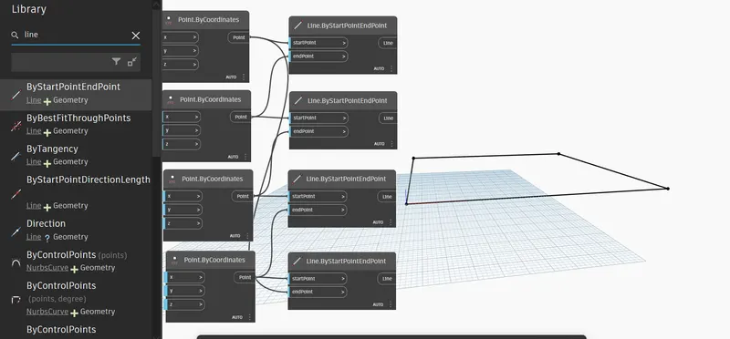
11. In order to make it complete we need to connect the line to the list option
12. Now insert the list and create an option and insert 4 of them
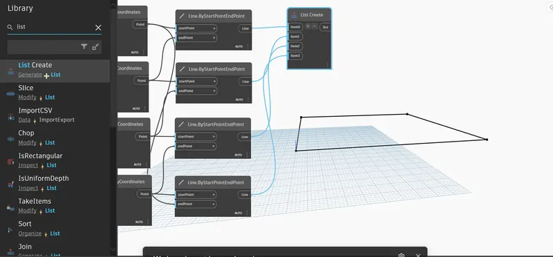
13. Now we need to set the level, wall type, and another integer slider
14. Now opt for the appropriate level, type, and height for the wall
15. After making the setting connect it with Wall by curve and height option
16. Connect the appropriate corresponding
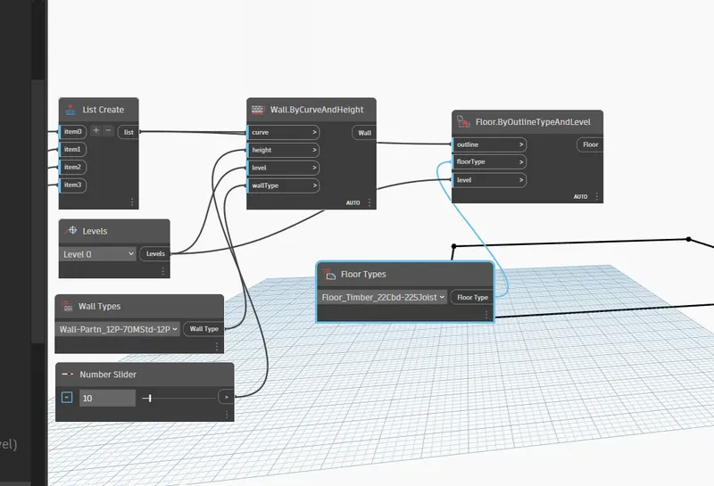
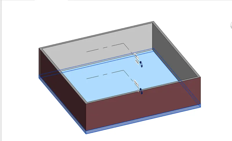
17. Wall will be visible in the Revit interface
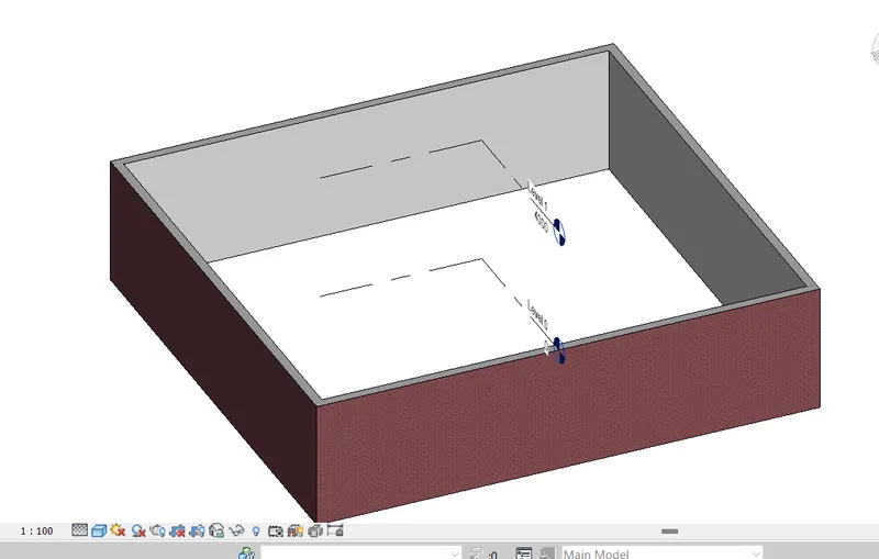
18. So now in order to create the floor using dynamo
19. Go to the dynamo and inset the floor type option and Floor by outline and level option
20. Connect the appropriate corresponding
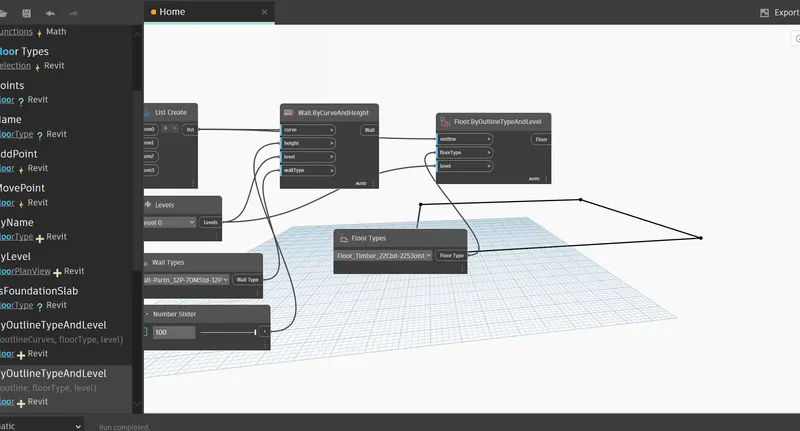
21. Cross-check it in the Revit
22. hence the geometry is ready
RESULT :
3) Create an array of model elements in Revit. Use dynamo to vary the properties of model elements by using the slider or code block
ANSWER=
AIM: To Create an array of model elements in Revit using Dynamo.
PROCEDURE :
1. First create a bunch of elements in the Revit interface
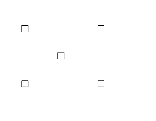
2. Now go into the Dynamo interface
3. First you insert the select model element option
4. And for rotation insert family rotation rotation
5. For Rotation degree use an integer slider
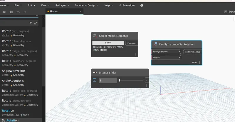
6. Click select in the model element and open the Revit interface and select all the component
7. Then the model will be selected in the dynamo
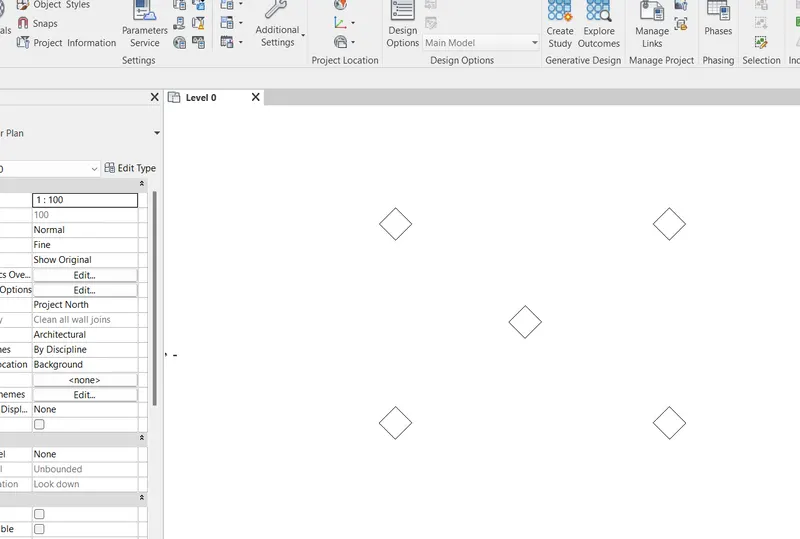
8. Using an integer slider to change the Degree of the element
RESULT:
4) Create a conceptual mass in Revit and develop a parametric column by dividing the surfaces and applying concepts similar to those used in parametric walkway modeling. Use triangular bent or square-shaped panels to add a finish to the parametric column
ANSWER=
AIM: To Create a conceptual mass in Revit and develop a parametric column by dividing the surfaces and applying concepts similar to those used in parametric walkway modeling
PROCEDURE:
1. First we need to create a conceptual mass
2. Just click on the new You will get an option of conceptual mass
3. Now go to the conceptual mass option you will find a matric mass option click on it and open it
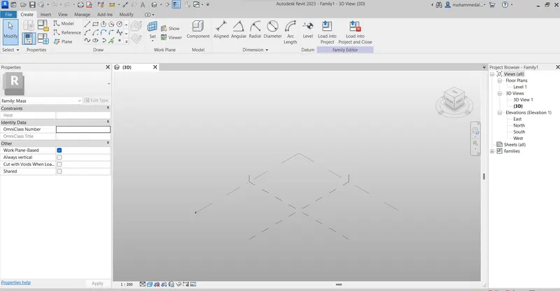
4. Now create a level of 4m
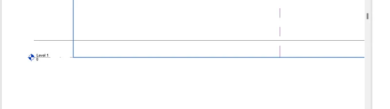
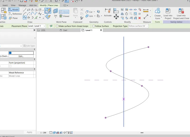
5. Go to in create option and click on the model line on the choose spline option
6. Create a spline curve
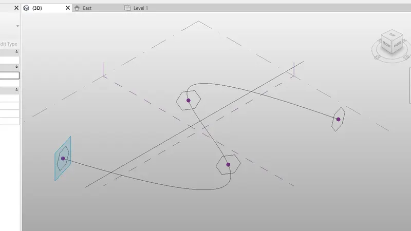
7. Now set the plane with the help of the set option
8. After setting the plane choose the circumscribed option to create a polygon
9. Now create polygon on the visible point
10. Now go to the Create tab click on the curve drop down the create form and then select a solid form
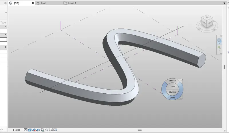
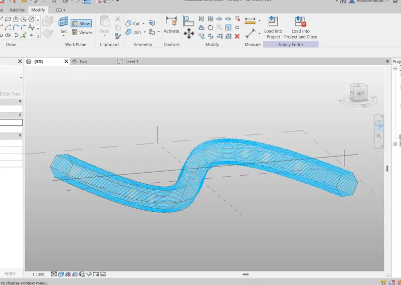
11. In order to make a triangle bent, click on divide surface, Choose the property form then the property browser, then select the triangle bent
RESULT :
5) Use Dynamo to work on developing a Parametric Stadium. List your parameters and use the visual programming approach to complete the modeling, You can use the concepts discussed in the parametric high-rise tower in class for reference.
ANSWER=
AIM: To Use Dynamo to work on developing a Parametric Stadium.
PROCEDURE:
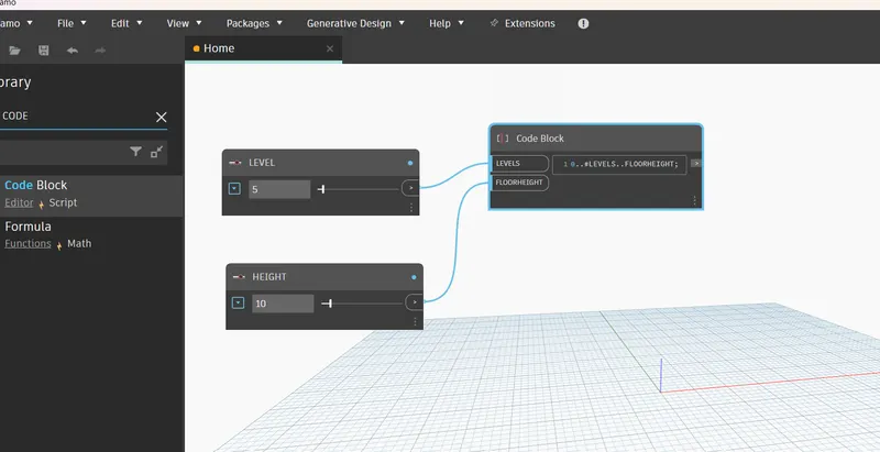
1. First in order to create a parametric building we need to define the number of levels and the floor heights
2. we are gonna need to an integer slider one is for level and another is for floor height
3. Now you have to assign the code block and provide code in it
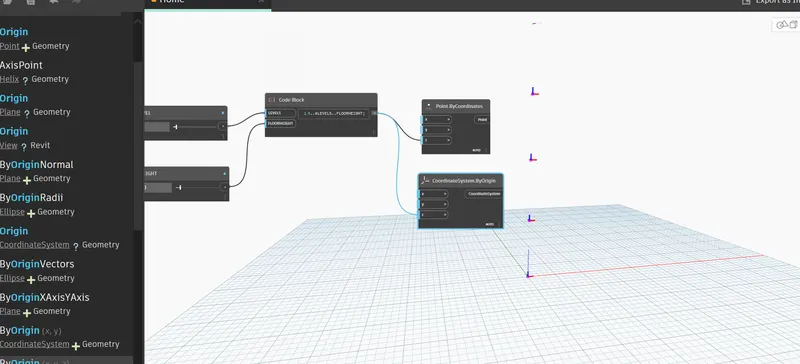
4. Now insert the point by the coordinate system and the origin system by coordinate
5. Now connect the Code block to z, when you connect point will be visible
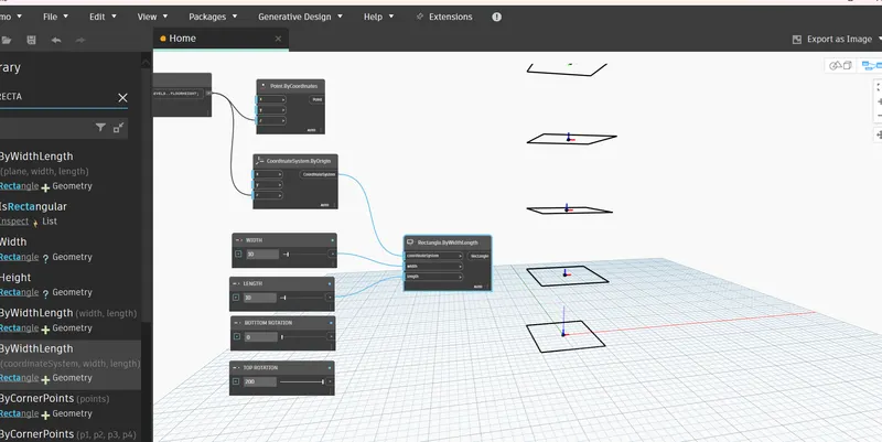
6. Now we need to assign the width, length, and flow rotation to the building
7. Just insert the integer slide (4 nos)
8. one for width, one for length, one for bottom rotation, and one for top rotation
9. Rename as per their function
10. Now we need to connect the width and length to the rectangle option
11. insert the rectangle by width and length
12. connect the respective corresponding
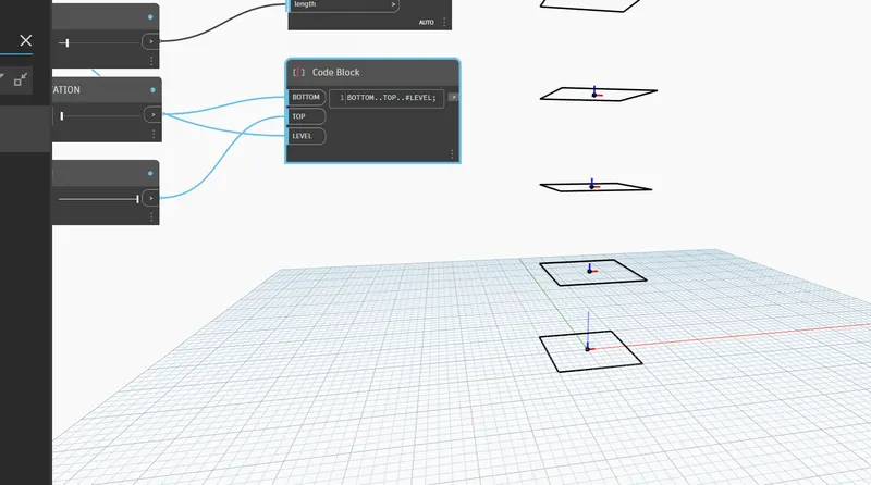
13. Now we need to connect one more code block to connect the floor rotation
14. Code for floor rotation ( bottom..top..#level)
15. Connect the respective coordinate
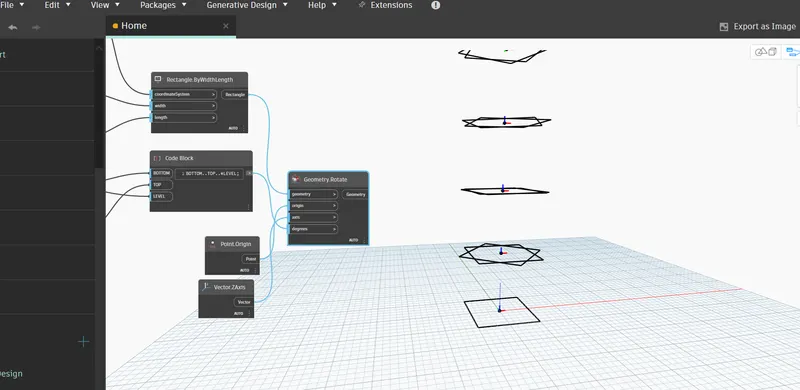
14. Now we need to connect the code block to the geometry rotation
15. Before that we just have to create a point origin and vector.z-axis
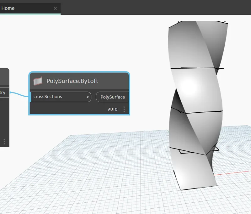
16. Now we need to assign the surface to the parametric station using a poly surface by loft
RESULT :