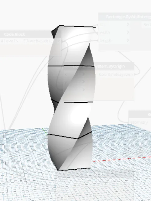
Creating Conceptual mass in REVIT and Creation of Sinusoidal curve and a Parametric stadium using Dynamo
1) Using Dynamo create a set of sinusoidal points and create a curve and create a surface out of the curve.
Aim: Using Dynamo create a set of sinusoidal points and create a curve and create a surface out of the curve.
procedure:
In manage, tab selects the dynamo.
Then dynamo window opens and new option.
now, start the process with three integer sliders.
this can be done by typing code block
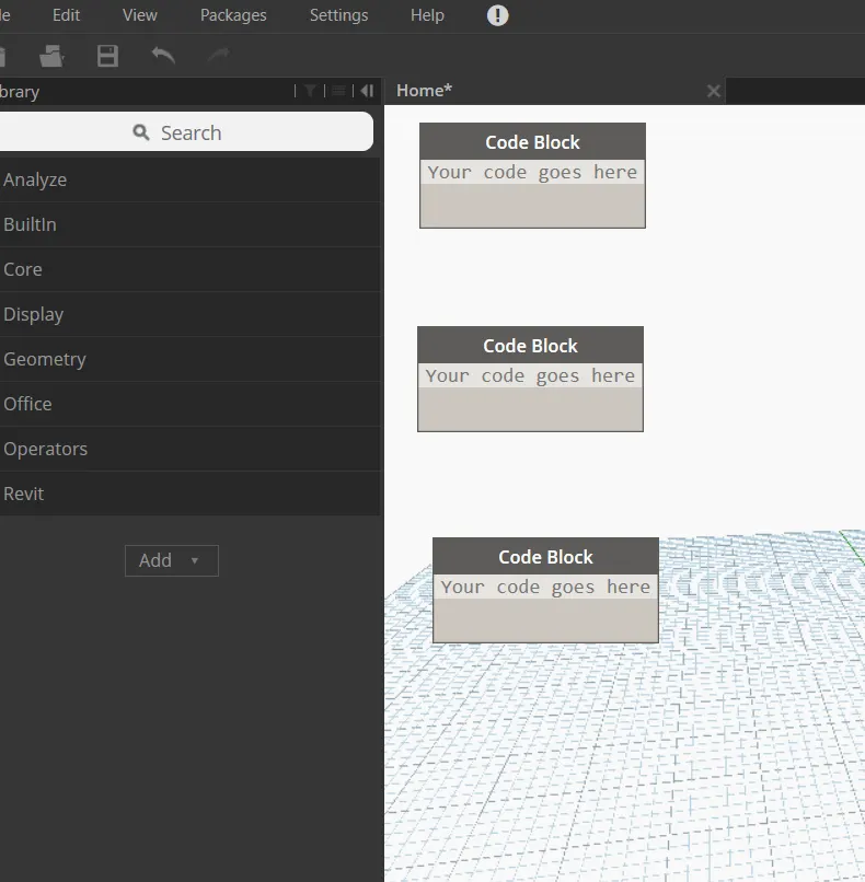
one block is named start ( value-5)
second one end ( value-500)
third one step ( value-2)
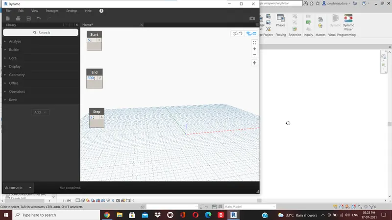
type range in the search panel of the library and insert it.
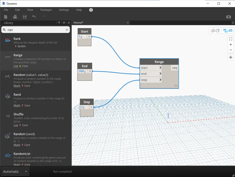
we have to produce sin wave out of these points .
we have to insert sin function
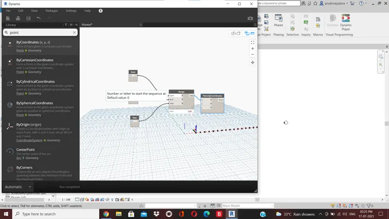
sin values are very small so, we need to amplify it
it inserts another integer slider
name it as an amplifier.
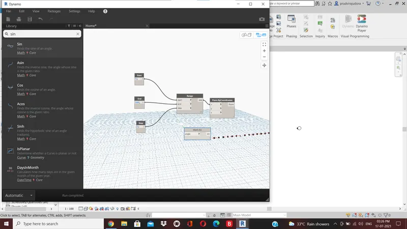
next we have to provide phase for the sin curve
insert an integer slider and name it as phase.
now the phase block is then added to the amplified sin block()
add operator block from library
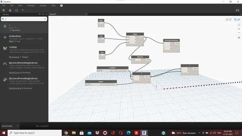
sinusoidal curve is also developed
next step is to develop surface
firse create a group of these items for easy manipulation
entire thing will be grouped together.
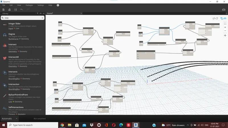
step is to create the surface
first create a list
create in the search panel of library
the sine curves as input for the list
this will serve as the input for surface by loft block
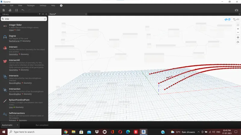
we have to create the surface
search surface by loft
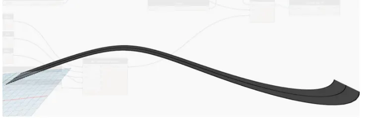
2) Create a conceptual layout of floor plan in dynamo . Using the tools available in dynamo link the lines to appropriate model elements in Revit by choosing the wall types and wall parameters. Make use of the sliders to slide through the height of the wall and length of the wall.
Aim: Create a conceptual layout of floor plan in dynamo . Using the tools available in dynamo link the lines to appropriate model elements in Revit by choosing the wall types and wall parameters. Make use of the sliders to slide through the height of the wall and length of the wall.
procedure:
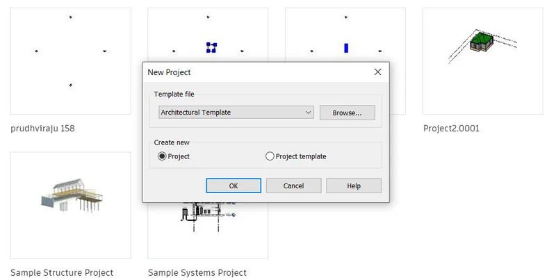
open a new architectural template.
go to the manage tab and open the dynamo
search points by coordinates in the search panel of the library
1st one is named as origin(0,0,0) and the rest is named as control point1(x,0,0) control point2(0,y,0) and control point 3(x,y,0)
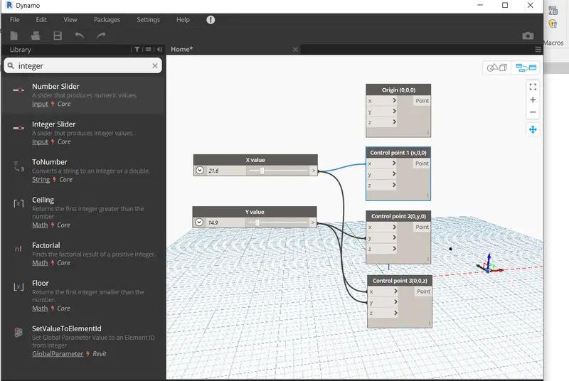
now two insteger sliders to provide the values for x and y values
connect these poines by a line
search line by start and end point and insert 4 blocks
input for these blocks are the points created previosly.
layout of the floor pian is obtained.
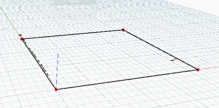
curve combine all the four lines in a list by choosing list create
height another number slider is chosen and name it as height
level search level in the search panel it will contain the levels availbale in your revit folder then choose the level in which you want to place your structure.
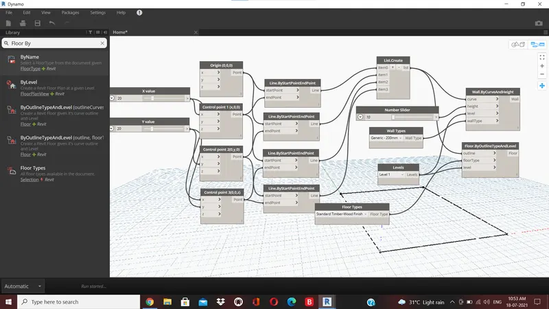
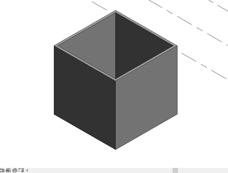
view the 3d form where the height of the wall is visible
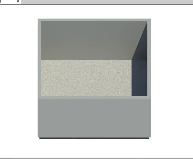
3) Create an array of model elements in Revit. Use dynamo to vary the properties of model elements by using the slider or code block
Aim:Create an array of model elements in Revit. Use dynamo to vary the properties of model elements by using the slider or code block
procedure:
Open a new architectural template in revit file
go to architectural tab and go to columnsand size of the 610mm*610mm
20 columns are created.
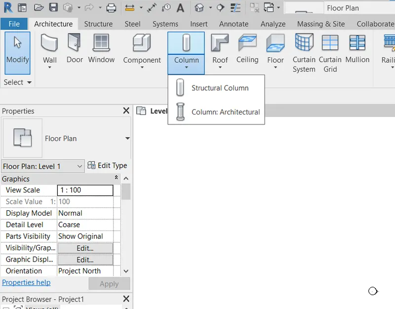
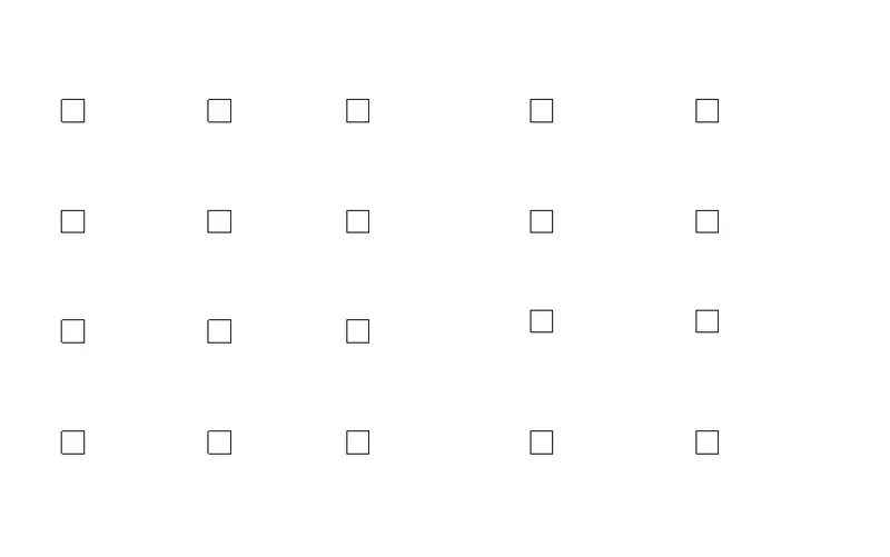
the properties of the model element are varied using dynamo
open dynamo
search panel of the library select model elements integer slider and set rotation.
integer slider is renamed as rotation angle
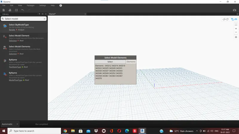
select model elements block will be the input for family instance and integar slider will be input for degree.
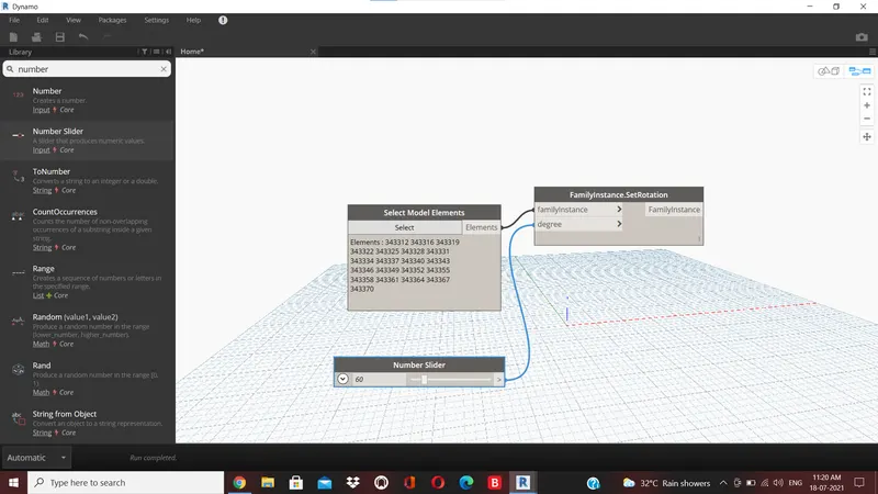

the rotation angle can be varied to desired value.
4) Create a conceptual mass in Revit and develop a parametric column by dividing the surfaces and apply the concepts similar to used in parametric walkway modelling. Use triangular bent or square shaped panels to add finish to the parametric column
Aim: Create a conceptual mass in Revit and develop a parametric column by dividing the surfaces and apply the concepts similar to used in parametric walkway modelling. Use triangular bent or square shaped panels to add finish to the parametric column
procedure:
Open revit software and under the families open a new
now go to elevation view and create a level at 10 feet and name it as height of roof
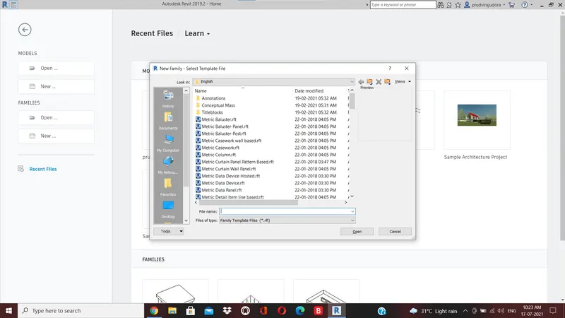
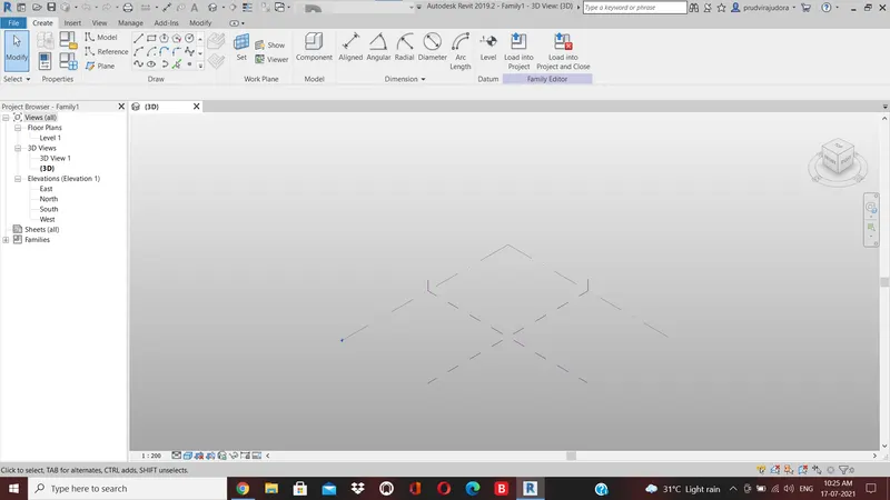
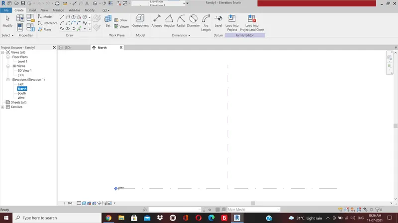
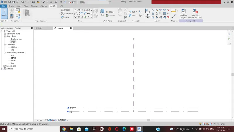
now using spline tool draw the desired outline for the walkway
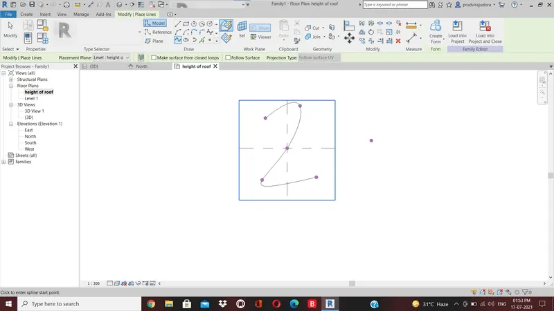
now we have to create a profile to sweep through the curve
for this we have to set the workplace at the points and develop a polygon at the workplace
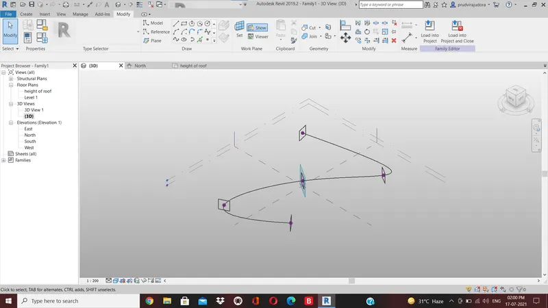
a polygon is developed with point as center
we have to create the surface which done through sweep
select all the polygons and the curve line and choose create form option.
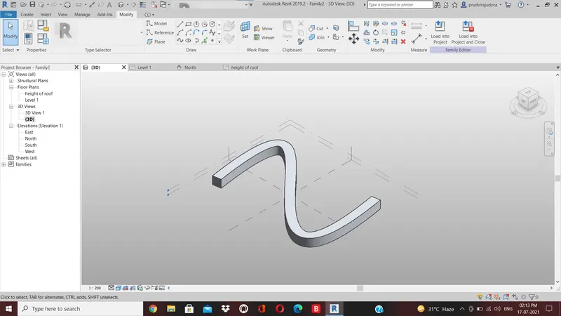
now select the form divide surface then provide the pattern
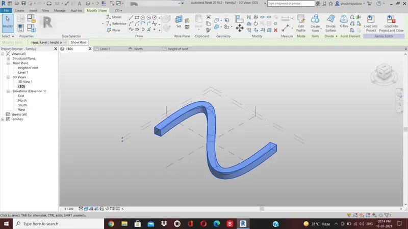
now open a new family curtain panel pattern based
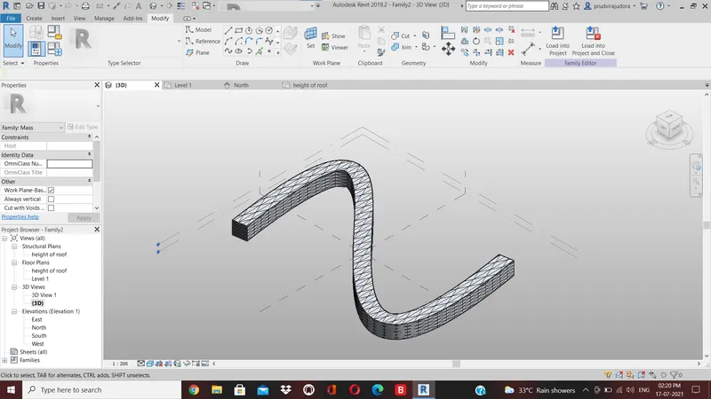
now select the pattern as triangle bent
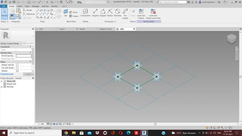
now load this into the project
select the enitre form of the walkway and filter it to retain only the divided surface
then in the pattern select the family that we have created just now
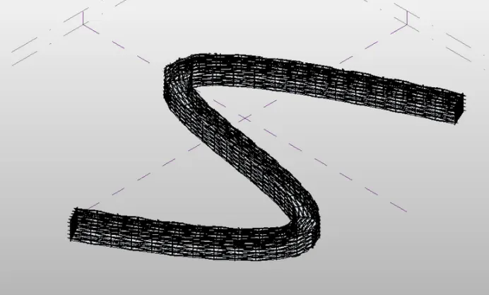
5) Use Dynamo to work on developing a Parametric Stadium. List your parameters and use the visual programming approach to complete the modelling, You can use the concepts discussed in parametric high rise tower in class for reference
AIM: Use Dynamo to work on developing a Parametric Stadium. List your parameters and use the visual programming approach to complete the modelling, You can use the concepts discussed in parametric high rise tower in class for reference
Procedure
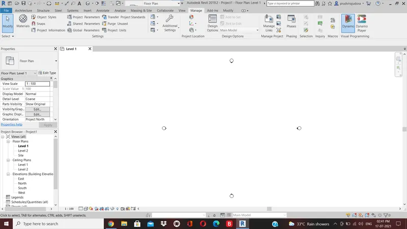
initially open a new architectural template in revit and then open dynamo.
basic parameters to design a high rise structure is created as input in dynamo
number of levels
floor to floor height
bottom floor rotation
top floor rotation
insert a code block from the library to combine level an d floor to floor height and type 0..# level..floorheigth.
connect the integer sliders named as levels and floor to floor hegiht as input to the code block
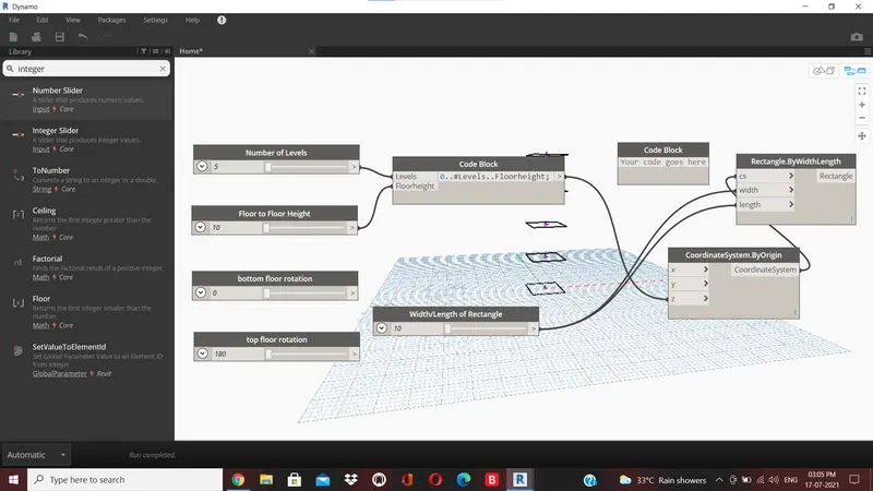
now search coordinates by origin in the library and insert it
then connent the code block as input for z coordinate in the coordinate by origin block
insert rectangle by width and length from the library
inputs requied are coordinate system length and width
connect the input for the rectangle block.
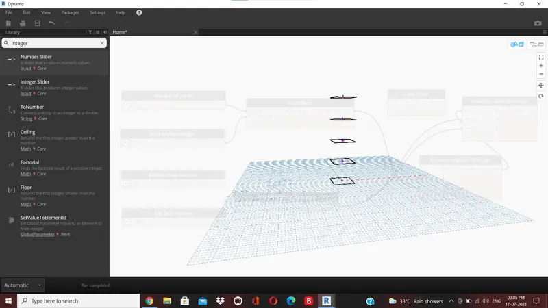
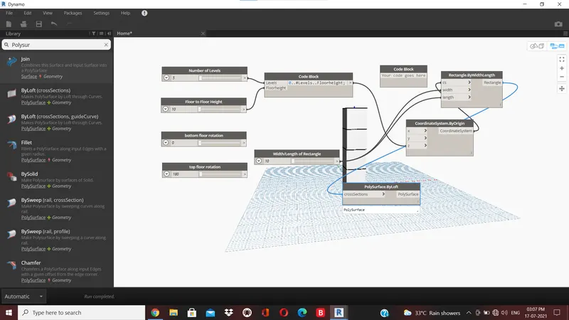
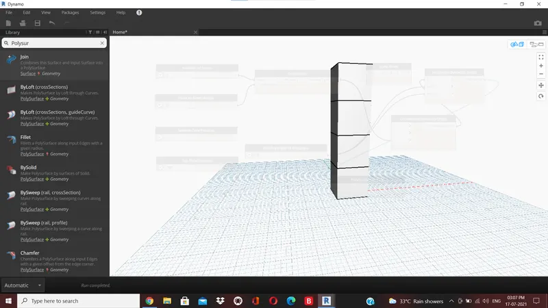
geometry rectangle block
origin insert on origin block from the library
axis:insert vectorZ axis from the library
degrees : for this insert a code block and type bottom..top..#level.
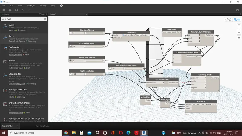
now we have to create surface for this type surface by loft in library
then connent geometry rotate block as input for surface by loft
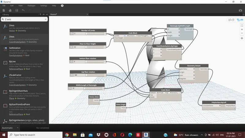
the number of levels and width and length of the rectangle can varied accordingly.