Creating Conceptual mass in REVIT and Creation of Sinusoidal curve and a Parametric stadium using Dynamo
1.Aim: To create sinusodal curve by using dynamo .
software that i used dynamo integrated to revit.
procedure
first open the revit file .
go to manage tab.
click the dynamo in the visual programming panel.
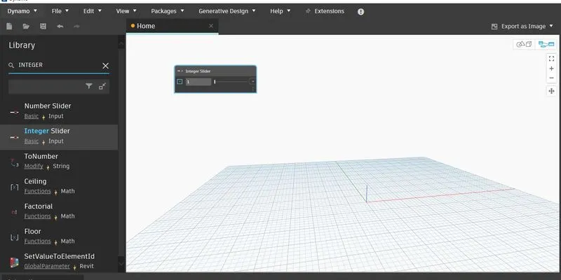
now we can see the interface of the dynamo .
click the new workspace.
go to library type the integer slider.
select that node and name it as first point.
give the minimum value is 10 and maximum value is 50.
set the present as 10.
copy that node and paste it in to convas.
set the name to that node as end point.
take the code block (or) double click on the convas.
set the script as a,b,a+b/2 it shows the input a and b.
wire the start point output port as input to the' a '.
wire the end point output port to inputport of b.
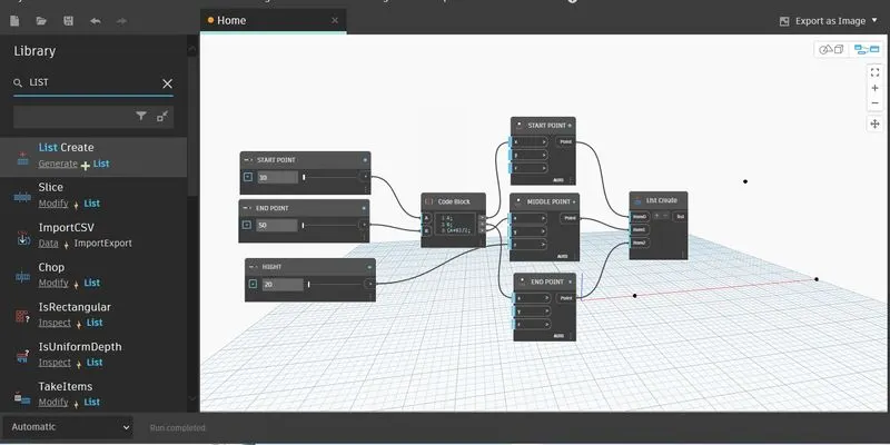
invoke the point by coordinate.
copy and paste in to two times.
set the name as orgin point,centrepoint,endpoint.
wire the a output port to the orginpoint x -axis inputport.
wire the outputport of b to the end point x-axis input port.
wire the a=b/2 output port to middle point x-axis input port.
take integer slider and name it as height set the minimum value 10 and maximum value as 50.
wire the output port of height to the middlepoint z-axis input port.
invoke the list create node .
wire all output port of coordinate to the list node.
invoke the nurb curve by points.
wire the list node output port to the curve input port of nurb curve.
take another code block.
script as phase+math,sin(amplitude*angle).
it shows three input
1.phase
2.amplitude
3.angle.
invoke plane at parameter.
it asks the
curve
parameter as input port
wire the nurbcurve output port to the curve inputport of set plane.
create code block.
script as 0..1..0.01
invoke circle draw circle on the plane.
wire out put to the parameter input port.
take three integer slider set the name as
phase-minimum-1 and maximum -5.
amplitude- 100-2000,
wire output of the amplitude and phase slider to the amplitude and phase input port.
invoke the maprange it asks three input.
1.numbers.
2.minimum
3,maximum.
wire the 0..1..0.01 output to the number input.
create code block and give the values 0.01and 1.
wire the this output to the minimum and maximun outputports.
wire the range node output to the angle input port .
now we can see the sinosodial curve.
add surface to it.
by invoking loft cross section.
now by changing the parameters we can see change in the model.
until you statisfy change the parameter that we assign .
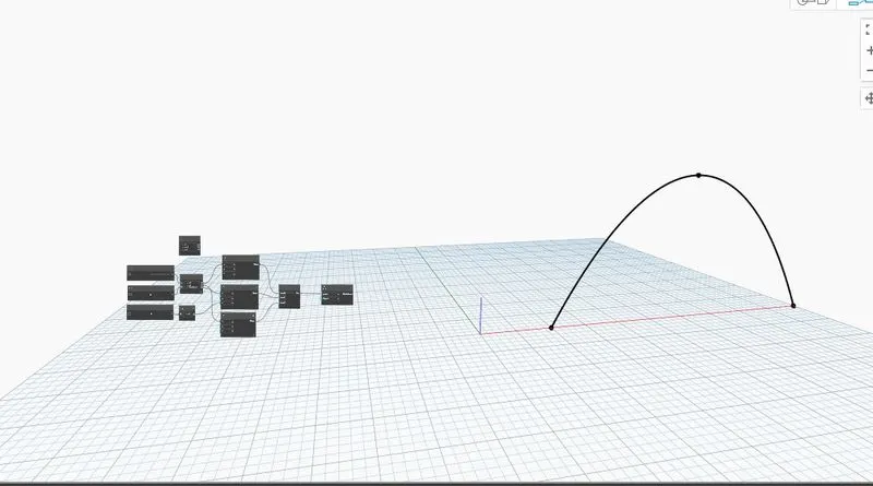
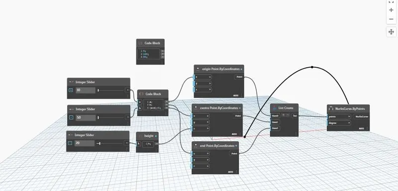
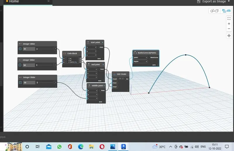
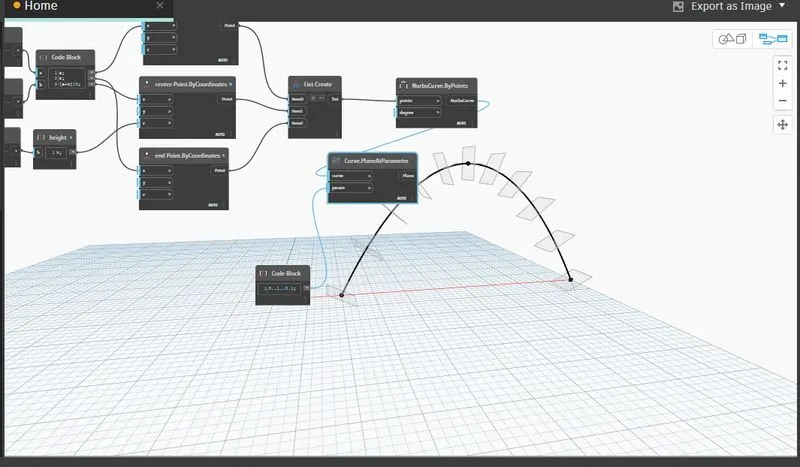
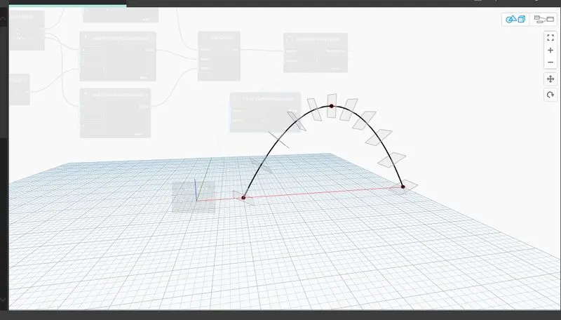
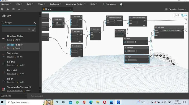
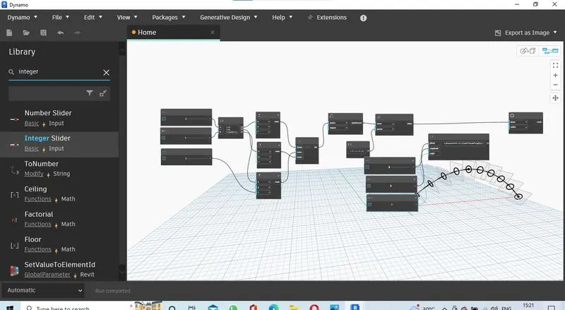
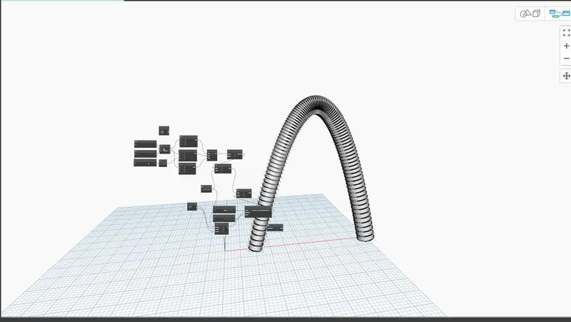
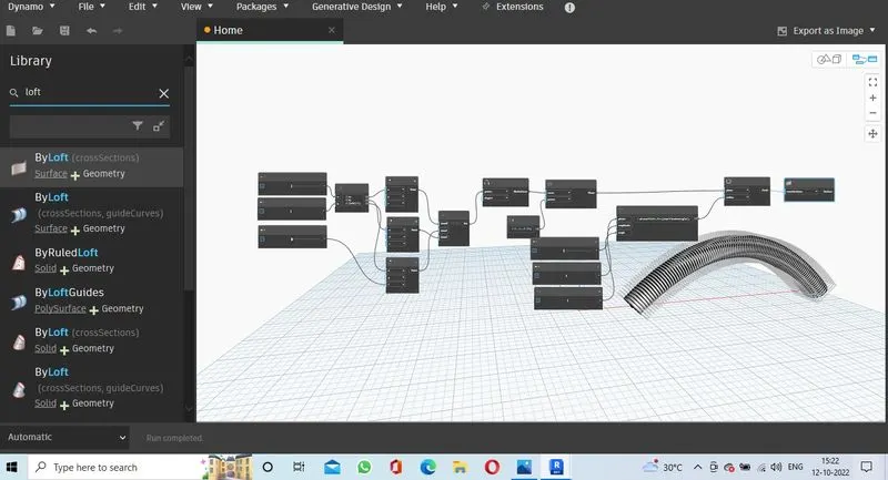
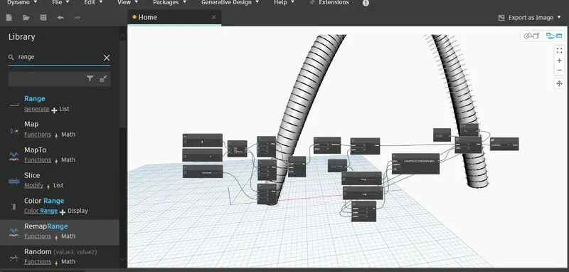
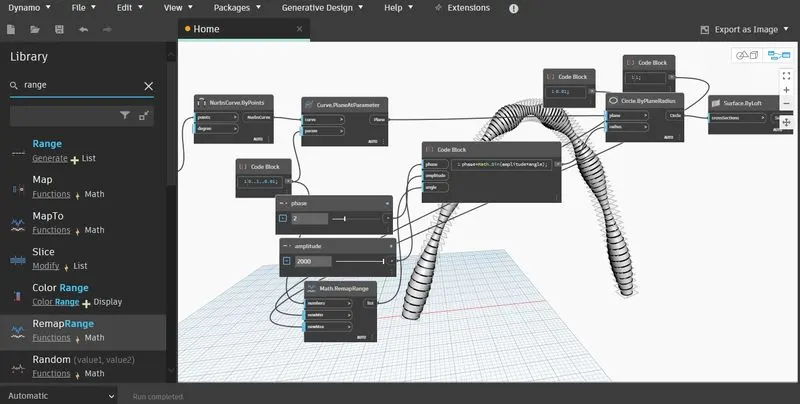
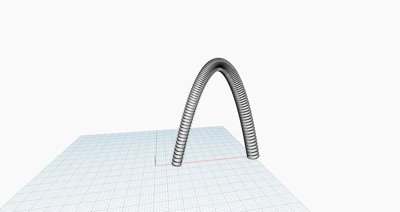
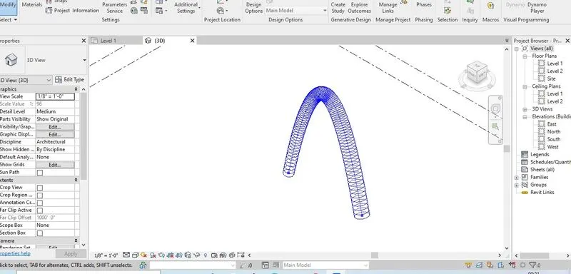
Result: I have created the sinusoidal curve with surface in dynamo.
2.Aim: To create a layout of floor plan and add wall to it using dyanmo integregated to rivet.
procedure
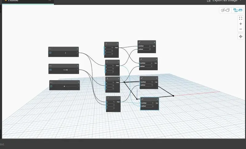
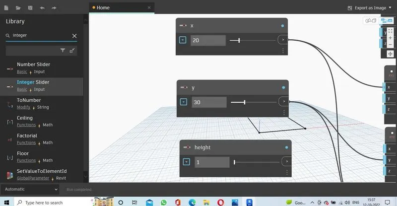
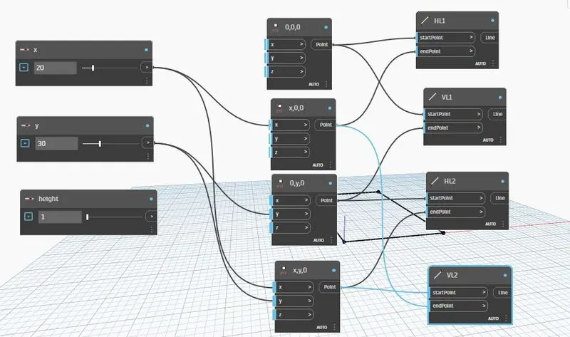
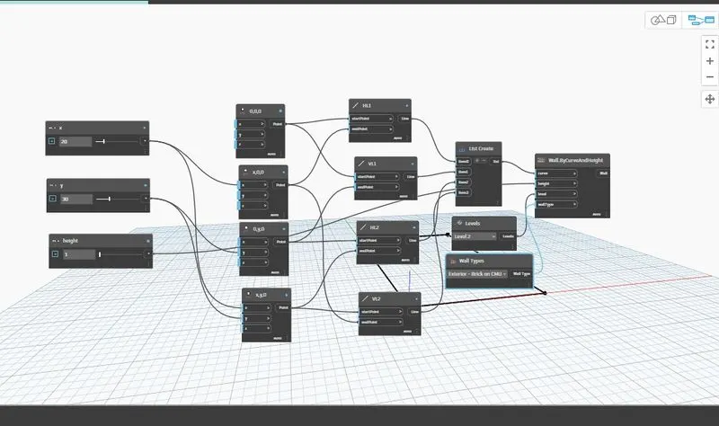
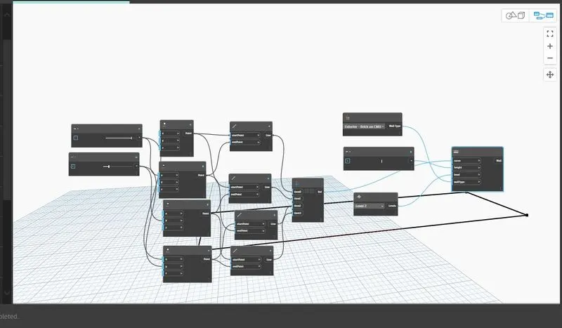
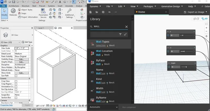
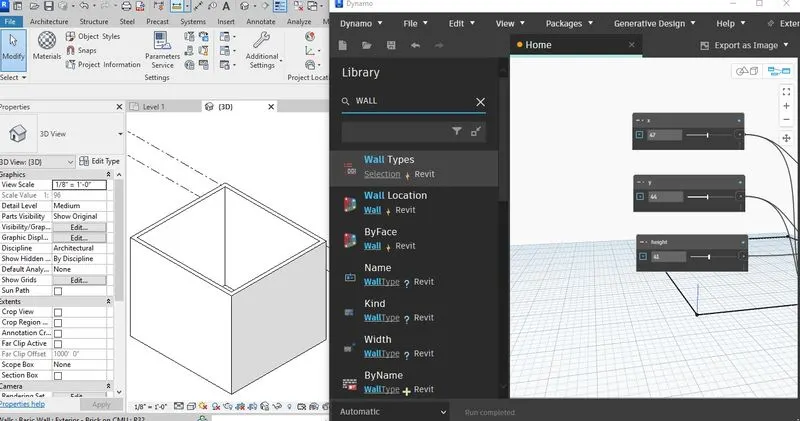
Take three integer slider nodes set the name as x,y and height.
invoke point by coordinates nodes copy and paste it in three times.
set the names as (0,0,0),(x, 0,0),(0,y,0),(x,y,0).
wire the x node outputport to the (x, 0,0) x-axis inputport.
wire the y-node output port to the (0,y,0) y-axis inputport,
wire the x and y node output to the (x,y,0) x and yaxis inputport.
invoke the line by points node.
copy and paste in to three times.
and name it as hl1,vl1,hl2,vl2.
the line node aks the start point and end point input.
hl1 line
wire the (0,0,0) as input to the start point.
wire the (x, 0,0) as input to the end point.
vl1
wire the (0,0,0) as input to the start point.
wire the (0,y,0) as input to the end point.
hl2
wire the (0,y,0) as input to the start point.
wire the (x,y,0) as input to the end point.
vl2
wire the (x, 0,0) as input to the start point.
wire the (x,y,0) as input to the end point.
invoke the list create node.
it take the all out put of the lines as a input with the wire.
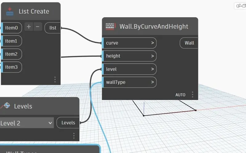
invoke the wall create.
it asks the input
1.curve
2.height
3.wall type.
4.level.
for the curve input wire the output of the list.
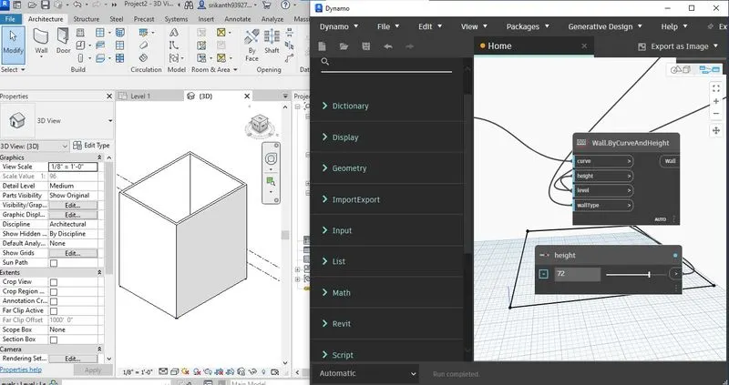
wire the height slider to the height input port.
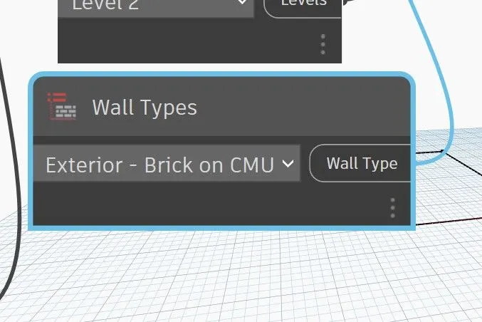
invoke the wall type and levels.
select the wall type as brick on cmu.
set the level as level as 1.
wire the walltype and level output to the wall type and level input port .
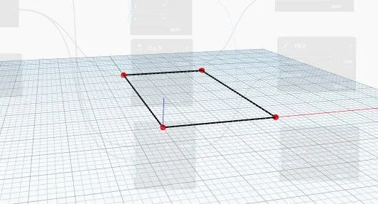
now open the revit file you can see the wall.
this is how dynamo integrated to the revit.
now change the parameters affect the model.
according to the changes the model has changed.
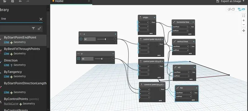
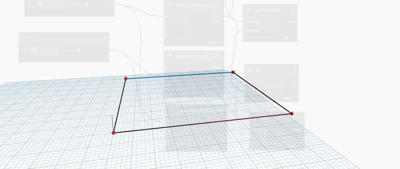
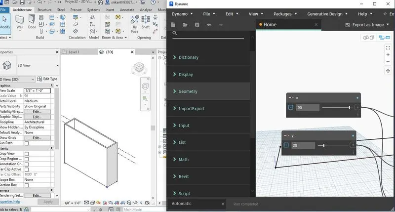
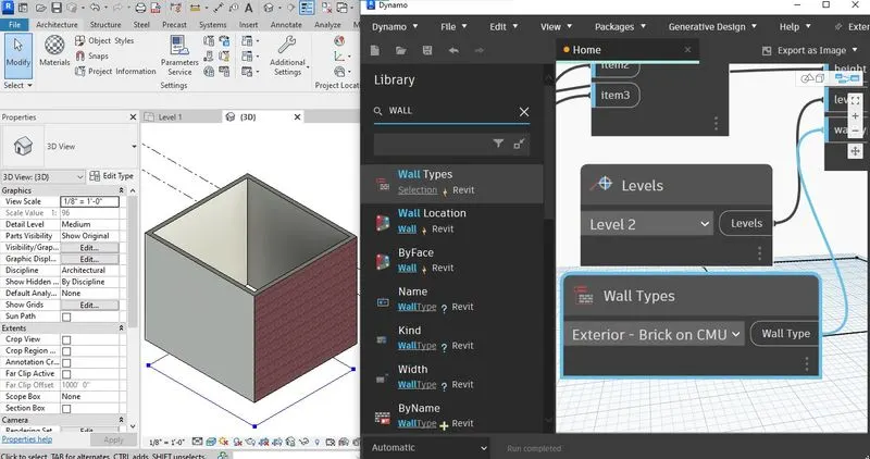
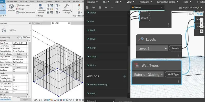
Result: I have created a layout of floor plan and added wall to it using dyanmo integregated to rivet.
3.Aim : To change the parameters of the elements in the rivet by using dynamo.
procedure
create a model element in the rivet like column.
use array tool and distribute in transverse and longitudinal.
now open the dynamo .
invoke the integer slider,code block,set rotation,select of model elements,levels nodes.
set the integeter node name as rotation value.
set the minimum as 1and maximum as 360.
set the level as 2.
in thye set rotation node it asks input
1.familyinstance
2.degree.
click the select in the select model elements node.
go to revit select elements.
now shows in the nodes .
wire the select model node output port to family instance input port.
wire the rotation value output port to degree input port.
now the slide the value we can see the change in the model according to change in the parameter in the dynamo it changes.
we can change the levels.

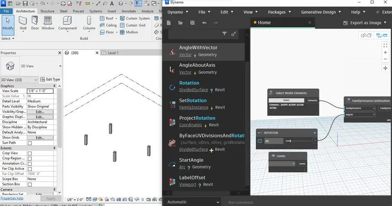
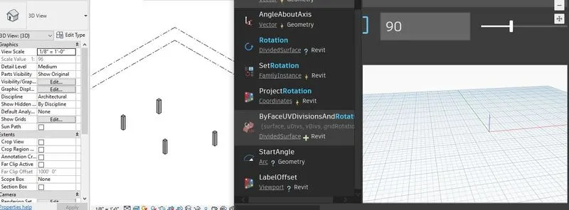
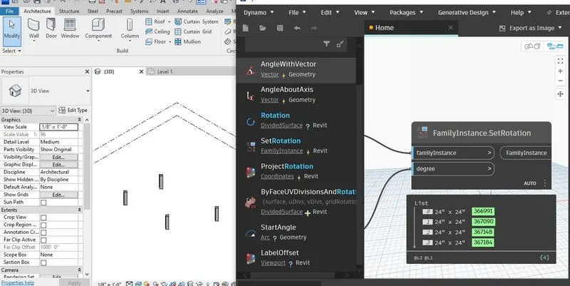
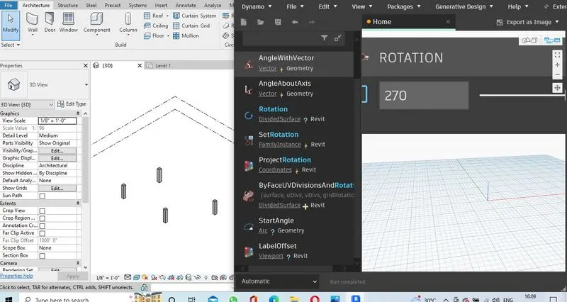
Result: i have change the parameters of the elements in the rivet by using dynamo.
4.AIM: To create the conceptual mass of paramaetric column.
procedure
open the rivet file.
go to file tab
select te family new .
select the conceptual mass template.
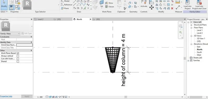
go the noth view set the another level at 4m.
take reference point place at the centre at the both two levels.
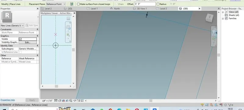
set the work plane paralllel to the levels.
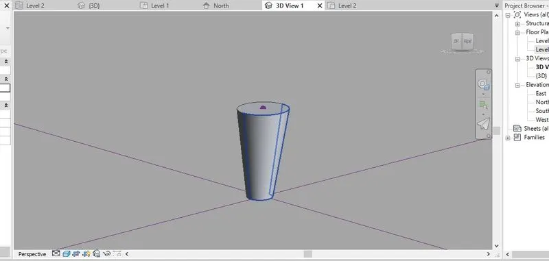
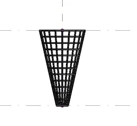
take circle tool draw the circle at bottom with 0.6m radius.
draw the circle at top with 1.2 m radius.
in the ribbon we can see the to form option.
select the objects which i have drawn and select that option.
now it make in to solid.
select the tool like divide surface in the ribbon.
select the face and assign it.
before go to property panel select the triangular pattern.
it does not suit well to my model.
so that i create another pattern by taking generic model bsed on pattern template.
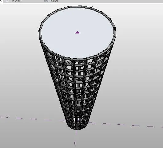
i created the polygon shaped surface pattern.
load in to the project.
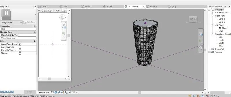
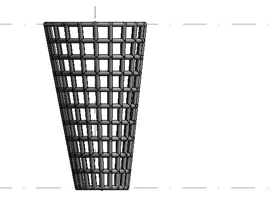
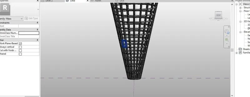
assigned the pattern to my column surface.
now i made the parametric column.
go to annotation select the aligned dimension.
select the points .
select the dimension go to label option assign the parameters to my model.
save the file in to my computer.
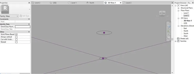
Result: I have created the conceptual mass of paramaetric column.
5.Aim: To develop the parametric stadium using dynamo.
Software that i used : dynamo integreated rivet.
procedure
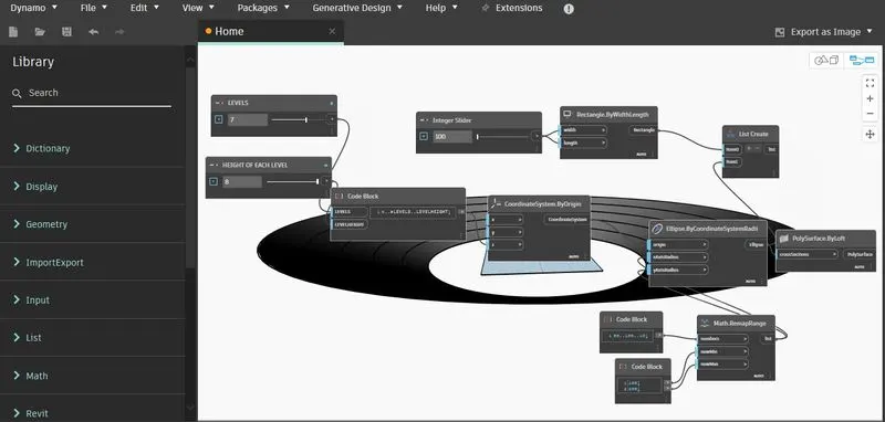
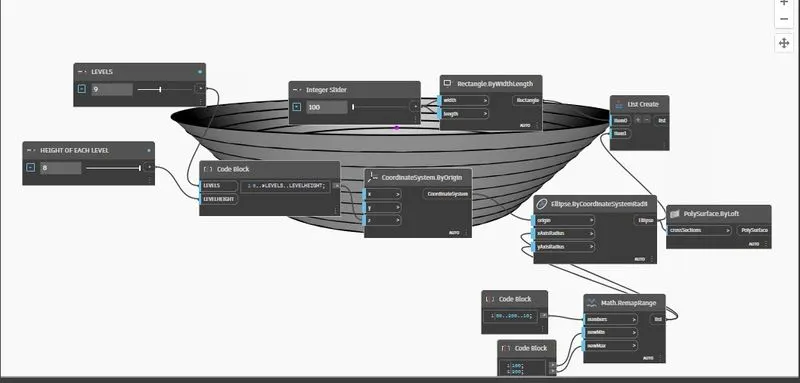
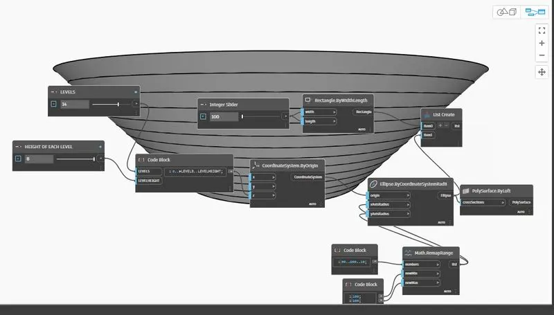
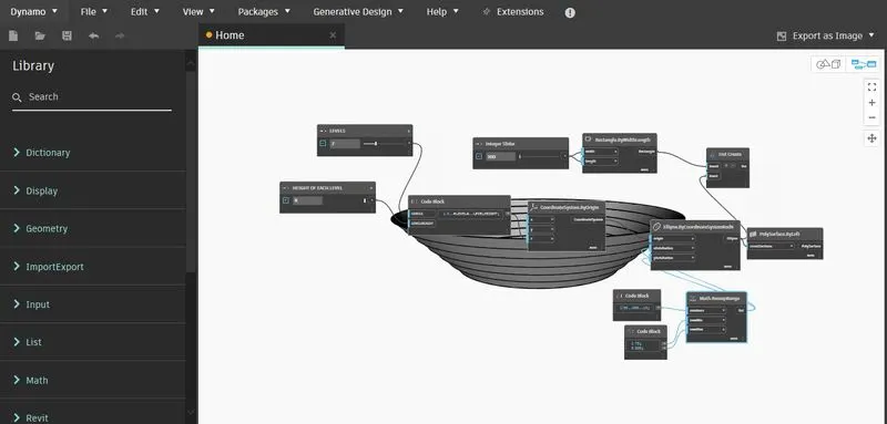
In this project i have created the parametric high rise building and parametric stadium.
create rivet file .
go to manage tab .
select dynamo.
another window will open.
we can see the interface of the dymano.
create new create workspace .
go to library.
type the integer slider node.
it will display on the convas.
copy the node and paste it on the convas.
set the the interger slider name as levels and height of each level.
take code block.
and script as 0..#levels..levelheight
it wii shows two input
1.levels
2.level height
wire the levels node output port to levels inputport.
wire the height of each floor output port to level height inputport.
invoke the coordination system by origin.
wire the output port of last node to the coordinate y-axis input port.
invoke the rectangle by width and length node.
take integer slide name it as width-length wire it to the rectangle input port.
invoke ellipse by coordination system radii.
it shows three inputs
1.origin
2.x-axis radius.
3.y-axis radius.
take remap range node it shows three inputs
1.numbers
2.minimum number.
3.maximum number.
take two code blocks.
in the first set the phrase-50..100..10
in the second node give values 100
200
wire the first code block output to the number output port of range.
wire the second values to the minimum and maximum input .
wire the coordination system output port to the origin input port of ellipse.
wire the range output to the x and y-axis input.
take loft of poly surface by crossection node.
wire the ellipse output port to the crossection input port of polysurface.
now change the levels parameter and height of each level we can see model has changing.
change the parameter until gets the desired shape.
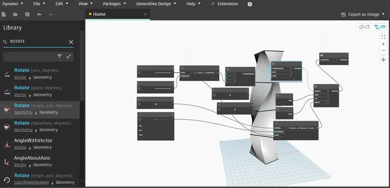
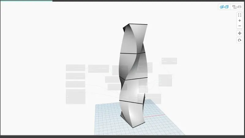
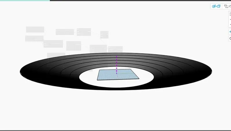
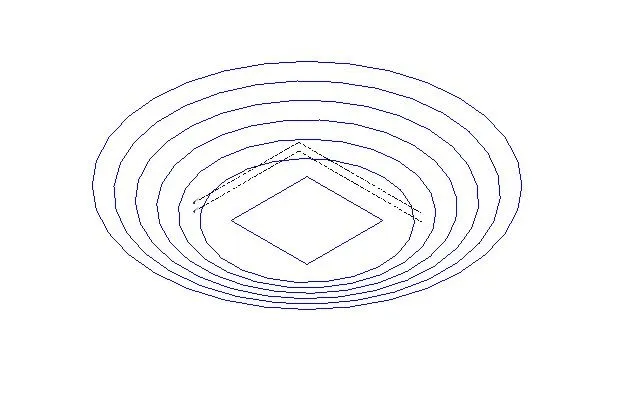
Result: I have developed the parametric stadium by using dynamo.