Creating Conceptual mass in REVIT and Creation of Sinusoidal curve and a Parametric stadium using Dynamo
1) Using Dynamo create a set of sinusoidal points and create a curve and create a surface out of the curve.
Ans 1.
INTRODUCTION: Creating surface from the curve created from sinusoidal points using Dynamo
AIM: To create a set of sinosoidal points and creating curve and as surface out of the curve using Dynamo
PROCEDURE:
- Open a new Revit Project
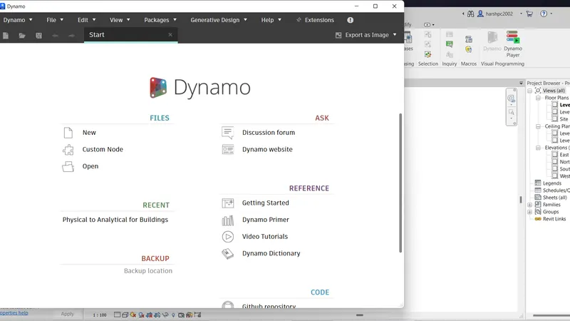
- From manage Tab open the Dynamo project
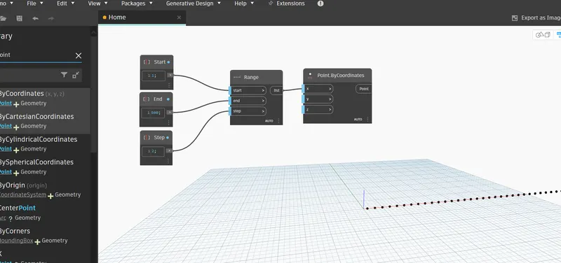
- Provide the range command
- Create Code for Start, End and Step for the Range input
- Create point by Coordinates command and get the input for X coordinate from Range
- The array of points will be created along X axis
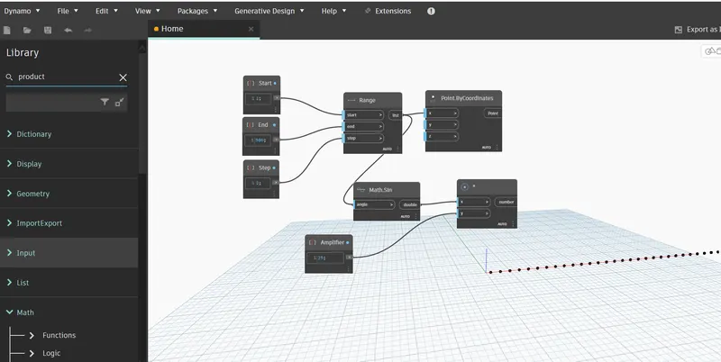
- Create Math Sine command for the sinusoidal curve and provide input from Range
- Create Slider and name it as Amplifier to increase or decrease the curvature of curve
- Create product command and get input from the Amplifier to Y coordinate and input from Math Sin for X coordinate.
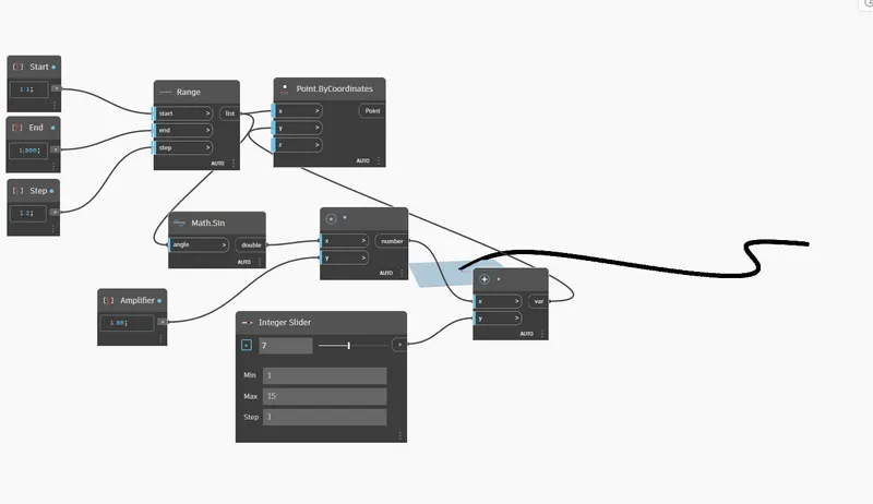
- Provide the Add command for X & Y coordinates and input to X from the product command and create as Integer slider for the input to Y
- Provide the output pof the Sum to Y coordinate of the Point
- The Sinusoidal curve in points will be formed along the X axis with the curves along Y axis
- To create line from the points use the Nurbscurve by control points command
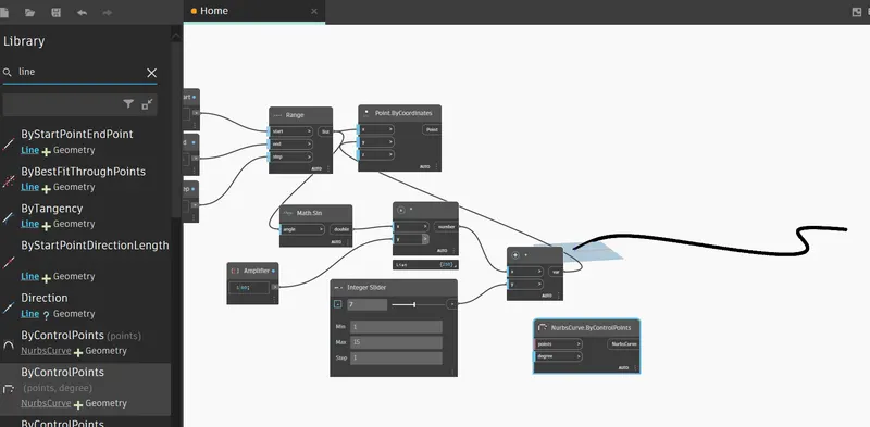
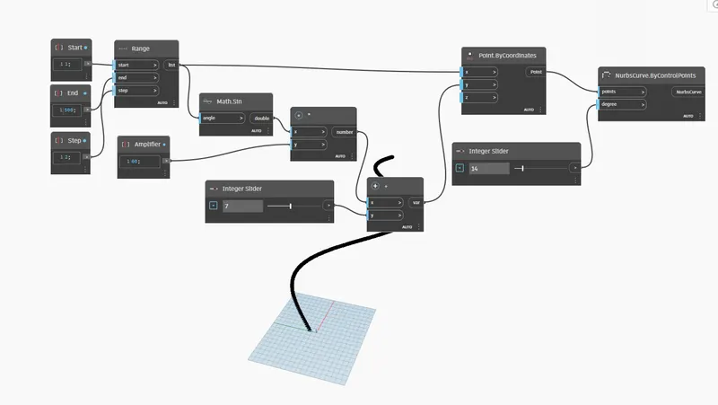
- Provide slider for the Nurbs curve for input to degree and input from the Point for points.
- The line will be created by joining the points
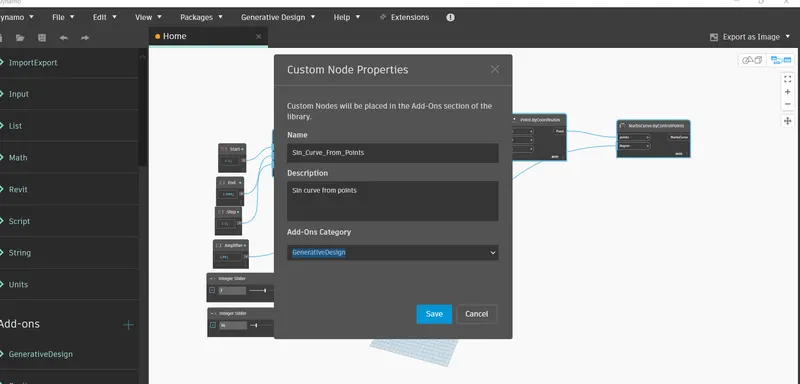
- The nodes can be grouped by creating a name as Sin Curve from Points as shown below from custom node properties
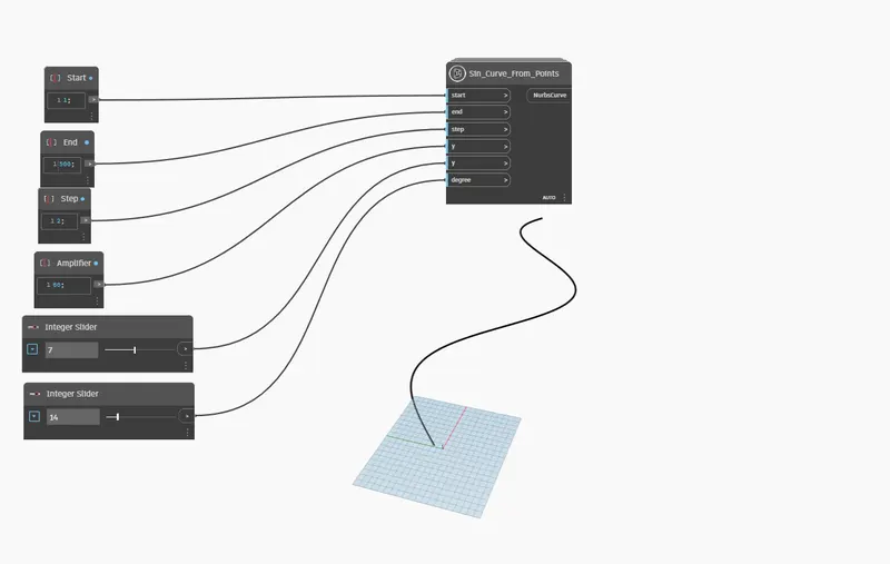
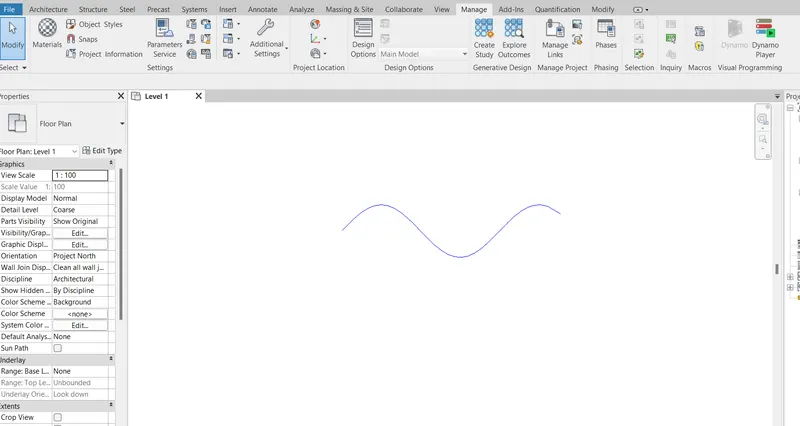
- The curve is also created in the Revit project as seen below
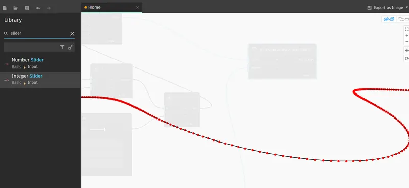
- Line joining the points to form curve is shown below
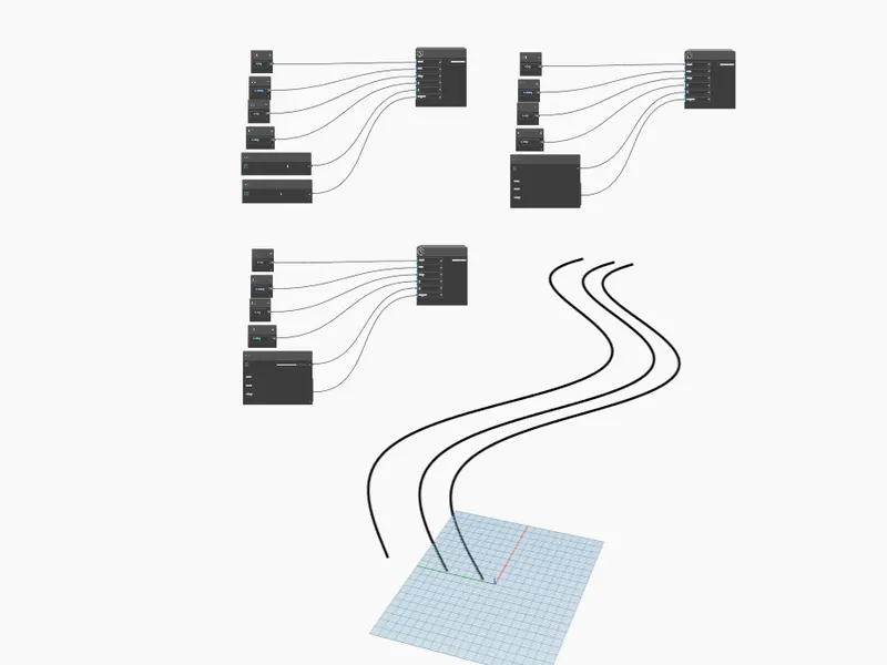
- Copy the node group to create more set of the curves by adjusting the slider or values of X coordinate to separate the curves
- 3 curves are created as shown below
- Create a list of curves with input from the 3 curves
- Create Surface by loft command and input from the List
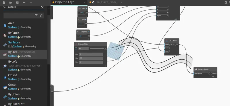
- The surface joining the curves is created as shown below
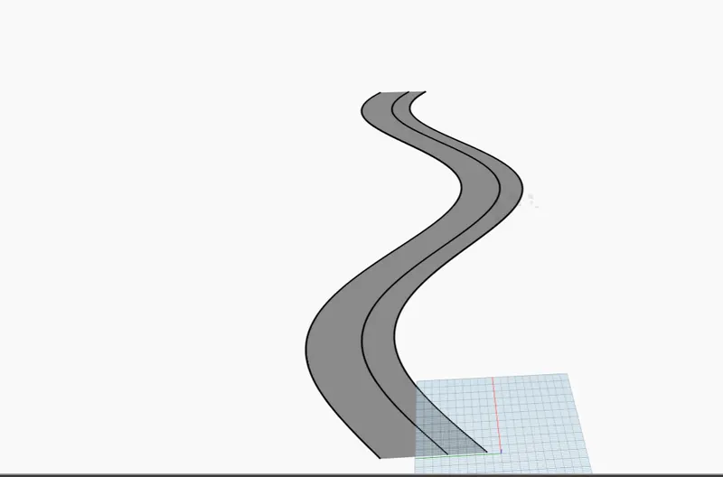
- Same is created in Revit project as shown below
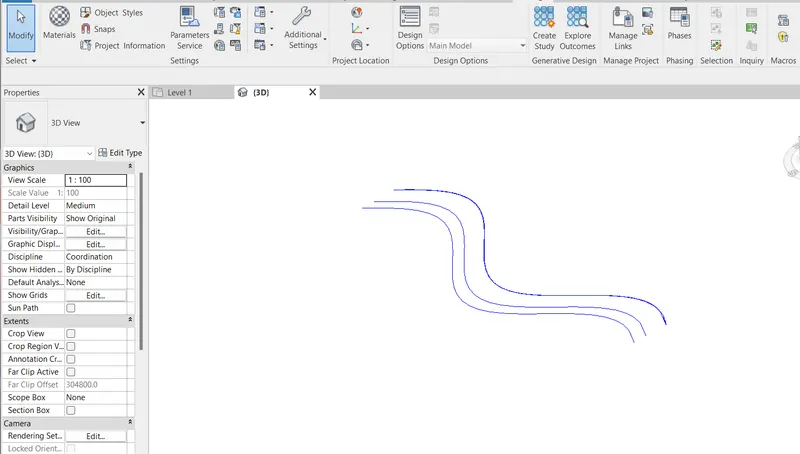
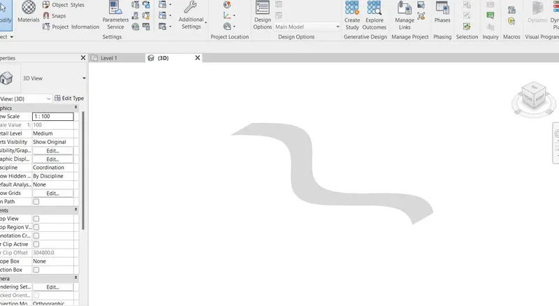
CONCLUSION: Thus we have created a curve from the sinusoidal set of point and then created the surface from the curves using Dynamo.
2) Create a conceptual layout of floor plan in dynamo . Using the tools available in dynamo link the lines to appropriate model elements in Revit by choosing the wall types and wall parameters. Make use of the sliders to slide through the height of the wall and length of the wall.
Ans 2.
INTRODUCTION: Creating conceptual layout of floor plan using Dynamo
AIM: To create a conceptual layout of a floor plan using Dynamo by using appropriate wall type and parameters and providing slider to change the height or length of wall.
PROCEDURE:
- Create 4 Points by coordinates commands for the corners of the room walls.
- Create 2 Integer sliders
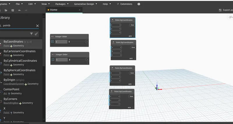
- Provide the slider inputs of coordinates to the Point by coordinates command to create 4 points
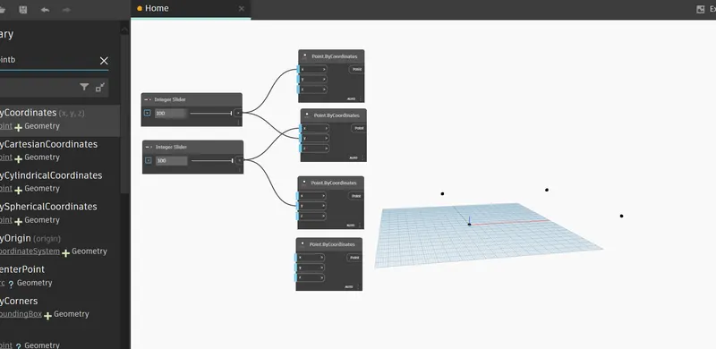
- Create Line by start point end point command for 4 lines
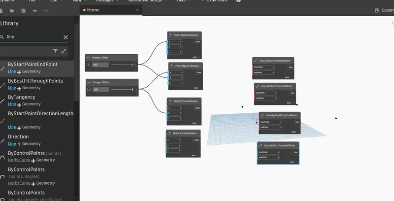
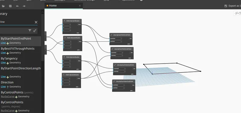
- Provide inputs from the Points by coordinates to the Line commands such that the outer periphery line of the room walls are formed
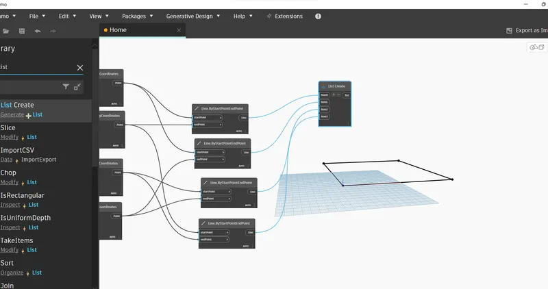
- Create list of the lines.
- Create the Wall by curve and height command for the walls
- Create inputs of Wall type by selecting the required wall type, Levels, and provide slider for the wall height
- Provide input of the Lines from the List command to the Wall command
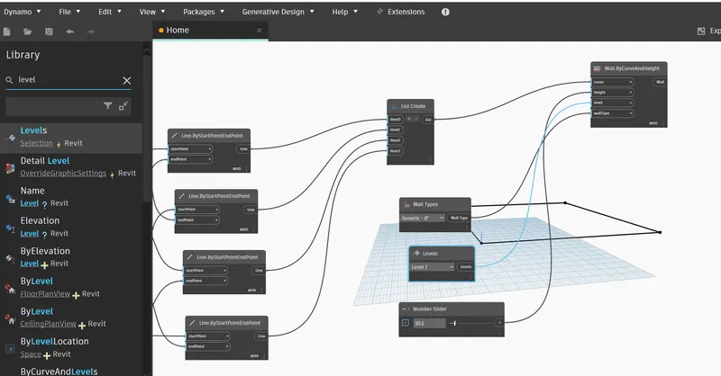
- Thus the wall will be created in the Revit project as shown below
- The height of wall can be adjusted by moving the slider for adjusting required height and similarly in case of open wall the slider can also provided to length to adjust the length as required from the slider.
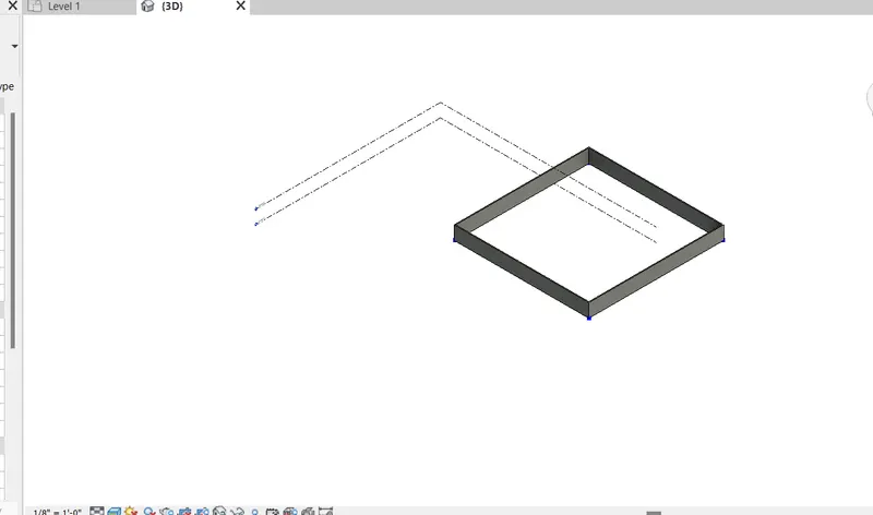
CONCLUSION: Thus we have created the Room by creating the walls from the Points and Lines in Dynamo by providing the required input for wall type and slider input to adjuct the height of the wall.
3) Create an array of model elements in Revit. Use dynamo to vary the properties of model elements by using the slider or code block
Ans 3.
INTRODUCTION: Creating an array of model elements in Revit and varying its properties by using silder or code block using Dynamo
AIM: To create an array of model elements in Revit and using Dynamo to vary the properties of model elements using the slider or code block.
PROCEDURE:
- Create 4 column elements in the Revit project
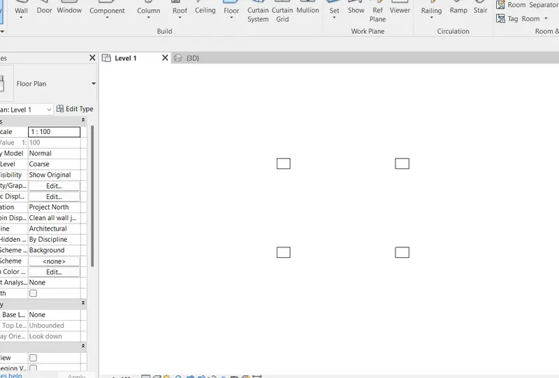
- Open the Dynamo from Manage tab
- Enter Model in the library and create the Select Model Elements command
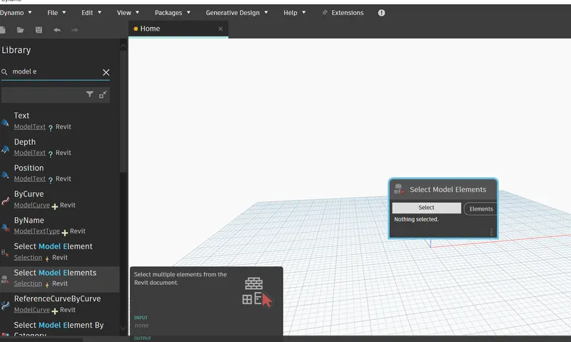
- Go to the Revit project and select the columns
- In Dynamo the ID of the selected 4 columns elements will be seen
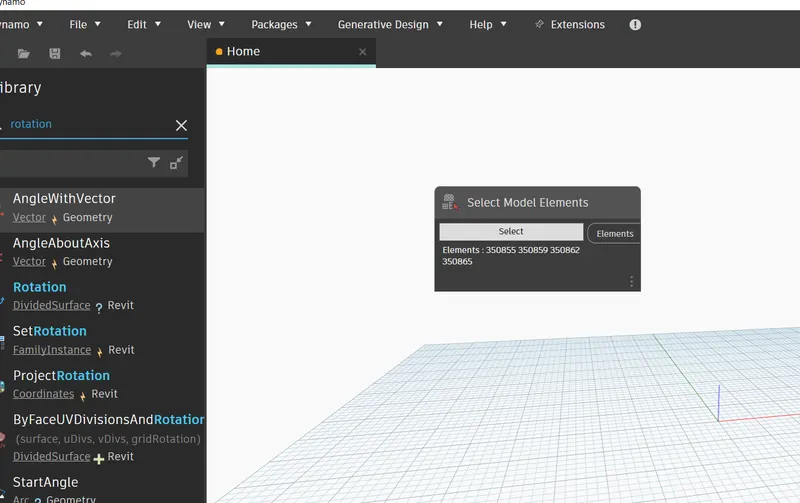
- In library search for Rotation and select the command Family instance set rotation.
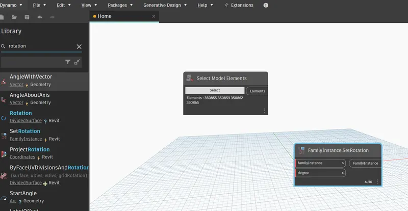
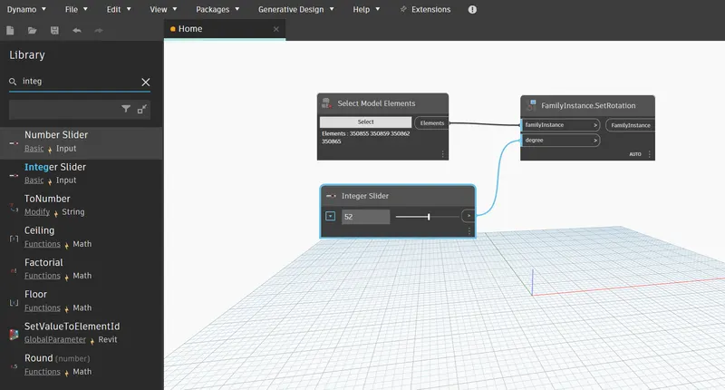
- Provide input of selected model elements to the Family instance
- Create a slider for the degree of rotation and provide input to the degree for family instance set rotation command
- Slide the slider value to reqiured degree
- Go to Revit project and check the rotation of the columns will be done from the Dynamo slider as shown below
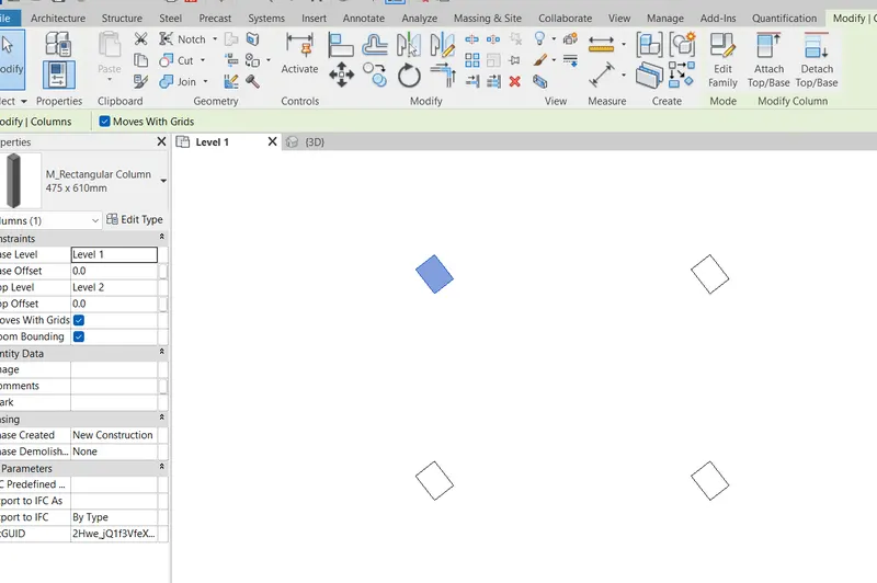
CONCLUSION: Thus we have created the model elements in the Revit project and then by selecting the elements in the dynamo we have varied the properties of the element by using Slider.
4) Create a conceptual mass in Revit and develop a parametric column by dividing the surfaces and apply the concepts similar to used in parametric walkway modelling. Use triangular bent or square shaped panels to add finish to the parametric column
Ans 4.
INTRODUCTION: Creating conceptual mass in Revit and developing the parametric walkway model.
AIM: To create a conceptual mass in Revit and develop a parametric column by dividing the surface and applying the concept to model a parametric walkway usin the triangular bent of square shaped panels.
PROCEDURE:
- In Revit go to File and open new Conceptual mass
- Create the levels of require height for the mass to fit in the two levels
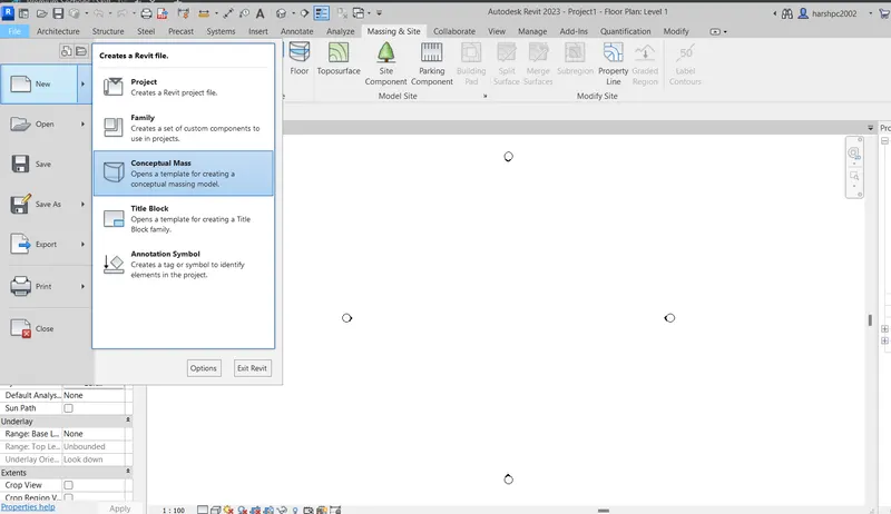
- In 3D view of the conceputal mass create the curve using the Spline model line
- On the points of the curve of the spline set the work planes by selecting Set Work Plane tab
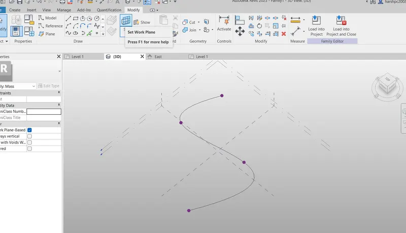
- The work planes are set as shown below
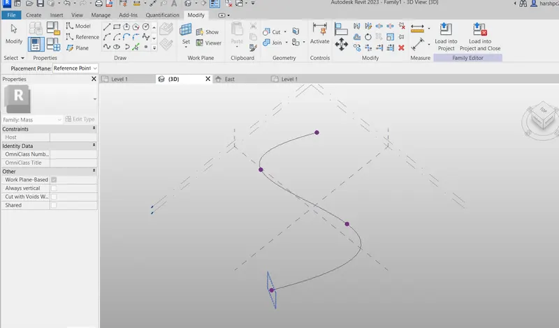
- Place a polygon on the Work planes set on the spline curve.
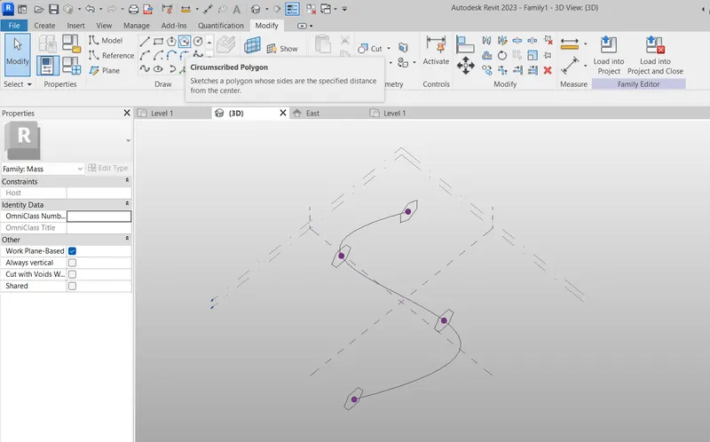
- Select the spline curve and one of the polygon and create solid form from the Creat Form tab
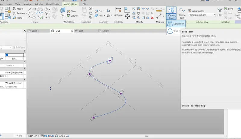
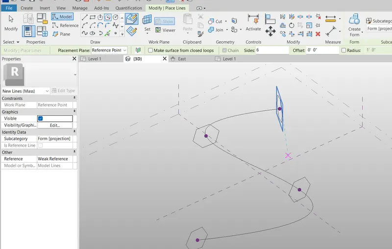
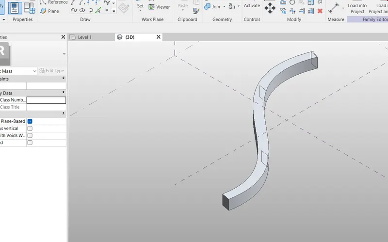
- Thus the Solid form of Polygonal section is created along the spline
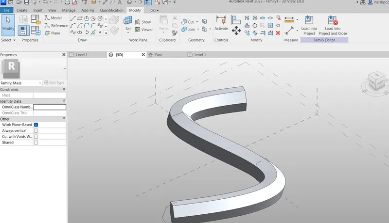
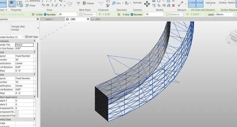
- Select the solid form and provide the divided surface by selecting the require pattern from the properties
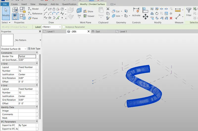
- Rectangular pattern is selected for the divided surface.
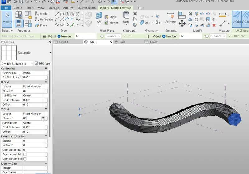
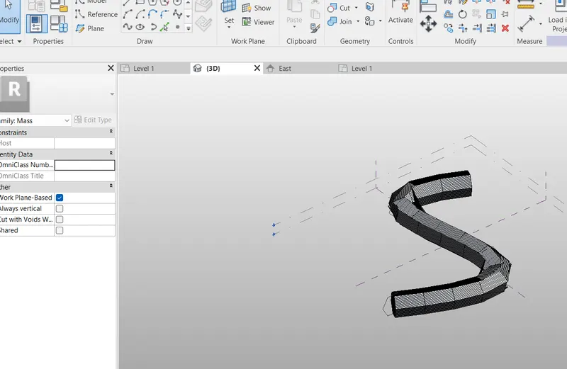
- The number of the grids on U grid and V grids can be changed to get the smooth surface of the mass
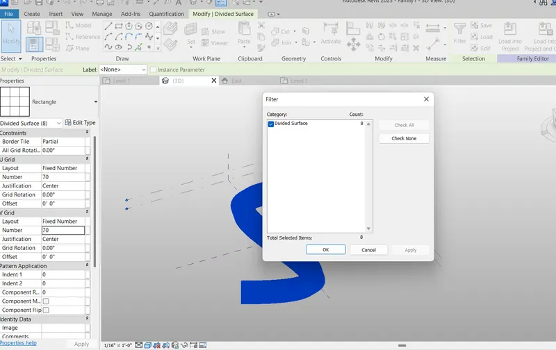
- Similarly the Triangular pattern can also be provided as shown below
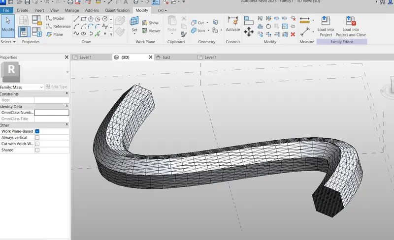
- The Conceptual mass can be saved as a Family in required folder
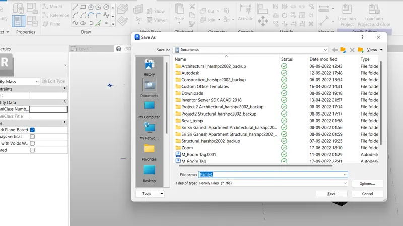
- Create Rectangular form for the walkway model as shown
- Create as family using curtain wall for the triangular bent shape and apply to the surface of the model as shown below.
- Thus a parametric walkway model is creates with triangular bent as shown below.
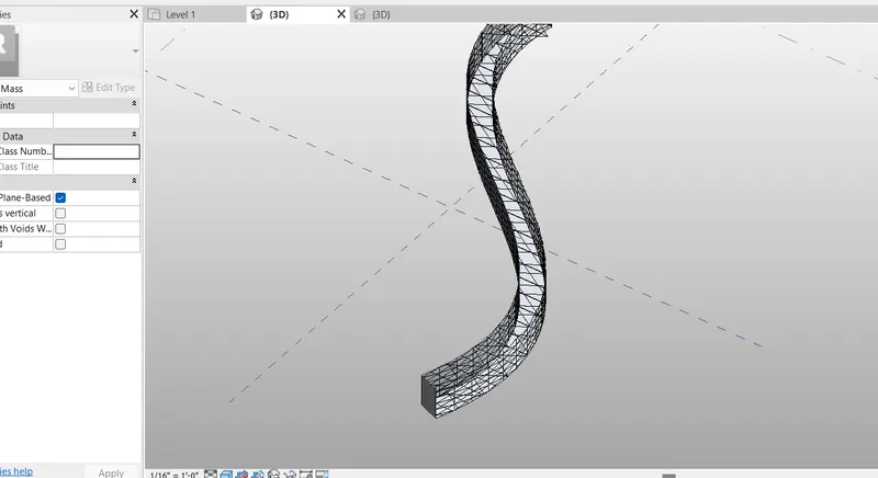
CONCLUSION: Thus we have created a Conceptual mass using the rectangular and triangular divided surface in Revit and based on similar concept we have designed a parametric walkway model by providing the divided surface
5) Use Dynamo to work on developing a Parametric Stadium. List your parameters and use the visual programming approach to complete the modelling, You can use the concepts discussed in parametric high rise tower in class for reference.
Ans 5.
INTRODUCTION: Creating a Parametric Stadium using Dynamo
AIM: To create parametric stadium using Dynamo and listing the parameters and using visual programming approach to complete the modelling.
PROCEDURE:
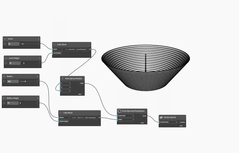
- We will be creating a parametric stadium concept of conical shape by using various codes and commands in the Dynamo by creating circles and then creating surface form which can be altered by using sliders
- Create the code for Levels, Level Height, Radius and Radius height by using slider.
- Create Code block for Levels and Level heights by input from Levels and Level heights sliders
- Similarly create Code block for Radius and radius heights by input from the radius and radius height sliders
- Provide the base radius in the Radius Code for the minimum base of the stadium floor
- Create the Points by coordinates code.
- Provide inputs to points from the Levels and level heights
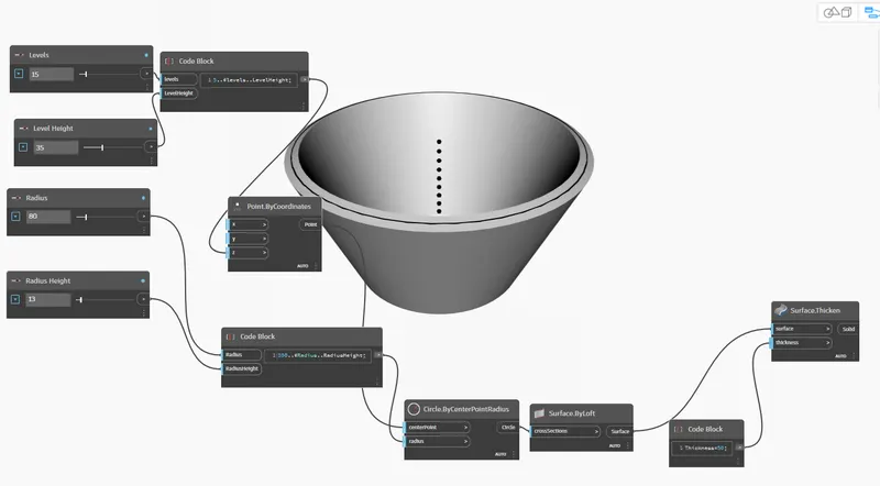
- Create Circle by center and radius code by providing the inputs from Points by coordinates code and Radius code block
- The circles of various radius with lower at bottom and bigger radius at top will be formed.
- Create the surface by Loft code to create a surface around the circles formed.
- Thus the conical shape for the stadium concept is formed as shown below
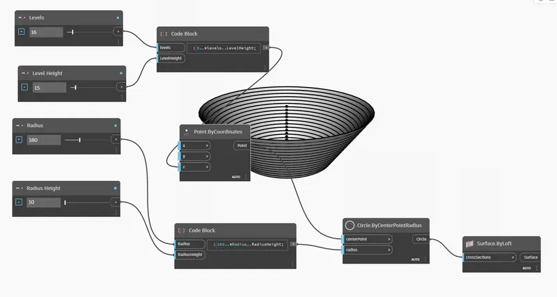
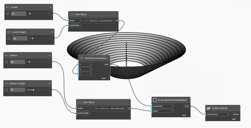
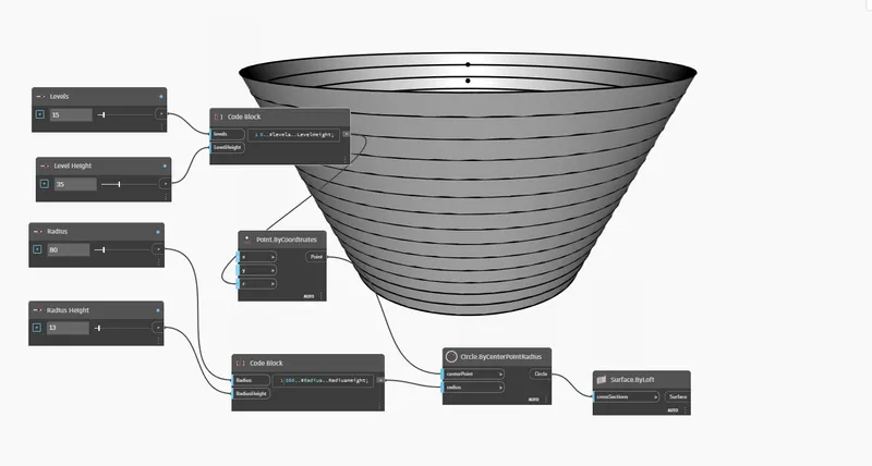
- The height or radius of the structure form of stadium can be varied using the sliders provided for levels, heights and radius as shown below
- The structure form created in the Revit project is shown below.
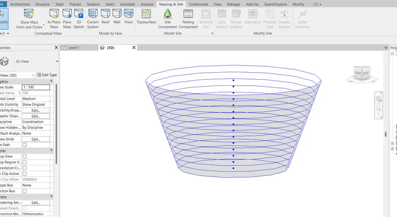
- Thickness to the form can be provided by creating the Surface thicken code and giving the input of Thickness code block as shown below
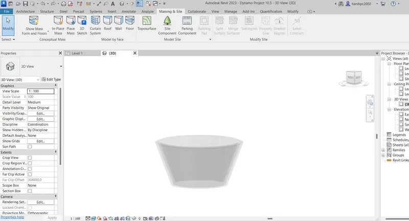
- Realisting view of the structure form is shown below in Revit
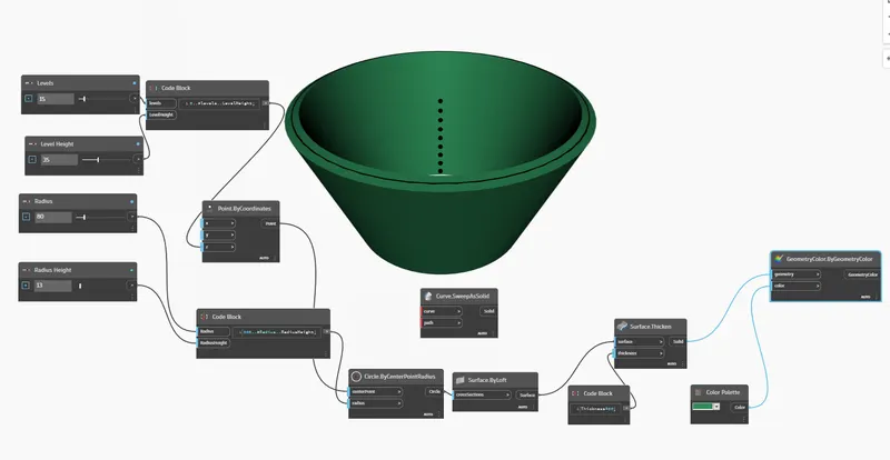
- Color to the structure form can also be provided by creating the Code for Geometry Color byGeonmetry color and using the colour pallete code
CONCLUSION: Thus using Dynamo we have created the Parametric Stadium structure form using various codes.