Creating Conceptual mass in REVIT and Creation of Sinusoidal curve and a Parametric stadium using Dynamo
Question 01) Using Dynamo create a set of sinusoidal points and create a curve and create a surface out of the curve.
Answer:
Aim: To create a set of sinusoidal points and create a curve and also to create a surface out of the curve.
Dynamo enables designer to create visual logic to explore wide range of parametric conceptual designs using logic, simple data analysis without creating prototypes.
Introduction:
- Dynamo is a graphical programming interface which provide customization of building information workflow.
- Dynamo can help to get things done faster with minimal effort by automating repetitive tasks. This in turn speeds deign processes and improves efficiency.
- Rather than typing code, with Dynamo helps in creating programs by manipulating graphic elements called “nodes”.
- In Dynamo, each node performs a specific task.
- Nodes have inputs and outputs, the outputs from one node are connected to inputs of another using “wires”.
- The program or “graph” flows from node to node through the network of wires.
- The result is a graphic representation of the steps required to achieve the end design.
Procedure:
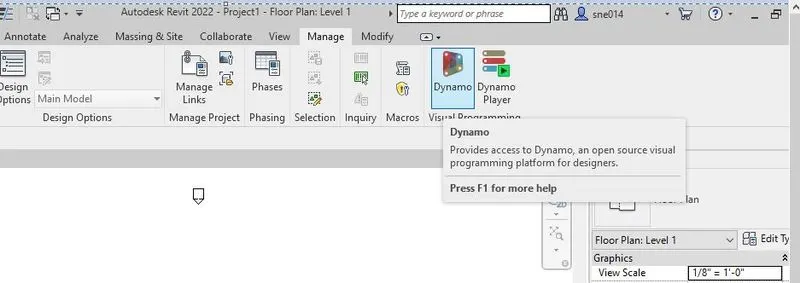
- To start with, Open the Revit software and open a new project. Then in the ‘Revit software’ in the manage tab double click on ‘Dynamo’.
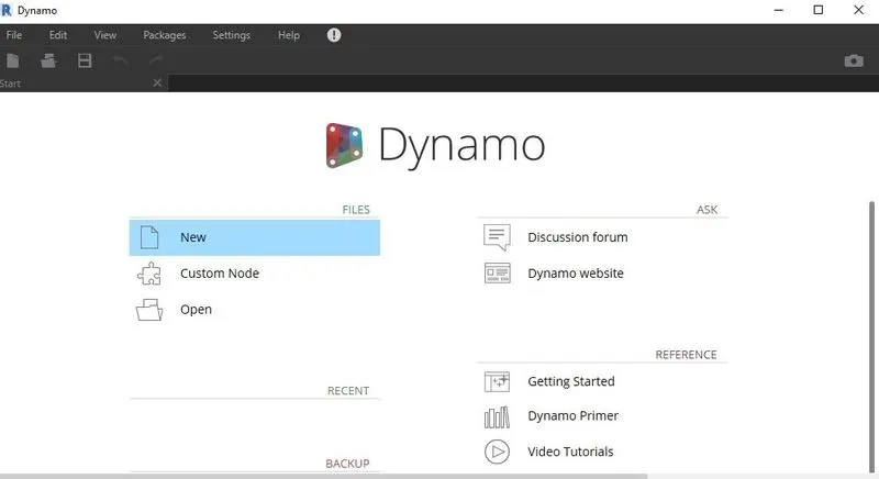
- A new window will appear. Now click on ‘New’ to create a new file in Dynamo.
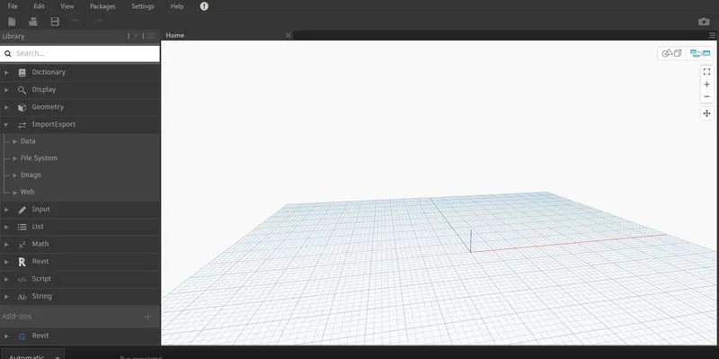
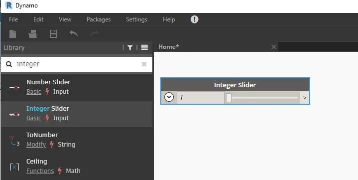
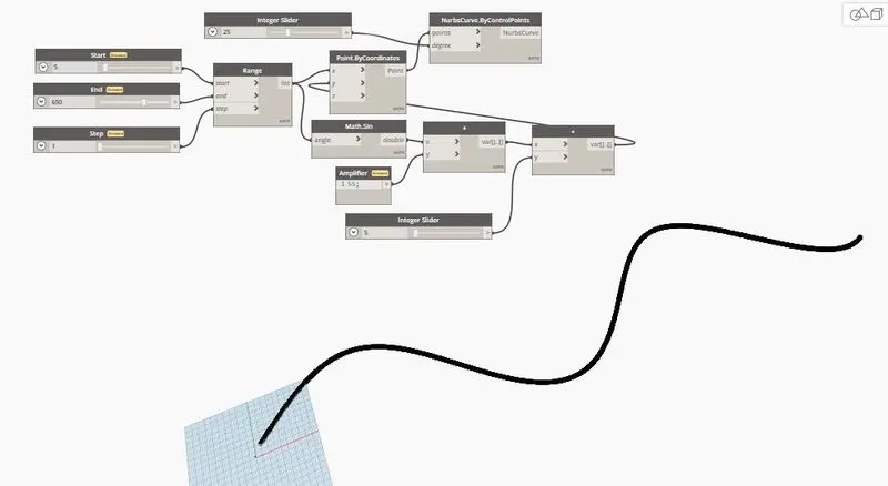
- To start with the Dynamo, type ‘Integer slider’ in the search menu. Then a small box of integer slider has opened on the screen. It has three dropdowns min, max and step which can be adjusted accordingly.
- Like-wise insert 3 integer sliders and rename them as ‘Start, End and Step’ and give the max range as 5 and 200 and 1 as shown.
- Now type ‘Range’ in the search box and connect all the three Start, End and Step Integer sliders to ‘Start, End and Step’ of the Range box.
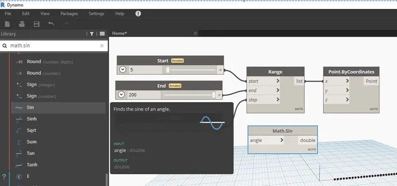
- Now type ‘point by coordinates’ in the search box and click to add. Now connect the ‘List’ of the Range to the Angle of ‘Math sin’.
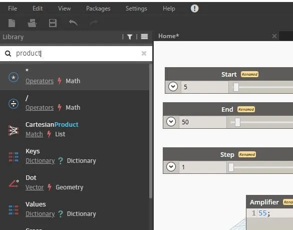
- Now type ‘product’ in the search bar and add ‘* box’. Connect ‘Math.sin’ to ‘x of the product’.
- Now double click on the screen to add a code block and rename it as ‘amplifier’. And set the value accordingly.
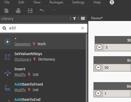
- Now add ‘integer slider’ and give the range. Connect it to ‘y of the add’. Now connect ‘var of the add’ to the ‘y of the point by co-ordinates’.
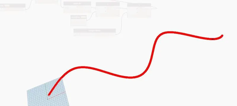
- Now type nurb’s curve by control points’ and connect ‘points of the coordinates’ to the ‘points of the nurb’s curve’ Add again one integer slider and connect to the ‘y of the nurb’s curve’. Now sinusoidal curve will be visible.
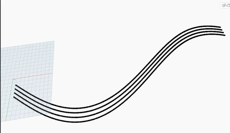
- Now copy all the group and paste it 3 times on the screen to add 3 more sinusoidal curves and change the number in the integer slider in the incremental order of 5 which has been connected to the degree of the nurb’s curve.
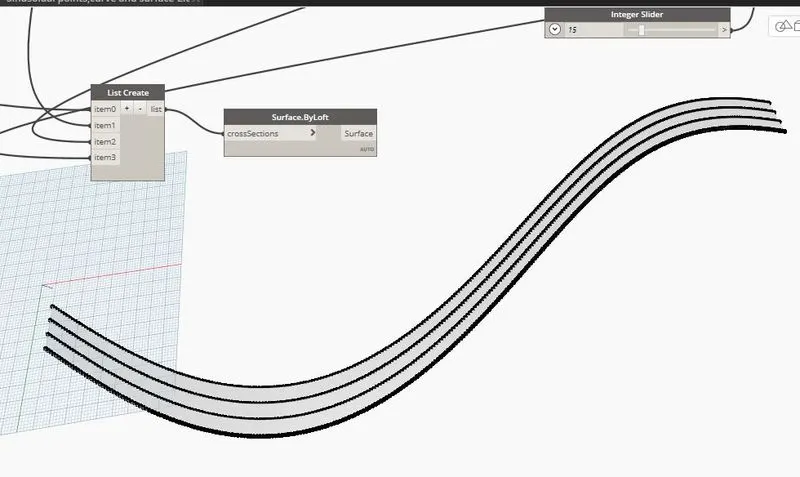
- To create surface, first we need to type ‘list create’ in the search bar and create 4 items in that list. Connect all the nurbs curve to the 4 items.
- Now type ‘surface by loft’ in the search bar and add it to the dynamo screen. Now connect the list to the cross section of the surface by loft. Surface will be created as shown.
Result:
Question 02) Create a conceptual layout of floor plan in dynamo. Using the tools available in dynamo link the lines to appropriate model elements in Revit by choosing the wall types and wall parameters. Make use of the sliders to slide through the height of the wall and length of the wall.
Aim: To create a conceptual layout of floor plan using tools available in the dynamo link.
Procedure:
- Open a new file in Dynamo and add 2 integer sliders to the dynamo screen and rename them as x and y and give minimum integer number as100.
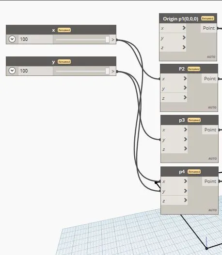
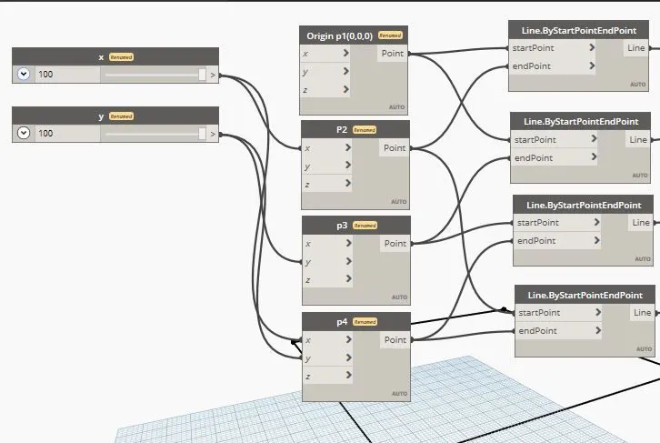
- Now add point by coordinates 4 times and rename them as p1, p2, p3, p4 and connect x and y as shown. Now 4 nodes will be created in the Dynamo screen.
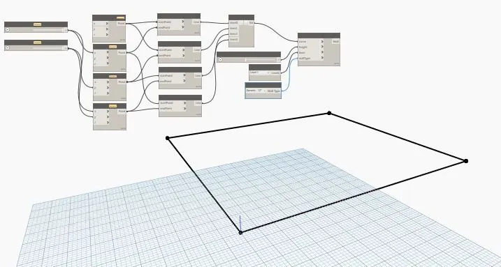
- Now type Line by ‘start-point end-point’ and add it 4 times. Now connect the all the points with line start point to end point as shown. A rectangle will be created in the dynamo screen.
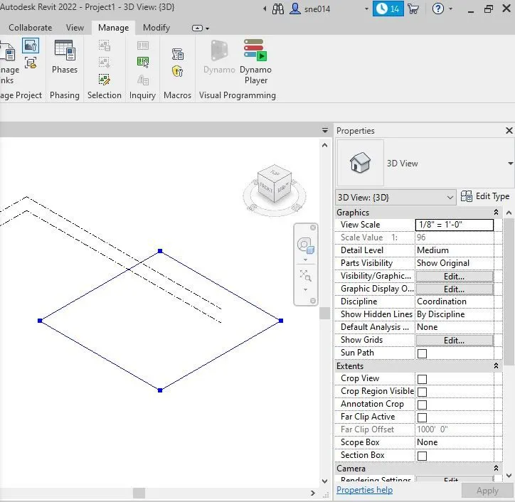
- Now minimize the Dynamo screen, On the Revit Software screen A big Rectangle will appear. Now click for 3d view and change the visual style to shaded. A big 3d rectangle will be seen.
- Now add ‘List create’ and create 4 items in the box and connect all the 4 lines to the ‘List create’. Now add ‘wall by curve and height’ and connect the List to the Curve.
- Now add 1 integer slider and rename it as wall height, add 1 Level box and 1 Wall type box to the Program. Now connect ‘Wall height to Wall Height’, Level to Level’, and ‘Wall type to Wall type’.
- Now we change the height of the wall, Type of the wall from Dynamo only.
Result:
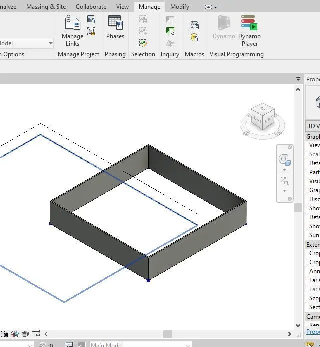
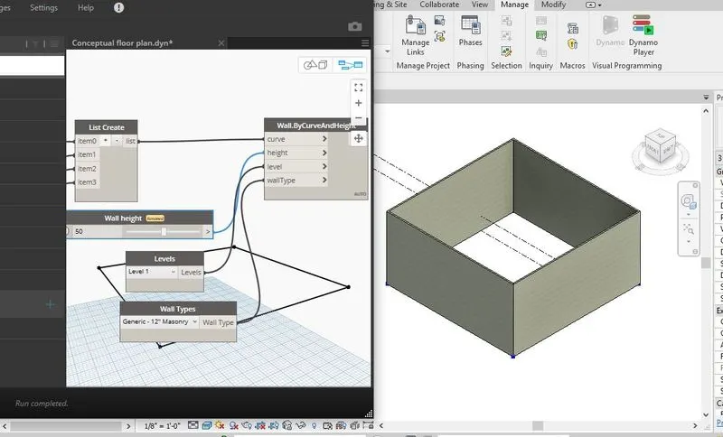
Question 03) Create an array of model elements in Revit. Use dynamo to vary the properties of model elements by using the slider or code block
Answer:
Aim: To create array of model elements in Revit. Using Dynamo to change the properties of model elements.
Procedure:
- Open the Revit software in Architecture template.
- Now go to Architecture ‘tab click on Columns select columns architecture and add columns in Revit screen.
- Now go tot the ‘Manage tab’ and press on ‘Dynamo’ Now Open new file in the Dynamo.
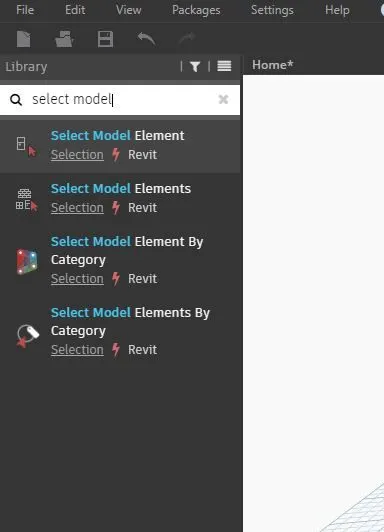
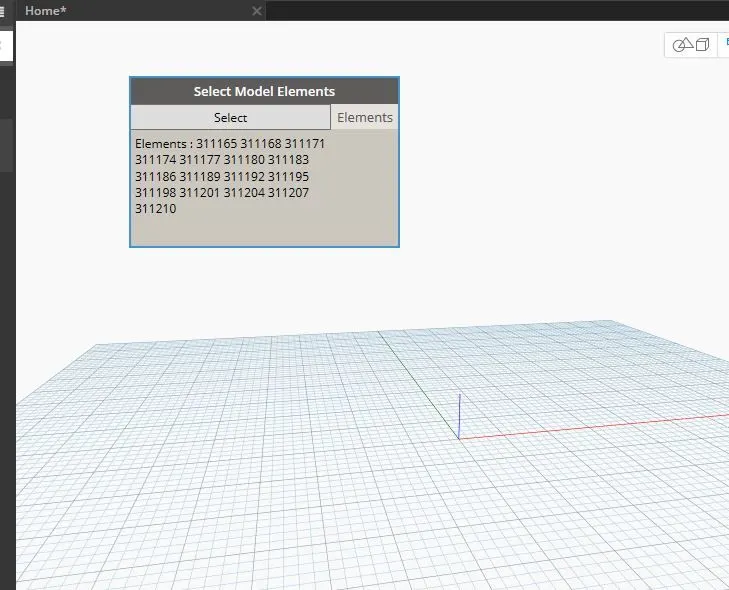
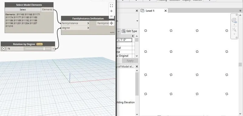
- Now in the search tab press ‘Select Model Elements’ add it to the workspace. Now in the ‘Select Model Elements’ box click on select and minimize the screen and in the Revit software select all the columns.
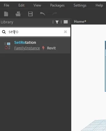
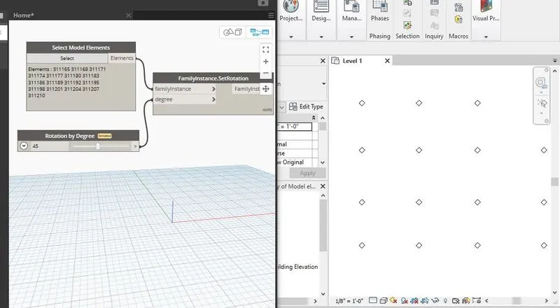
- Now add ‘set by rotation’ and 1 ‘number slider’ rename it as ‘Rotation by degree’. Now connect ‘Elements’ to the family instance and ‘Rotation by degree’ to the ‘Degree’.
- Now change the Degree in the ‘rotation by degree’ as 45° and automatically all the columns in the Revit software will aligned to 45°.
Result:
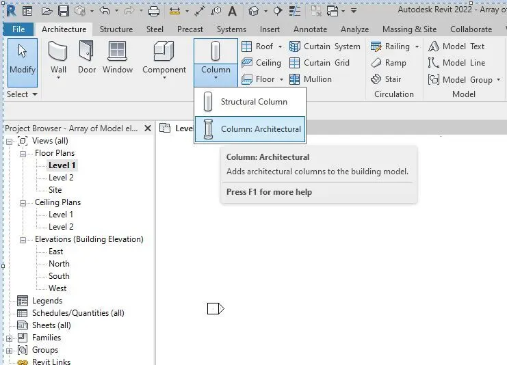
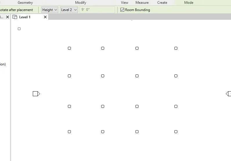
Question 04) Create a conceptual mass in Revit and develop a parametric column by dividing the surfaces and apply the concepts similar to use in parametric walkway modelling. Use triangular bent or square shaped panels to add finish to the parametric column.
Answer:
Aim: To create a conceptual mass in Revit and develop a parametric column by dividing the surfaces and apply the concepts similar to used in parametric walkway modelling.
Procedure:
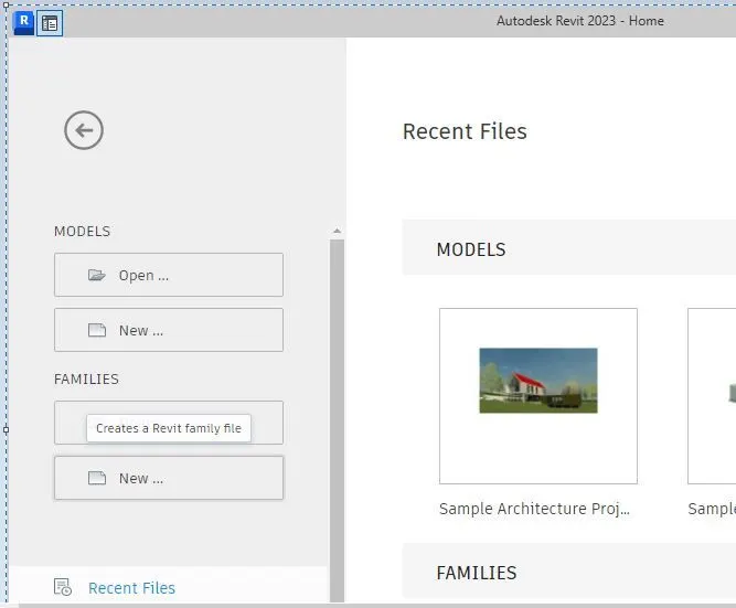
- Open Revit Software. Then go to Families and click ‘New’ in the new window select ‘Family templates’ and click on ‘Conceptual Mass’ and lastly click on the ‘Mass’ icon.
- Now a new Conceptual Mass screen will be opened.
- Now in the ‘3d view’ go to the ‘top view’ screen will appear in top view.
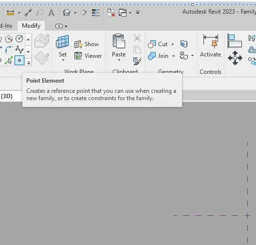
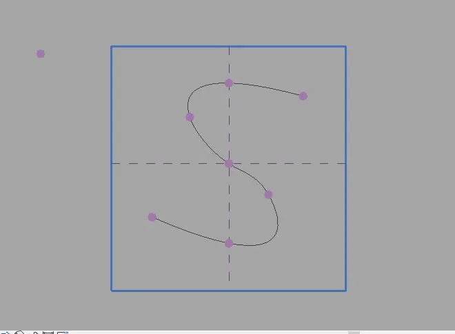
Now go to the’ Modify’ tab and click on ‘Point element’. Draw points on the screen by changing the offset elevation in the ‘properties’ tab.
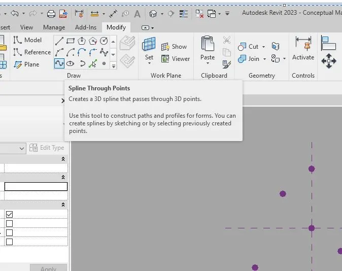
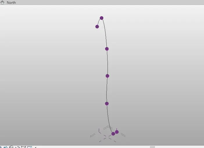
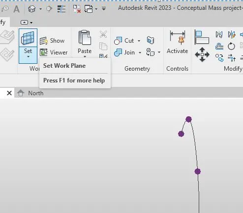
- Now draw ‘sp line’ connecting all dots. Now go to ‘Set’ and click on ‘Set Work Plane’ on all the dots separately and draw ellipses on the dots.
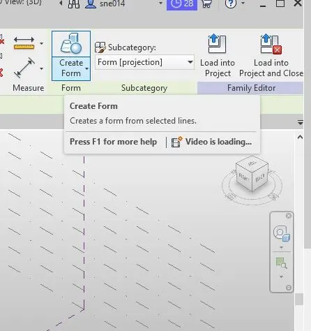
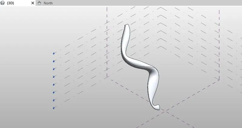
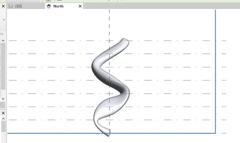
- Now select all the ellipses and click on ‘create form’. A parametric column will be created.
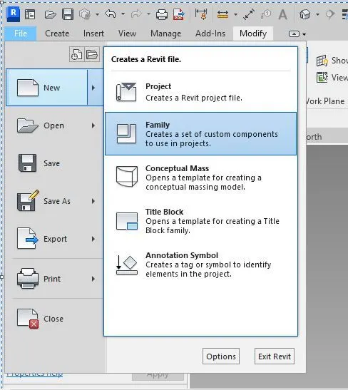
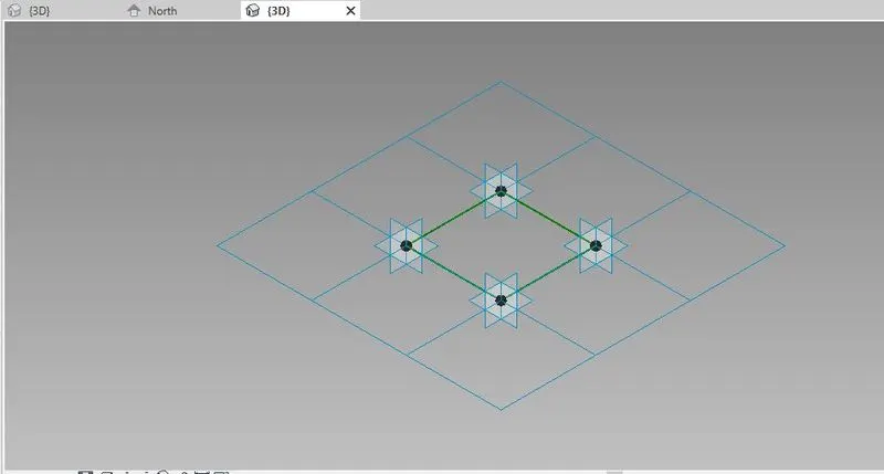
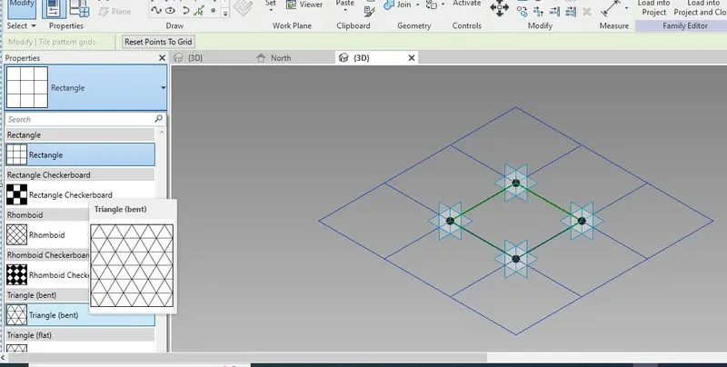
- Now for applying ‘triangular bent’ click on ‘file’ and then on ’new’ and finally click on ‘family’ and open ‘Metric curtain panel pattern based’. Now the screen will appear as shown.
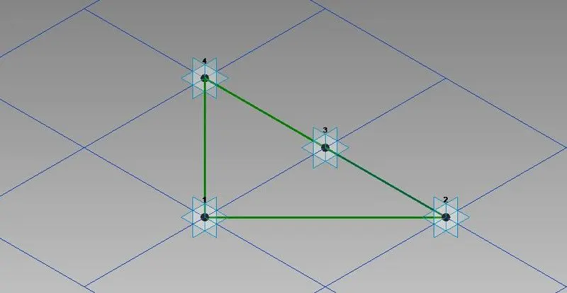
- Now select the ‘Grid’ shown on screen and now go to properties bar an change the grid to ‘triangular bent’. Now select the node set work plane and draw a square of 100m width along the plane.
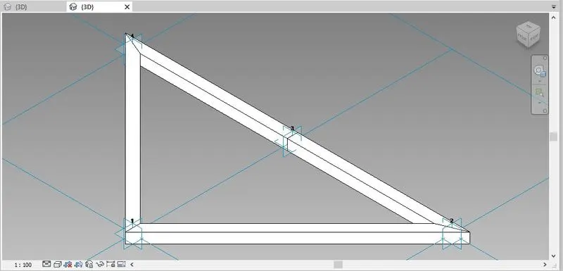
- Now select the square and triangle and click on ‘create form’. Now hide the glass bent and create framework by selecting triangle and clicking on ‘create form’ Now change the positive offset in the frame work to 10 and material to glass and finally unhide the glass work and save the bent created with a proper name.
- Now select the bent and click on ‘Load into the project’.
Result:

Question 05) Use Dynamo to work on developing a Parametric Stadium. List your parameters and use the visual programming approach to complete the modelling, You can use the concepts discussed in parametric high rise tower in class for reference.
Answer:
Aim: To create a parametric stadium using Dynamo.
Procedure:
- Open a new file in Revit in Architectural template and open Dynamo in that.
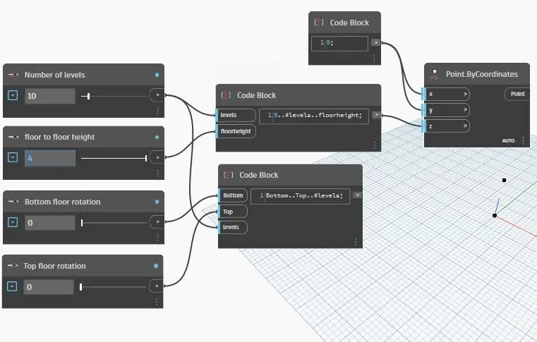
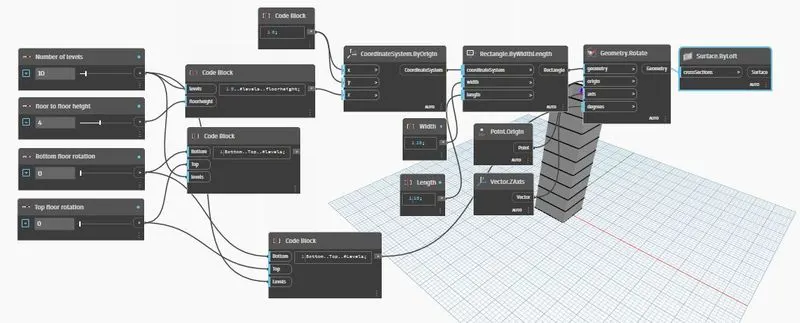
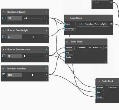
- Now add 4 integer sliders and rename them as a) number of levels, b) Floor to floor height, c) Bottom floor rotation and d) Top floor rotation.
- In the ‘number of levels’ integer slider set the Min and Max value as 0 and 100 and step as 1. In the ‘Floor to Floor height’ slider set the Min and Max values as 0 and 10 and step as 1. In the ‘Bottom floor rotation’ slider set the values as 0 and 180° and step as 1. In the ‘Top floor rotation’ slider set values as 1 and 400° and step as 1.
- Now add code block and enter the required code. Now connect no of levels to the levels and floor height to the floor height.
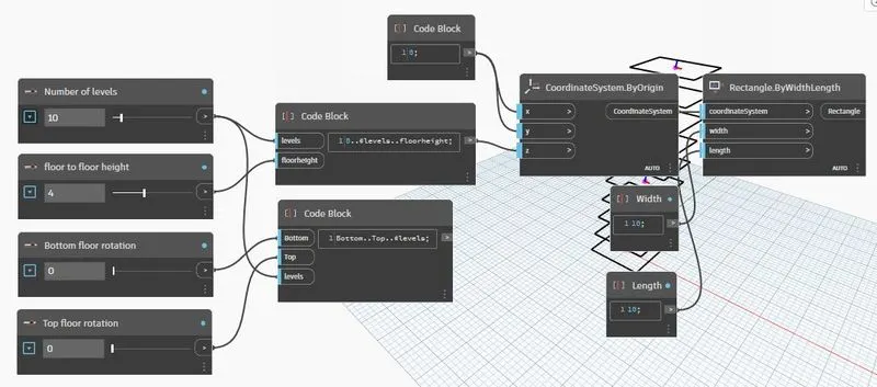
- Now add coordinates by origin slider and connect code block to the ‘z axis’ of the coordinates by origin. Now add one more code block to connect to the x and y of the ‘coordinates by origin’.
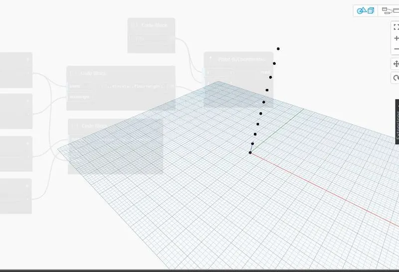
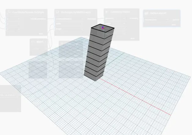
- Now change the value in ‘number of levels’ slider to 10 and ‘floor to floor height’ to 5. Following set of nodes will appear on the screen.
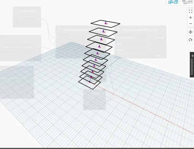
- Now to create rectangles add one ‘rectangle by width and length’ coordinate system to screen. Now connect ‘coordinate system by origin’ to coordinate system of the ‘rectangle by Width Length’. Add two more code blocks, rename them as width and Length and connect them to Width & length of the Rectangle. Give values for Width & Length of the code blocks as 10,10. Now rectangles are created along the levels.
- Now add ‘Geometry rotate’ and connect the rectangle to geometry rotate. Add ‘point origin’ and Z-axis vector and connect them to origin and axis to the z axis.
- Add one code block to connect it to the Bottom floor rotation, Top floor rotation and number of Levels. Connect this code block to the degree of rotation.
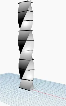
- Now lastly add poly surface by loft. Add geometry to the poly surface by loft. Now parametric stadium is created.
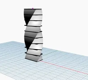
- Now change the ‘floor to floor height’ to 5 and ‘top floor rotation’ to 180 now we can see the structure rotation. Change the values of all the 4 starting integer sliders and see the changes in the parametric stadium accordingly.
Result: