Creating Conceptual mass in REVIT and Creation of Sinusoidal curve and a Parametric stadium using Dynamo
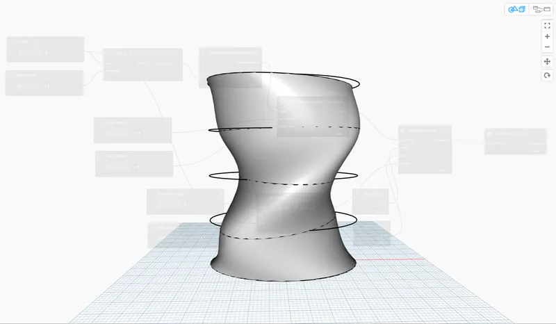
1) Using Dynamo create a set of sinusoidal points and create a curve and create a surface out of the curve.
Aim:
To create a set of sinusoidal points and create a curve and create a surface out of the curve.
Introduction:
Dynamo is a open source visual programming language for revit. This allows to type lines of code and also creating an algorithm that consists of nodes. Each node perform a specific task and each node consists of input and output. The output from one node is connected to the other node in from of wires. The program flows from one node to other node through the wire networks and the final output is the graphical representation of a model.
In this project, I create a set of poins in the x-axis by using nodes and connect to the other nodes to form a sinusoidal curve and make simalar curves by grouping the nodes and change some parameters. Finally make a surface through the sinusoidal curve.
Procedure:
- Open a new project with architectural template.
- Select 'Dynamo' under manage tab.
- Once the dynamo window opens, Select new.
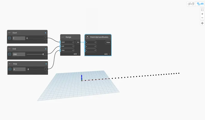
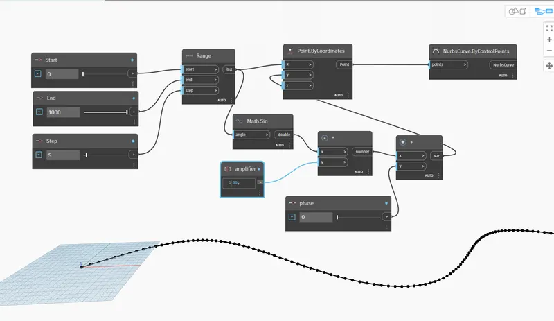
- First Create a set a points in the X-axis.
- For that, Introduce three integer sliders and rename it as start, end and step.
- Introduce one range node and Points by coordinates node.
- Connect the wires from sliders output to range input and range output to points by coordinates input in the X Coordinate.
- Now create a sinusoidal pattern from the points created.
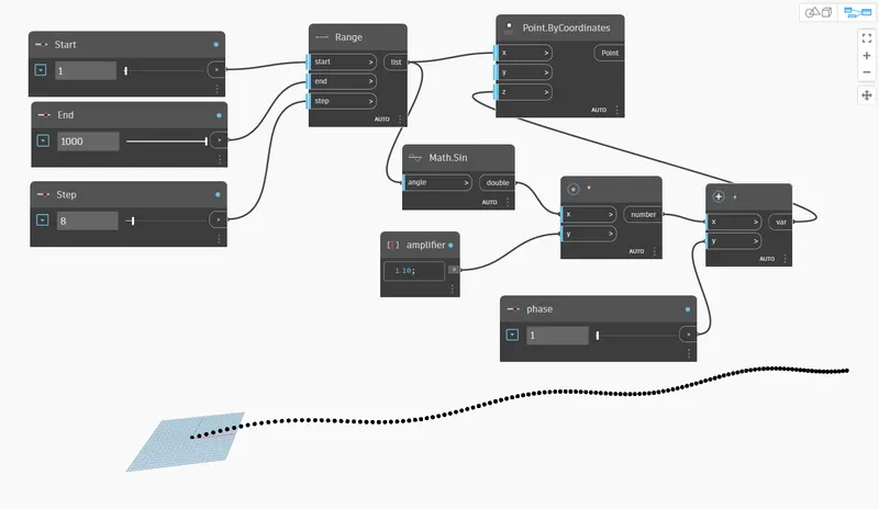
- Introduce math.sin, Integer slider, Code block, product and addition nodes.
- Rename the code block as amplifier and set the value as 10.
- Connect the range output to the math.sin input.
- Connect wire from math.sin output to Product node input X and amplifier ouput to product input Y.
- Connect Wire from product output to Addition input X and Integer slider to addition node Y.
- Finally connect the wires from product output to the points by coordinates input in the z-axis.
- Create a Line that connects the sinusoidal points.
- Create a nurbscurve by coordinates node.
- Connect the wire from proints by coordinates to nurbscurve by coordinates.
- Create a similar sinusoidal curves.
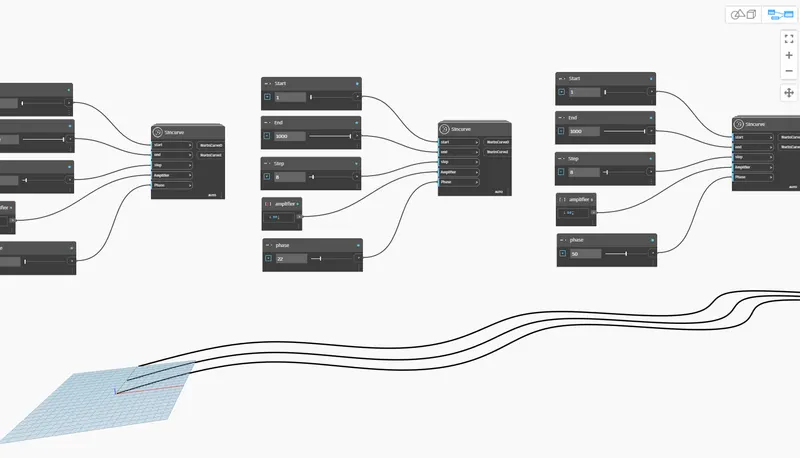
- For that create Custom node from all the outputs.
- Select all the output node and select create custom node in the edit tab.
- Then name it as Sin curve, Write the discription and select the categories as revit.
- Once the group is Created.
- Select all the nodes and make two more copies.
- increase the phase values as 22 and 50 for the another two copies.
- Now create a surface through the sinusoidal points.
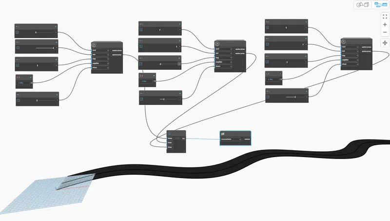
- Introduce list and Surface by loft nodes.
- Connect the wires from All the nurbs cure to the list.
- Finally connect the wire from list output to nurbs curve by loft input.
Result:
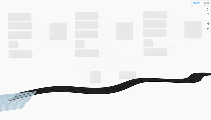
A set of sinusoidal points and curve is created and surface is created out of the curve.
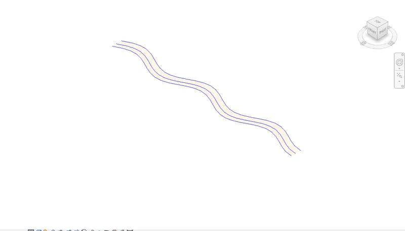
2) Create a conceptual layout of floor plan in dynamo . Using the tools available in dynamo link the lines to appropriate model elements in Revit by choosing the wall types and wall parameters. Make use of the sliders to slide through the height of the wall and length of the wall.
Aim:
To create a conceptual layout of floor plan in dynamo.
Introduction:
In dynamo nodes are objects these connect to form a visual program. Each node performs an operation, sometimes as simple as storing a number or it may be a complex action such as creating geometry. The geometry created by using nodes is replicated in the revit.
In this project, I create a nodes that perfoms an operation like inserting points, Creating walls and floors by connecting the nodes by using wires.
Procedure:
- Open a new project with architectural template.
- Select 'Dynamo' under manage tab.
- Once the dynamo window opens, Select new.
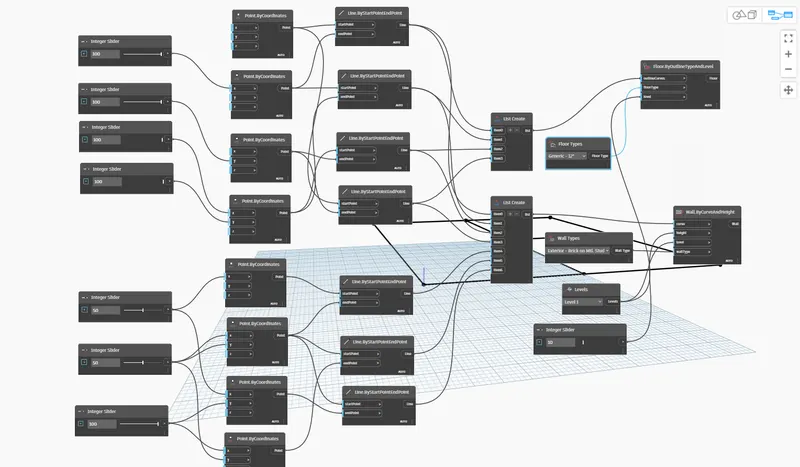
- First create a points to connect the outline of the floor plan.
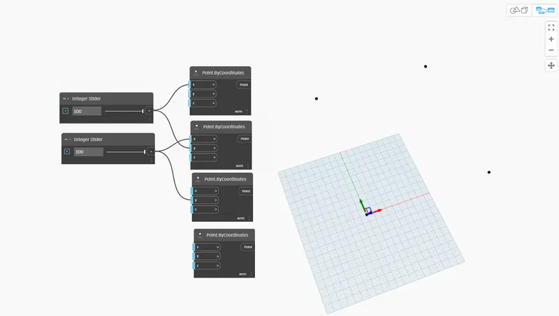
- For that introduce two integer sliders and four points by coordinates nodes.
- Set the value as 100 in integer sliders.
- Connect the wires from the integer sliders to points by coordinates inputs.
- Connect the wires as shown in the figure below.
- That creates the points at the orgin, 0,100 , 100,100 and 100,0
- Now to create a points for the internal walls.
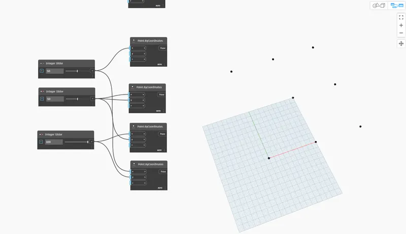
- Again introduce three integer sliders and four points by coordinates nodes.
- Set the values as 50 and 100 in the integer sliders.
- Connect the wires from the output of integer sliders to input of points by coordinates node as shown in the below figure.
- This create a points 0,50 , 50,50 and 50,100
- Create a line through the points to make a conceptual layout.
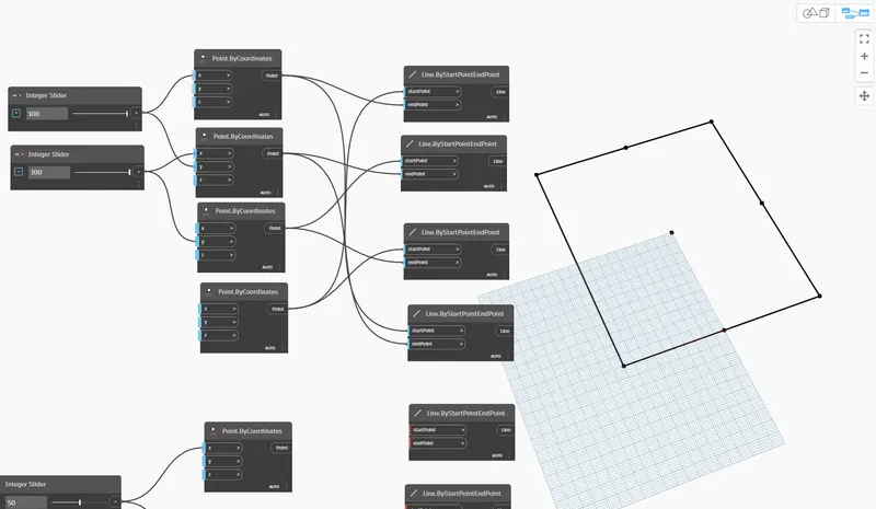
- For that introduce four line by start and end point nodes.
- Connect the wires from the points by coordinates to line by start and end point nodes.
- Connect the wires like the below figure.
- This create a out line of the conceptual floor plan.
- Create internal wall lines.
- For that again introduce three line by start and end points node.
- Connect the wires from the points by coordinates to line by start point and end point nodes.
- Connect the wires like the below image.
- This create the lines in the internal points.
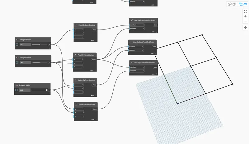
- The conceptual line layout is created.
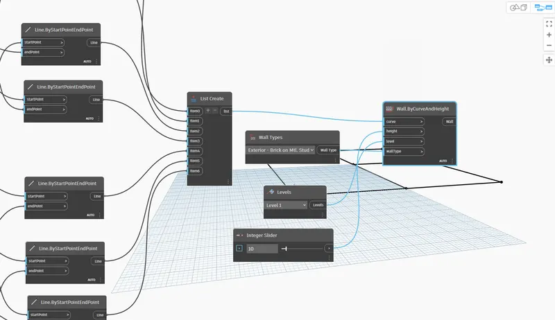
- Now create a Wall.
- For that introduce list node.
- Connect the wires from the points by start and end point output to the list node inputs.
- Introduce wall types node and select the wall type as 'exterior-Brick on Mtl. stud'
- Introduce levels node and set the level as 'level 1'
- Introduce integer slider for to control the height of the wall. Set the value as 10.
- Introduce wall by curve and height node.
- Connect the wires from list to curve in the wall by curve and height node.
- Connect wall types node to the wall types.
- Connect levels to the levels.
- Connect integer slider to the height in the input of wall by curve abd height node.
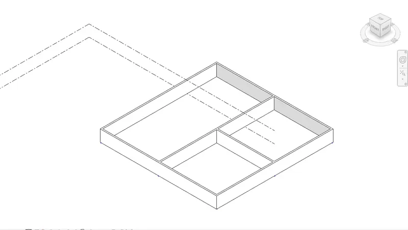
- The wall is created.
- Create a floor.
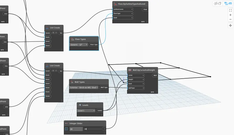
- For that introduce floor by outline type and level node.
- Introduce floor type node and select the floor type as Generic-12''
- Connect the wires for list to outline curves.
- Connect floor type to floor type in the input of floor by outline type ans level node.
- Levels to the levels in the input of floor by outline type and levels node.
- Floor is created
Result:
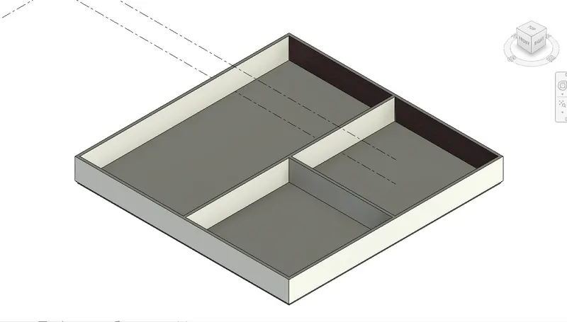
A conceptual layout of floor plan is created in dynamo.
Codes for create a conceptual layout of floor plan.
Layot reflected in revit.
3) Create an array of model elements in Revit. Use dynamo to vary the properties of model elements by using the slider or code block.
Aim:
Create an array of model elements in Revit. Use dynamo to vary the properties of model elements by using the slider or code block.
Introduction:
Array is the concept of creating copy of the element in a series manner. In this project, I create an array of a column in revit and changing the properties of the column by using familyinstance set rotate node in dynamo.
Procedure:
- Open revit software.
- Create new project by architectural template.
- Select architectural column under the arcitectural tab.
- Create one architectural column of size 24''X24''

- Make three more copies of the column.
- This will create a array of column.
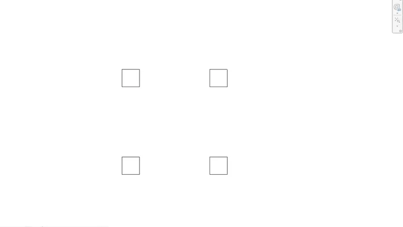
- Vary the properties of the element by using dynamo.
- For that Select dynamo under manage tab.
- open a new project in dynamo.
- Introduce Select model elements node and integer slider node.
- Family instance set rotation node.
- Click select option in select model element node.
- Now open the revit window and select all the elements.
- Then go back to the dynamo window.
- The element are selected.
- Set the value of integer slider as 45. This is the rotation degree.
- Connect the wires from select model elements and integer slider output to the family instance set rotaion input.
- Connect elements to family instance and integer slider to degree.
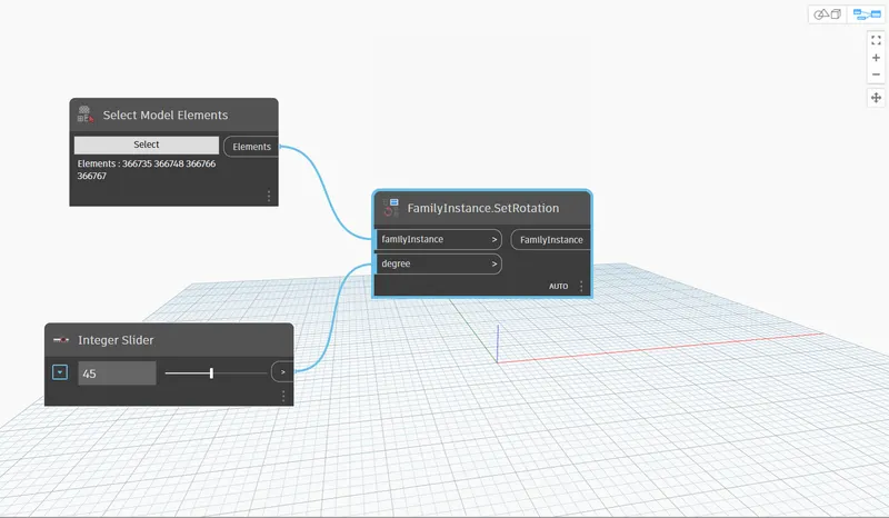
- The model element in the revit window is rotated at an angle of 45.
Result:
An array of model elements is created in revit and the properties of model elements by using the slider is varied by using dynamo.
4) Create a conceptual mass in Revit and develop a parametric column by dividing the surfaces and apply the concepts similar to used in parametric walkway modelling. Use triangular bent or square shaped panels to add finish to the parametric column.
Aim:
To create a conceptual mass in Revit and develop a parametric column by dividing the surfaces and use triangular bent to add finish to the parametric column.
Introduction:
Conceptual mass family means that the mass is external to the project. It uses the same tool to create a mass family, which is then saved and loded into the project.
In this project we create a conceptual mass of a column by using the spline curve then create a mass and add a triangular bent finish to the column.
Procedure:
- Open revit software.
- Select new families, select conceptual mass and select mertic mass.
- Create a mertic mass template.
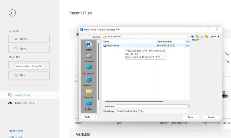
- Go to east elevation.
- Select one level at a distance of 1000 units from the existing level.
- GO back to the plan view.
- Select spline option.
- Create one spline curve.
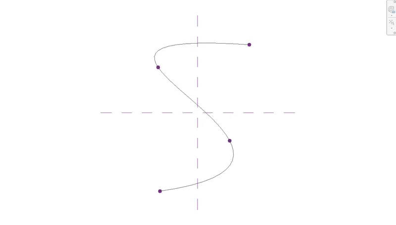
- Select set work plane option under the work plane panel.
- Set a work plane at the start point of the curve.
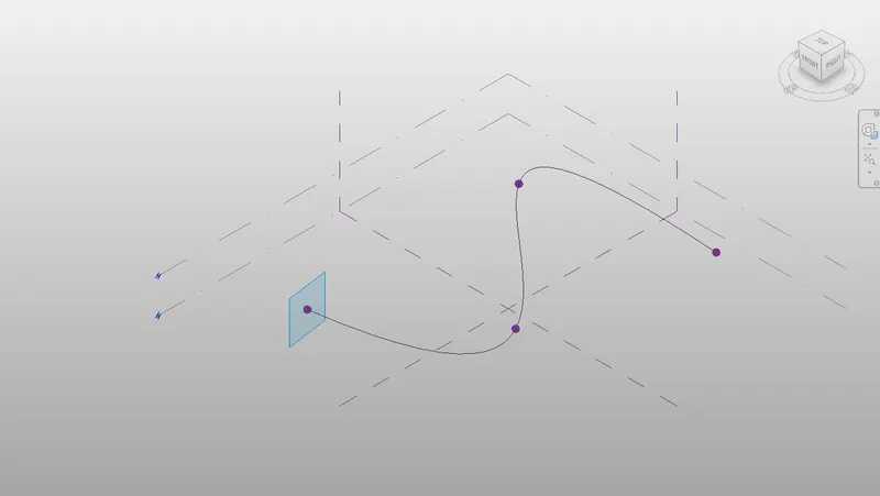
- Create inscribed polygan of 4 sides at a distance of 5000 units from the center.
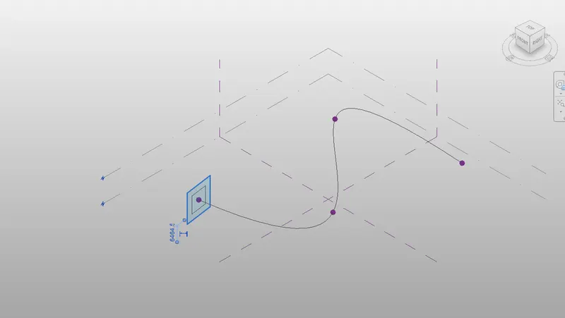
- Similarly set the work plane to all the other points.
- Create a inscribed polygan to all the work plane.
- Now create a solid form to the curve.
- Select the curve and the inscribed polygan.
- Then select solid form option.
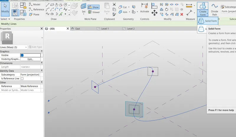
- The solid form of the curve is created.
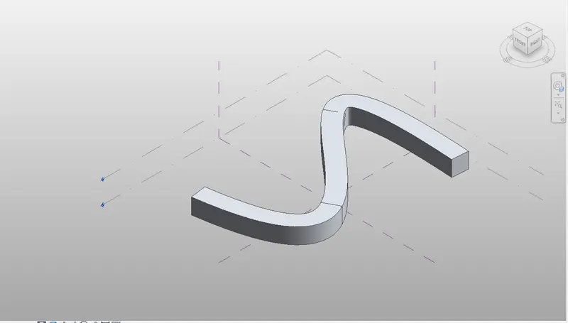
- Add triangular bent to the solid form.
- For that select the solid form and click teh divide path option.
- Select the solid form and now select the divide surface option.
- Now the model is ready to add the triangular bend finish.


- Select the triangular bents pattern under the properties browser.
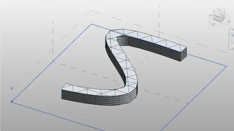
- The triangular bent pattern is applied to the model.
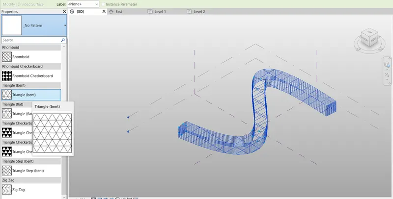
Result:
A conceptual mass template in Revit is created and a parametric column by dividing the surfaces is developed and triangular bent is used to add finish to the parametric column.
5) Use Dynamo to work on developing a Parametric Stadium. List your parameters and use the visual programming approach to complete the modelling, You can use the concepts discussed in parametric high rise tower in class for reference.
Aim:
To develope a parametric stadium by using dynamo.
Introduction:
Dynamo is a visual programming approach. This allows free to modeling any type or shape of a structure by creating nodes and connect the nodes with the help of wires the final result is the graphical representation of a model. In this project, I create a stadium that associated with the parameters. I use elliptical shape of a floor plan and the each floor is rotated to some degrees in the z-axis. This will form a different shape of structure.
Parametrs associated with the model:
- Levels
- Floor to foor height
- Radius
- Rotation
Procedure:
- Open revit software.
- Open new project by architectural template.
- Go to manage tab and select dynamo.
- open the dynamo.
- Open new dynamo project.
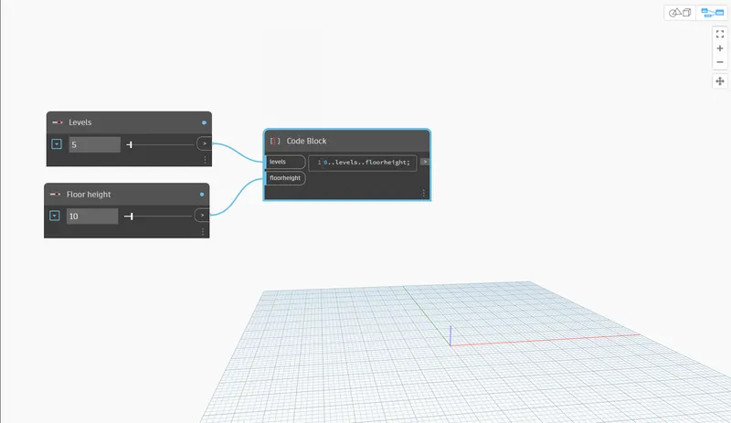
- First create a levels and floor to floor height.
- For that introduce two integer sliders for levels and floor height.
- Rename it as levels and floor height.
- Then introduce one code block and manually enter the code as '0..#Levels..floorheight'
- This code will control the levels and floor height.
- Connect the wire from levels to the levels in code block input.
- Connect wire from the floor height to floor height in code block input.
- Create points in the z axis.
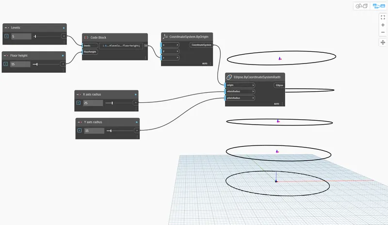
- For that introduce coordinate system by origin node.
- Connect the wire from code block output to the input of z in coordinate system by origin.
- Then create a ellipse.
- Introduce 'ellipse by coordinate system radius' and two more integer sliders.
- Rename the integer sliders as x-axis radius and y-axis radius.
- Set the radius as 25 and 15 respectively.
- Connect the wires from coordinate system output to origin of ellipse by coordinatesystem input.
- Connect wires from integer sliders to the x and y axis rotation in the input of ellipse by coordinate system.
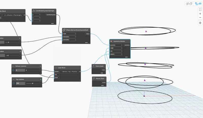
- Create rotation of the ellipse.
- Introduce a code block and write a code as 'Bottom..top..radius'
- Introduce another two more integer sliders.
- Rename the integer sliders as Bottom rotation and top rotation.
- Set the bottom rotation as 0 and top rotation as 200.
- Connect the wires to the input of code block.
- Bottom radius integer slider to the bottom of code block.
- Top radius integer slider to the top of code block.
- Leves integer slider to the levels of code block.
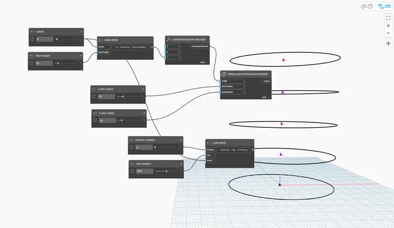
- Upto this rotation parameters are setted.
- Now create the rotation of ellipse.
- For that introduce geomerty rotate node.
- Then introduce point origin and vector z axis node.
- connect the wires to geometry rotate node.
- Connect wire from code block output to degrees.
- Connect wire from to ellipse to geometry.
- Connect wires from point origin to origin.
- Finally connect wire from vector to axis in the input of geometry rotate node.
- Rotation of geometry(ellipse) is done at 200 degrees.
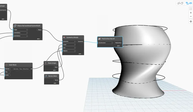
- Create a surface to the geometry created.
- Introduce 'poly surface by loft' node.
- Connect the wire from geometry to the crossection.
- The surface is created.
- These are all the codes used to create the parametric stadium
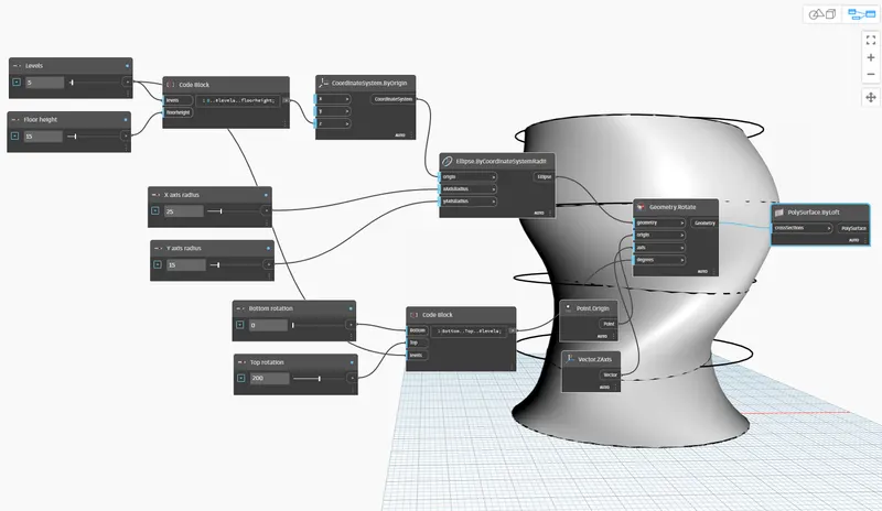
Result:
A parametric stadium is developed by using dynamo.