Creating Conceptual mass in REVIT and Creation of Sinusoidal curve and a Parametric stadium using Dynamo
1) Using Dynamo create a set of sinusoidal points and create a curve and create a surface out of the curve.
AIM
To draw the curve by using a set of sinusoidal points and create a surface.
INTRODUCTION
Dynamo is a visual programming software. Nowadays we are in need of the dynamo because in the construction industry or the project oriented industries are moving towards the artificial intelligence or towards the machine learning. Dynamo also enhance the project process and workflow. Nowadays people are leaning towards the dynamo in order to improve their work process and enhances the project process. It is a visual programming tool that helps in expressions we can arrange graphics, texts as a part of its syntax secondary notation. Instead of creating the program textually, this programming language allows the user to manipulate the graphical elements in an interactive manner. In dynamo we will be learning about the certain keywords like wire, nodes, input, output etc.
PROCEDURE
Open new Revit file
Go to Manage> Dynamo
Open Dynamo
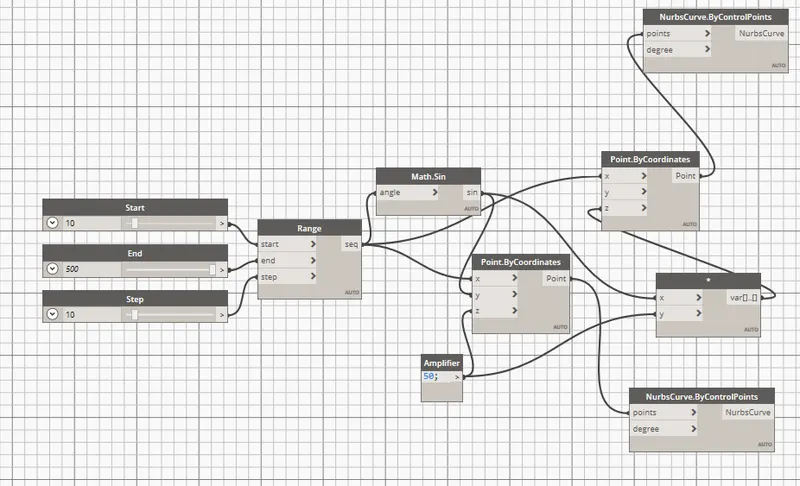
Go to search box in dynamo file and search POINT BY CO-ORDINATES and RANGE.
Now search INTEGER SLIDER in the search box and load three INTEGER SLIDERS.
Rename the INTEGER SLIDER as start, end and step.
Give them the input values as 10, 500 and 10 to start, end and step respectively.
Now join those 3 INTEGER SLIDER to 3 respective components of RANGE.
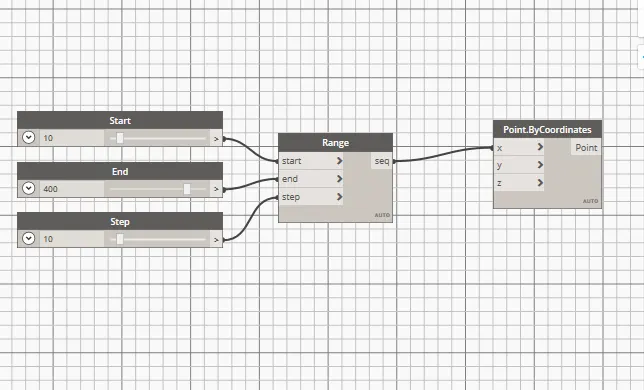
Join RANGE to the POINT BY COORDINATE.
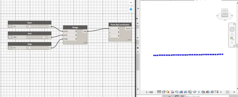
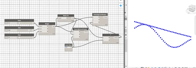
Now load MATH.SIN factor and a code block.
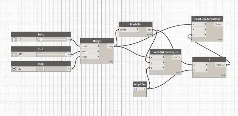
Rename that code block as AMPLIFIER and fix the value of that as 50.
Now load another POINT BY COORDINATE
Assign POINT BY COORDINATE with RANGE, MATH.SIN, and AMPLIFIER as X, Y, and z resp.
Load the PRODUCT factor and assign X, Y components to that product.
Now join SINE and AMPLIFIER to PRODUCT.
Join PRODUCT to POINT BY COORDINATE
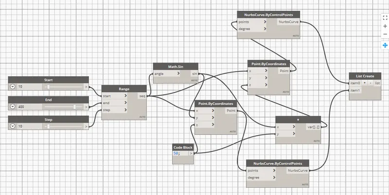
Load NURBS BY CONTROL POINT
Make another copy
Join the POINT BY COORDINATE to each NURB
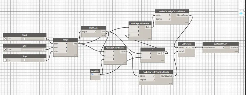
Load LIST
Add another item and assign it with NURBS individually
Load SURFACE BY LOFT
Assign the list to the SURFACE.
RESULTS
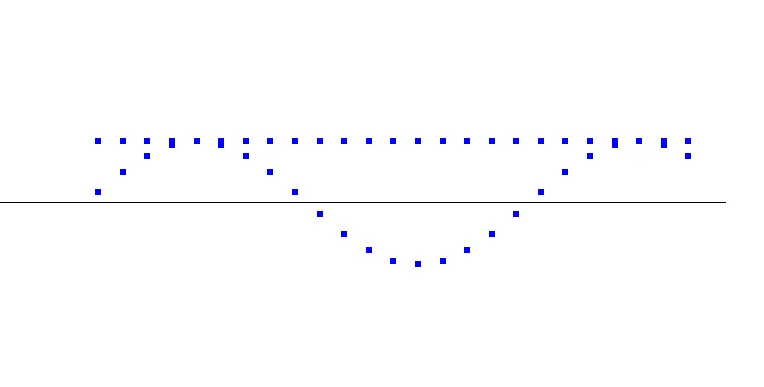
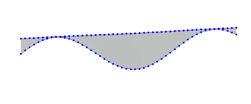
SINUSOIDAL POINTS
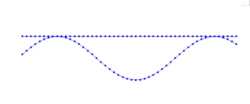
SINUSOIDAL CURVE
SINUSOIDAL SURFACE
2) Create a conceptual layout of floor plan in Dynamo. Using the tools available in dynamo. Link the lines to appropriate model elements in Revit by choosing the wall types and wall parameters. Make use of the sliders to slide through the height of the wall and length of the wall.
AIM
To create a conceptual layout of floor plan in dynamo.
PROCEDURE
Open new Revit file
Go to Manage> Dynamo
Open Dynamo
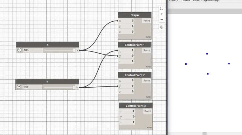
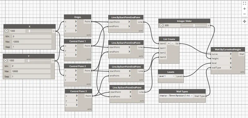
In the library type points and select 4 times POINTS BY COORDINATE and rename it as (Origin, Control Point 1, Control Point 2, and Control Point 3)
Load INTEGER SLIDER and insert 2 times and rename it to X and Y.
Select the X and connect to X in control point 1 and control point 3.
Select the Y and connect Y in control point 2 and control point 3.
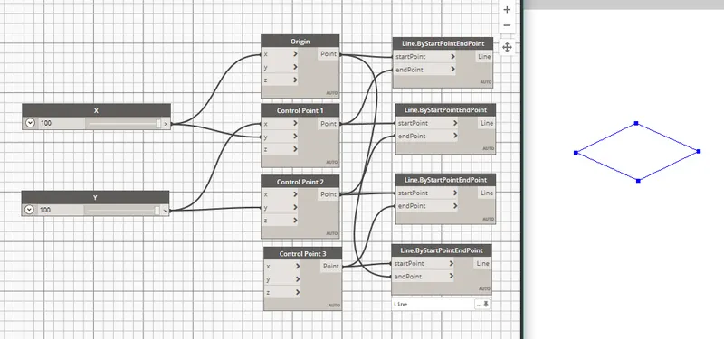
Type Line and select by start end point and insert 4 times and arrange them.
Connect the origin point to start point of 1st and 2nd.
Connect the control point 1 to end point of 1st and 4th.
Connect the control point 2 to end point of 2nd and start point of 3rd.
Connect the control point 3 to end point of 3rd and start point of 4th.
Type list and select create list and make it as 4 and connect all the lines to item 0 to item 3.
Type wall type by curve and select that.
Type wall type and insert. Type level and insert.
Type slider and insert and rename it to height of wall.
Connect the list to curve (wall by curve).
Connect wall type to wall type in (wall by curve and height).
Connect level to level in wall by curve and height.
Connect the slider height of wall to height in wall by curve and height.
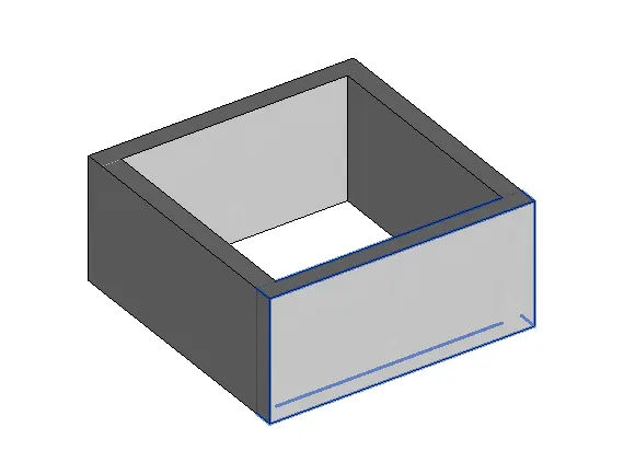
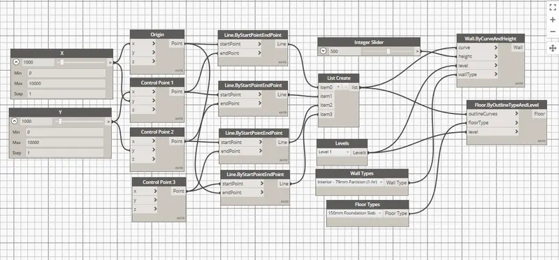
Load floor type and select the type of floor
Load floor by outline type and level
Assign curve, floor type and level
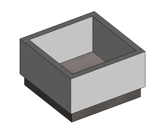
RESULTS
LAYOUT OF WALL
LAYOUT OF FLOOR
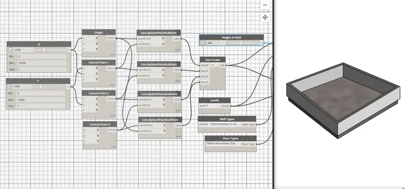
We can change the wall height using slider.
3) Create an array of model elements in Revit. Use dynamo to vary the properties of model elements by using the slider or code block
AIM
To create array of model elements in Revit and vary the properties of model elements by using sliders or code block
PROCEDURE
Open new Revit file
Open a new Architectural template.
Go to the Architectural tab > Columns
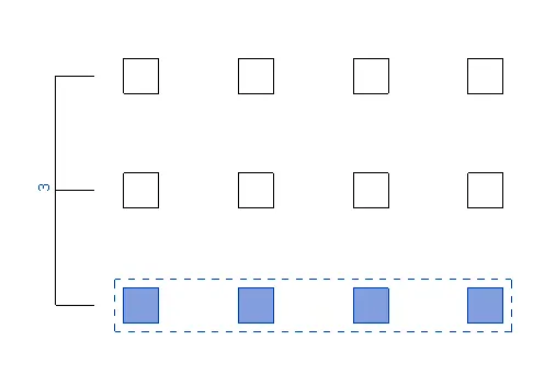
Select the column and type AR to enter array command
Specify the number of columns and the distance at create array.
Adjust the array settings and finish up with the array of model elements creation.
Go to Manage> Dynamo
Open Dynamo
Load select elements.
Load Rotation.
Load integer slider.
Select the model elements and select the columns in the Revit.
Join the elements to family instances.
Join number slider to degree.
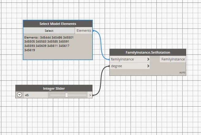
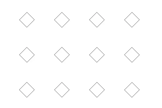
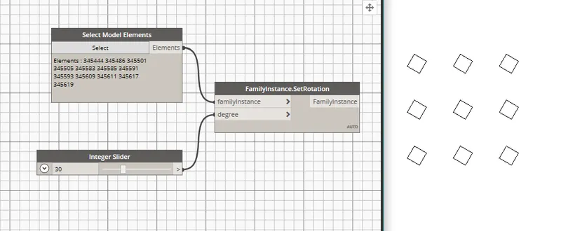
We can adjust colun rotatioon usiing slider.
4) Create a conceptual mass in Revit and develop a parametric column by dividing the surfaces and apply the concepts similar to use in parametric walkway modelling. Use triangular bent or square shaped panels to add finish to the parametric column
AIM
Using dynamo create a conceptual mass in Revit and develop a parametric column by dividing the surfaces and apply the concepts similar to use in parametric walkway modelling. Use triangular bent or square shaped panels to add finish to the parametric column.
PROCEDURE
Open conceptual mass
Draw the shape
Settings plane and shape
Open a new family in Revit and select conceptual mass
Create a level of 3000 from the base level in the elevation view and rename it
Select the floor plan view and set the workplane select the spline through points and draw the spline path
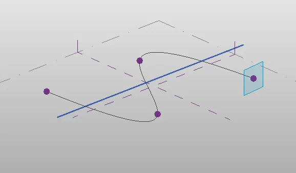
Select the control point and set the reference and select show
Provide circumscribed polygon of size 3000
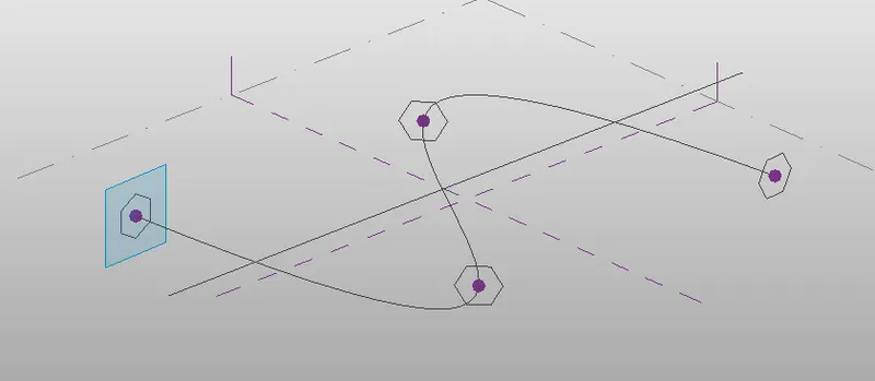
Select the plane of all the control points and select the line and click on create form
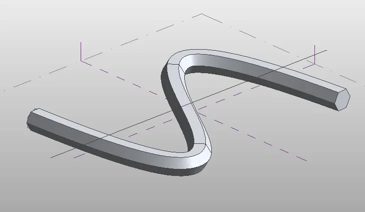
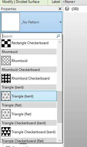
Select the components and select the filter and select the form and select divide surface
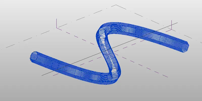
Select the pattern as triangle bent
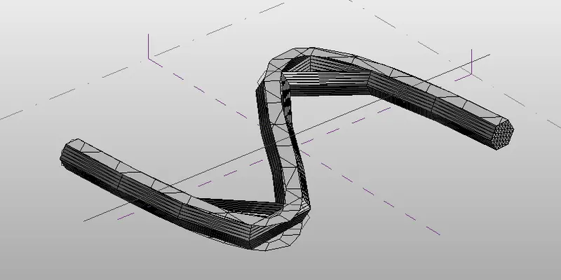
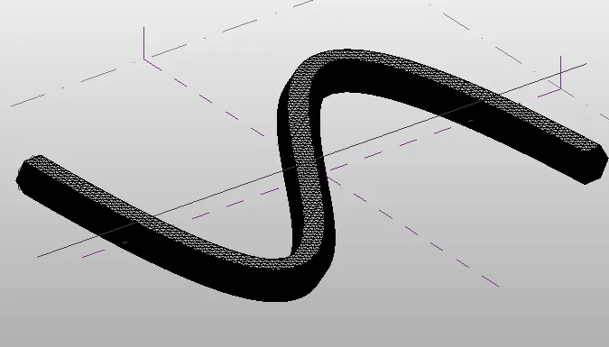
Increase the number in the grids for smooth surface
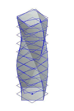
5) Use Dynamo to work on developing a Parametric Stadium. List your parameters and use the visual programming approach to complete the modelling, you can use the concepts discussed in parametric high rise tower in class for reference.
AIM
Using dynamo work on developing a Parametric Stadium. List your parameters and use the visual programming approach to complete the modelling, you can use the concepts discussed in parametric high rise tower in class for reference.
PROCEDURE
Open new Revit file
Go to Manage> Dynamo
Open Dynamo
After selecting dynamo
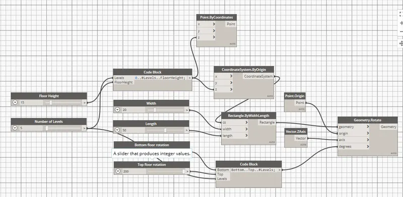
In the dynamo screen type slider and insert 4 slider and rename it
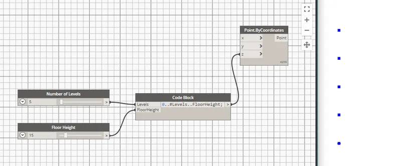
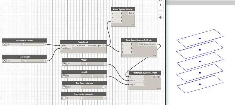
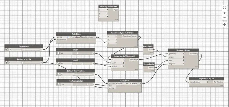
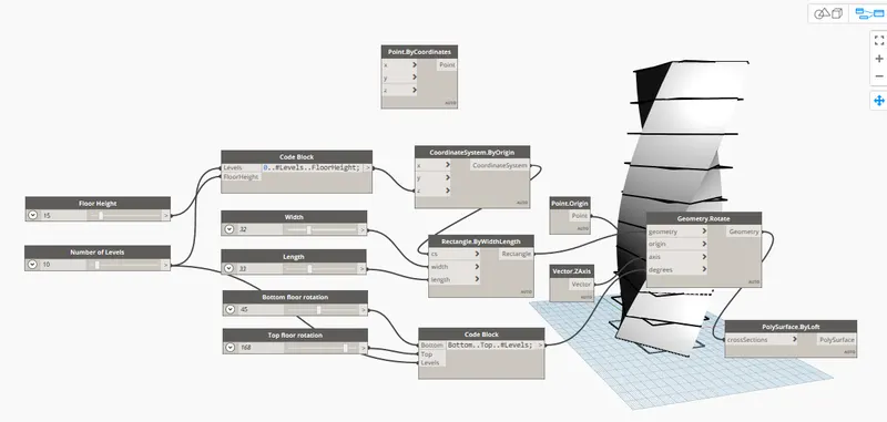
Type points and select points by coordinate to create floor Type code block (0.#levels. Floorheight)
Join levels and floor height
Type coordinate system by origin and join the code block to it in z Type code block (bottom top #levels)
Join the bottom rotation top rotation and no of floor respectively
Type rectangle by width
Type slider and rename it as width/length of rec
Join the coordinate to cs
and slider to width and length
Type rotate and insert geometry rotate
Type origin and inset point origin
Type z axis and insert
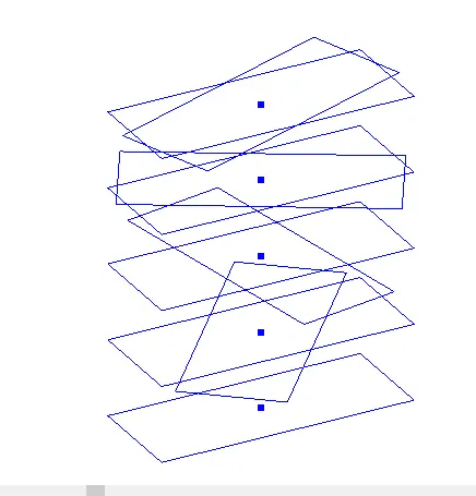
Join rectangle to geometry point to origin and degrees to code book [bottom.top. #levels)
Type poly surface by loft and insert
Join geometry to cross section