Creating Conceptual mass in REVIT and Creation of Sinusoidal curve and a Parametric stadium using Dynamo
Aim:
1. To create a set of sinusoidal points, a curve and a surface out of the curve using dynamo.
Introduction:
- Dynamo is an open source visual programming language for Revit, written by designers and construction professionals. Its a programminglanguage that allows you to type lines of code; while also creating an algorithm that consist of nodes.
- Using dynamo work can be carried out with enhanced BIM capabiilities in Revit.Dynamo and Revit an together be utilized to model and analyze complex geometries, automate repetative processes,minimize human error and export data to exer and other file types.Dynamo can make the design process more efficient with an intuitive interface and many pre made scripting libraries availabe as well.
- Conceptual mass of a building contains different types of parameters like level, floor area, floor perimeter and architect can generate early quanties takeoff from the mass. In Bim modelling services the conceptual mass of a building can be exported to to any other format for performing early energy analysis.
Procedure:
- Initially, open the architecture template of Revit software and go to manage tab.
In manage tab select the dynamo.
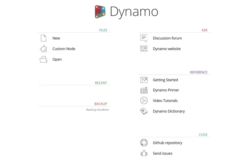
Then dynamo window opens and then go to new option.

STEp-2:-
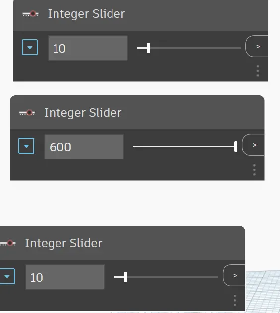
- write the command and type integer slider
- give start, end and step values
STEp-3:-
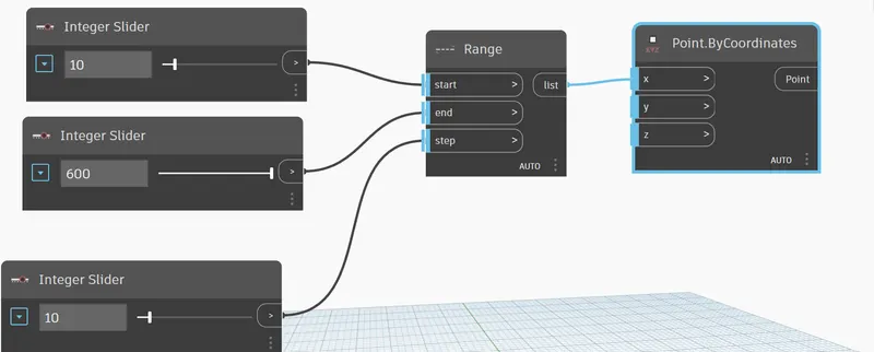
- Now give a command range
- where u can connect start ,end amd step
- connect it with pouint with coorrdinates in onnly x dircetion
STEp-4:-
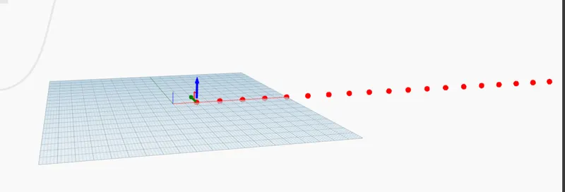
- WE can see the coordinates in x direction with a given step value
STEp-5:-
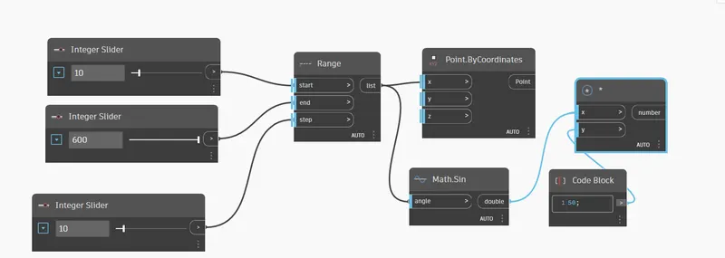
- now give sin value
- command is math.sin and amplify it by 50 times
- multily both values and result iis connected with point coordinatews in z direction
STEP-6:-
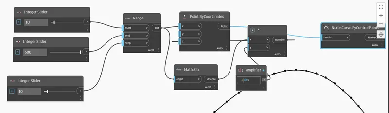
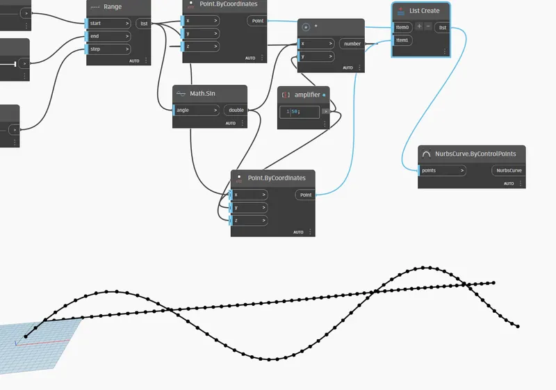
- USE command nurbcommand to pass lines through the points
STEp-7:-
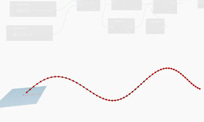
- WEcan see that lines are passing through the points
STEP-8:-
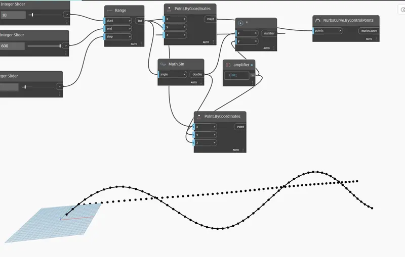
- ADD another point by coordinates and connect it with the range
- math.sin is connected with z coordinates
- amplifier is connected with y cordinates
STEp-9 :-
- curve can be seen with with both lines passsing through it
STEp-10 :-
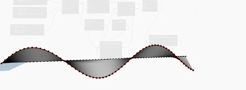
- ADD surface by loft and connect both curves throgh it
Result:
A set of sinusoidal points have been created as follows:
2.Create a conceptual layout of floor plan in dynamo . Using the tools available in dynamo link the lines to appropriate model elements in Revit by choosing the wall types and wall parameters. Make use of the sliders to slide through the height of the wall and length of the wall.
Aim:
To create a conceptual layout of a floor plan in dynamo.
Procedure:
step-1:-
Open a new architectural template.
Go to manage tab and open the dynamo --> New.
step-2:-
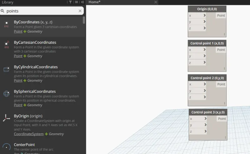
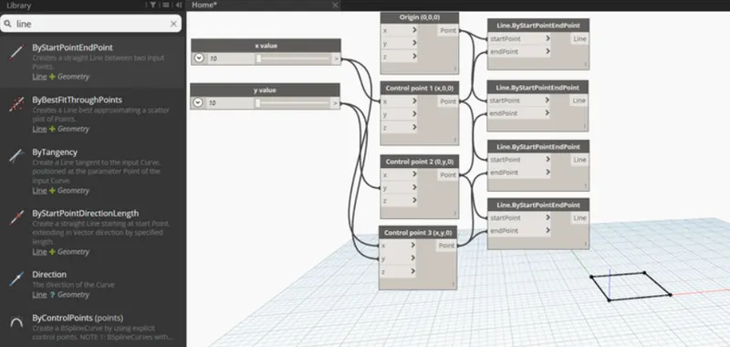
Inorder to create the wall first we have to create four control points.
For this, search points by coordinates in the search panel of the library.
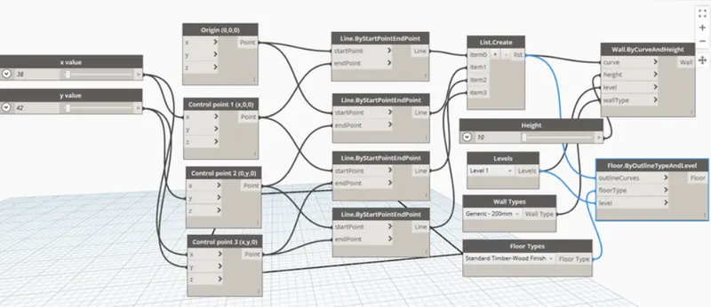
1st one is named as origin (0,0,0) and the rest is named as control point 1(x,0,0), control point 2(0,y,0) and control point 3(x,y,0).
step-3:-
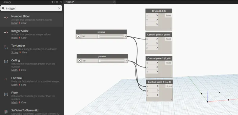
Now, provide two integer sliders to provide the values for x and y.
step-4:-
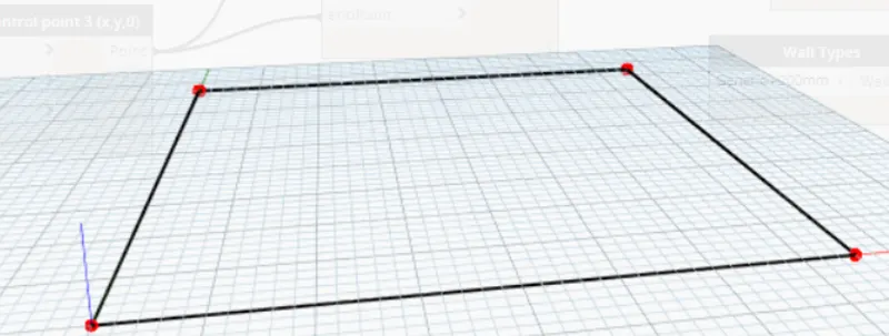
Now, we have to connect these points by a line.
So for this, search line by start and end point and insert 4 blocks.
The input for these blocks are the points created previously.
step-5:-
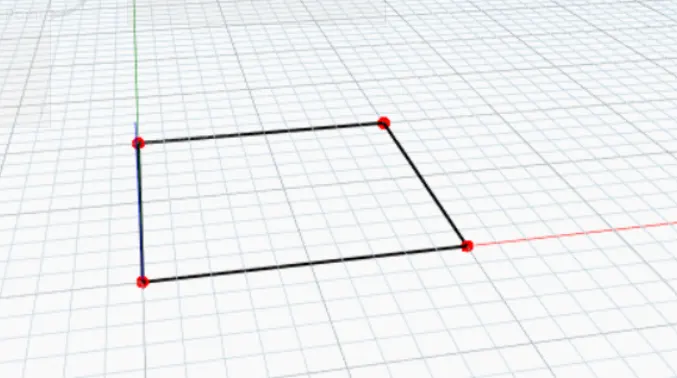
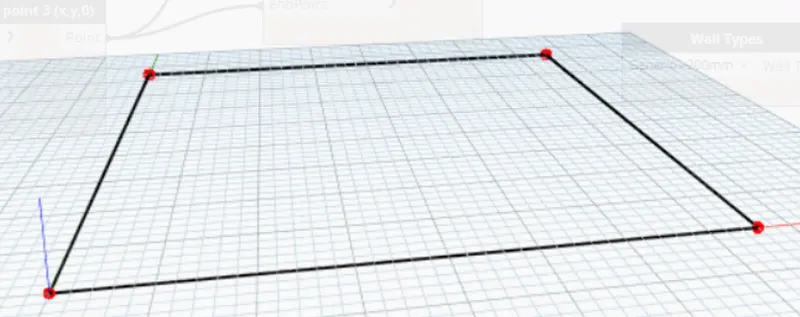
Hence, the layout of the floor plan is obtained.
step-6:-
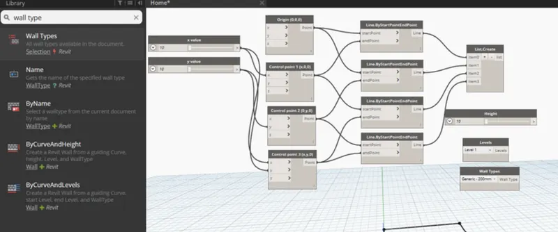
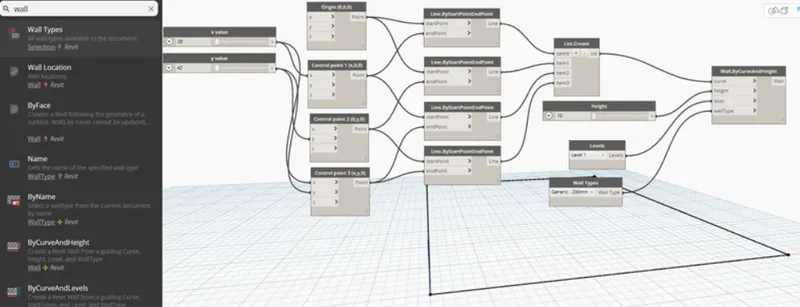
Now, search wall in the panel and choose wall by curve and height.
So, for this input required are curve, height, level and wall type. Inputs are given as follows:
For curve, combine all the four lines in a list by choosing list.create.
For height, another number slider is chosen and name it as height.
For level, search level in the search panel it will contain the levels availbale in your revit folder. Then choose the level in which you want to place your structure.
For wall type, search wall type in the panel and it will display the wall types linked in the revit file.
step-7:-
The floor plan layout is given below:
STEP-8:-
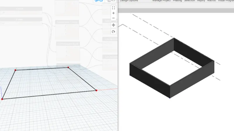
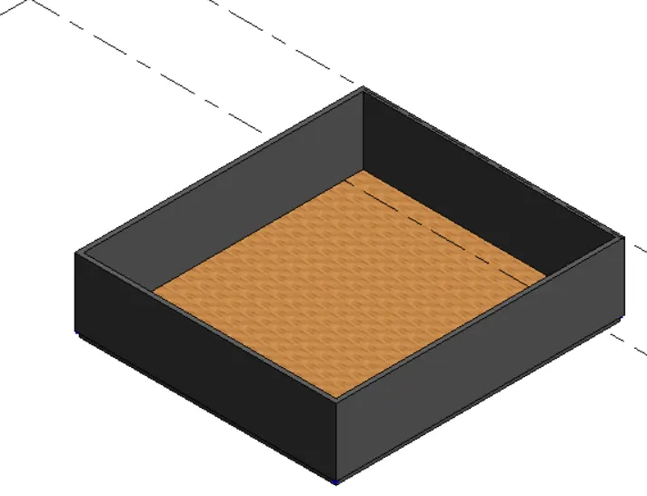
Now, go to revit file to view the 3D form where the height of the wall is visible.
STEP-9:-
The height of the wall can be adjusted using the slider.
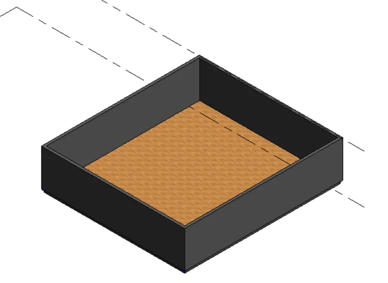
Now, we have to place the floor.
For this, type floor in the library and select floor by outlinecurve, floor type and level.
This can be viewed in 3D view in revit file.
Result:
Hence the conceptual floor plan layout has been developed and is as follows:
3.Create an array of model elements in Revit. Use dynamo to vary the properties of model elements by using the slider or code block
Aim:
To create an array of model elements in revit.
Procedure:
Open a new architectural template in revit file.
In that go to architecture tab --> Columns --> Architectural column --> Place the column (610mmx610mm).
Now, similarly 4 columns are created.
STEp-2;-
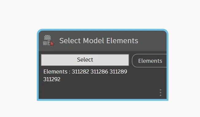
- in command box type select model elements
- select it from revit
STEp-3:-
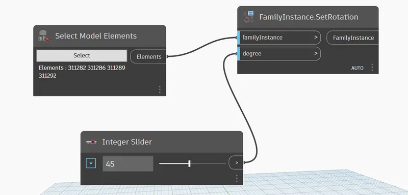
- SELECT family instance rotation
- ALso use integer slider and give it 45
- so that it becomes degree of 45
STEP-4:-
- WE can see that it is rotated by 45 degrees

Result:
The array of model elements have been created and their properties are being varied through the blocks created in dynamo
4.Create a conceptual mass in Revit and develop a parametric column by dividing the surfaces and apply the concepts similar to used in parametric walkway modelling. Use triangular bent or square shaped panels to add finish to the parametric column
Aim:
To create a conceptual mass in Revit and develop a parametric column by dividing the surfaces.
Procedure:
STEP-1:-
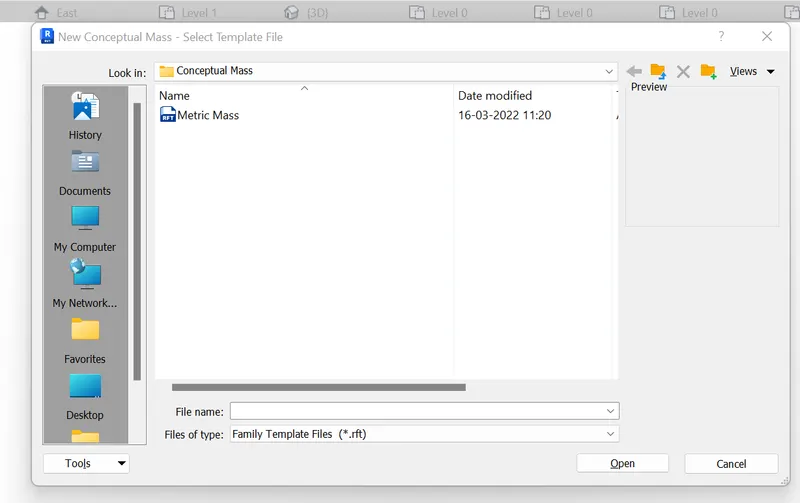
- go to new and open conceptual mass
- go to metric mass in that
STEp-2:-
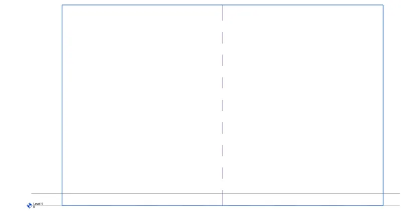
- AFTER opening that go to elevation
- SET the level plane
- SET the level 12' as that would be the height of roof
STEP3:-
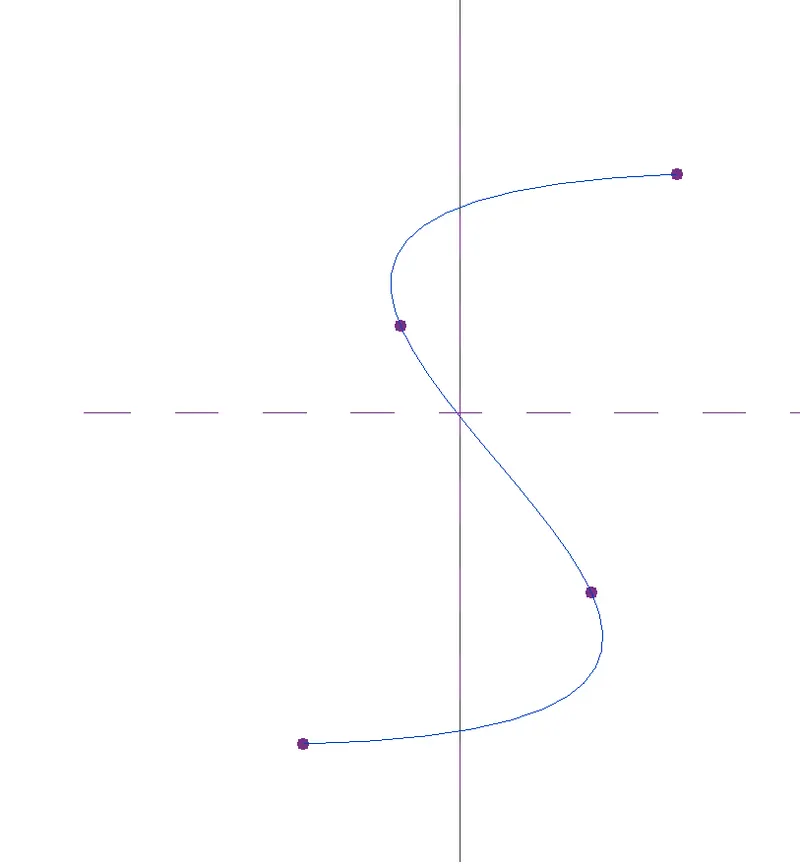
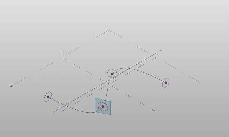
- now go to create model elements
- use spline curve in that
STEp-4:-
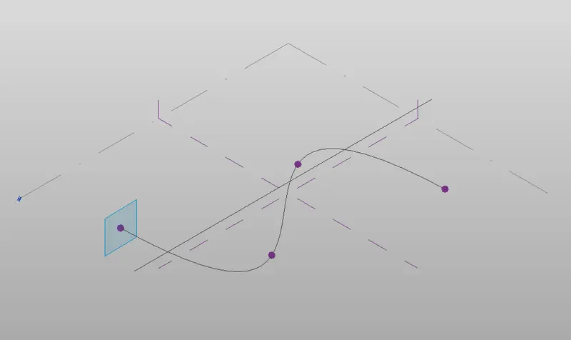
- GO to 3d view
- now set the work plane in every node
STEp-5:-
- After setting work plane in every node
- now create a circumscribed polygon in every node

STEp-6
- CIRcumscibed polygon is created of 12'
- Because that will be our height of roof
STEp-7:-
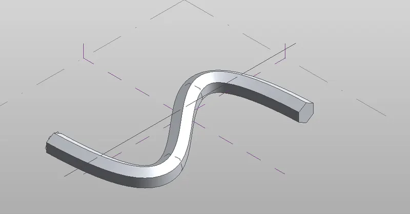
- NOw create form
- SELEct the curve and its entrance
- figure of walkaway is created
STEp-8:-
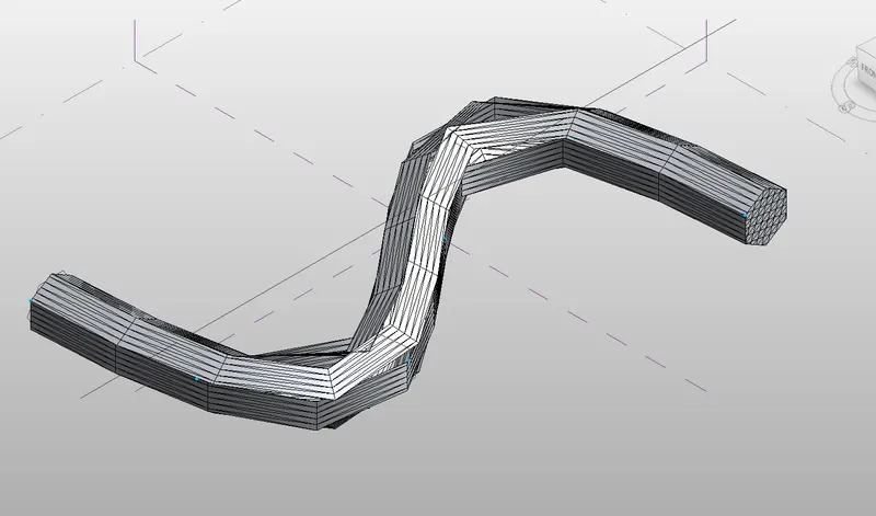
- now go to filter and untick everything except forms
- now divide the surface
- go to properties and select triangle bend
RESULT:-
5.Use Dynamo to work on developing a Parametric Stadium. List your parameters and use the visual programming approach to complete the modelling, You can use the concepts discussed in parametric high rise tower in class for reference.
Aim:
To develop a Parametric Stadium using dynamo in Revit.
Procedure:
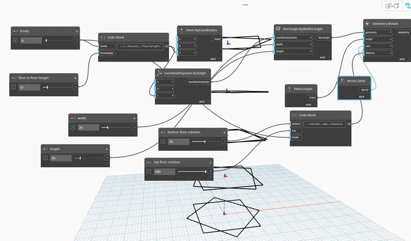
STEp-1:-
- GO to command box
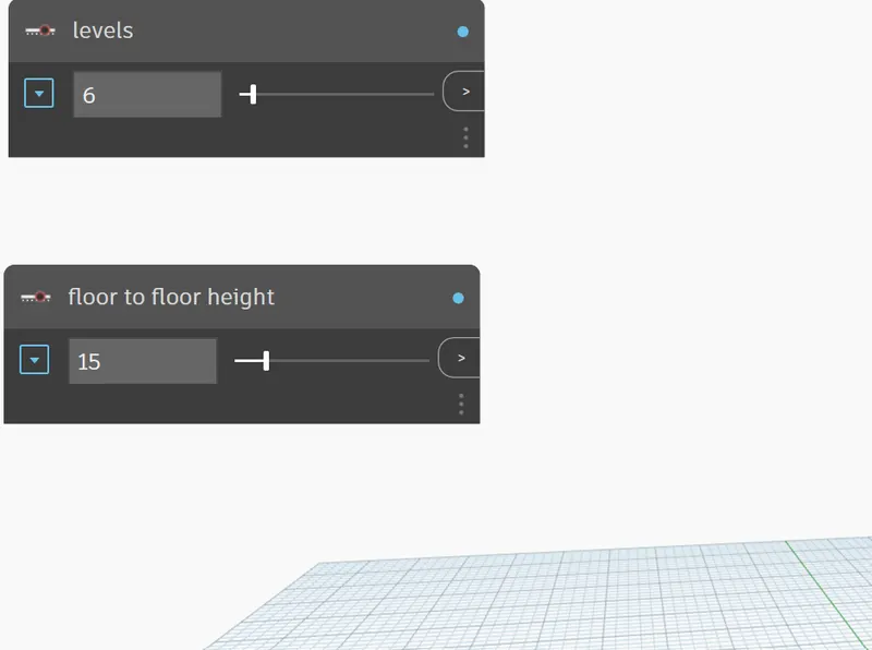
- now use integer slider
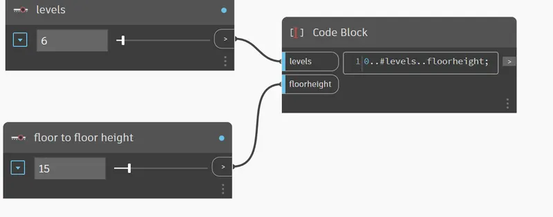
- now change its name to levels and and floor to floor height
- make levles 6 and floor height to 15
STEp-2:-
- draw a code block
- write a code 0..#levels..floorheight and connect it with levels and floor height
STEP-3:-
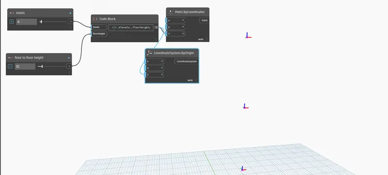
- use command point by corrdinates
- now use command by origin
- connect the written code with z axis of both
STEP-4:-
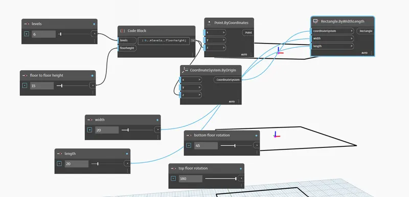
- Now make a code block
- draw bottom floor rotation and top floor rotation
- also make a code block and give width and length
STEp-5:-
- USE a command and use rectangle by width and length
- connect it with this recatngle
STEP-6:-
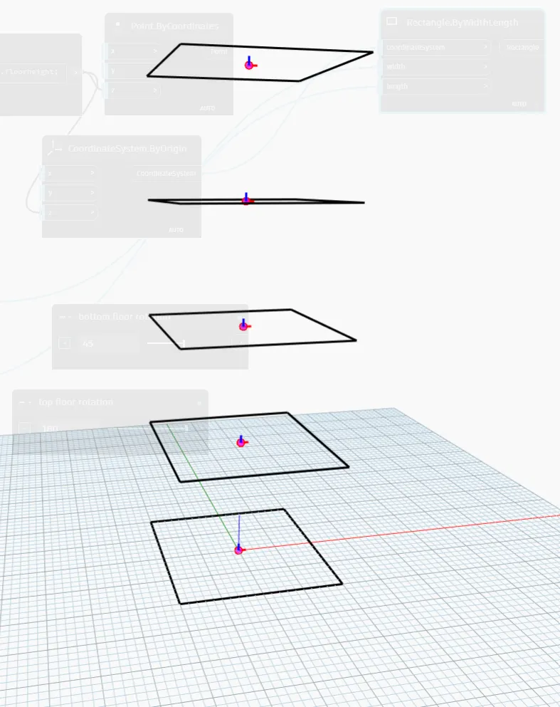
- now we have to rotate it
- use command point origin and vector z axis
- make a code block of geometery rotate and connect it with
STEP-7:-
- GIve bottom floor rotation as 45 and top rotationas 180
- write a code bottom..top ..#levels
- connect it with geometery rotate block
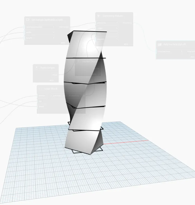
RESULT:-