Creating Conceptual mass in REVIT and Creation of Sinusoidal curve and a Parametric stadium using Dynamo
1Q]
AIM: -
Create a set of Sinusoidal points using Dynamo
Create a Curve
Create a Surface out of the curve.
PROCEDURE: -
Open Architectural Template in Revit
Click on MANAGE TAB
Go to Visual Programming panel
Select Dynamo

Dynamo app opens
In the Home page click on New
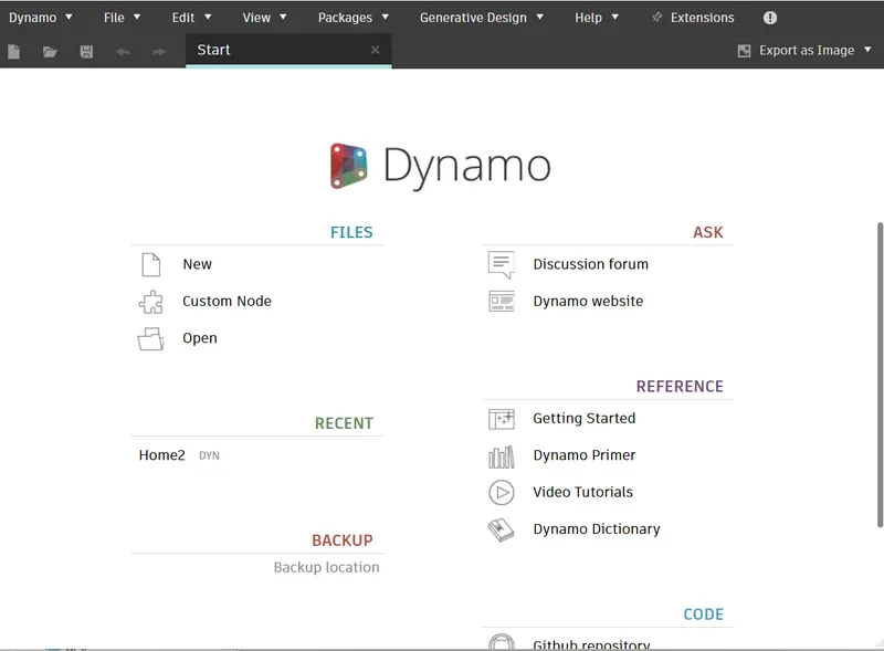
New Home page opens
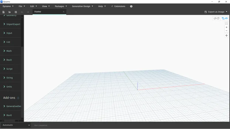
Now, we have to Insert Integer slider
For this, Go to Library
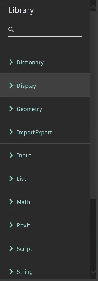
Type Integer slider
Click on the Integer Slider from the dropdown list
Integer slider block appears in the model space
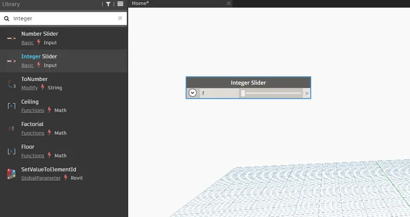
Place 3 Integer Sliders on the model space for making Sinusoidal points.
Double click on the Integer Slider block
Now, Edit the name: START
Now, Edit the name: END
Now, Edit the name: STEP
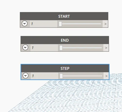
Change minimum, maximum and step values if required for the Integer slider
Type Range in the Library
Place the Range block in the mode space.
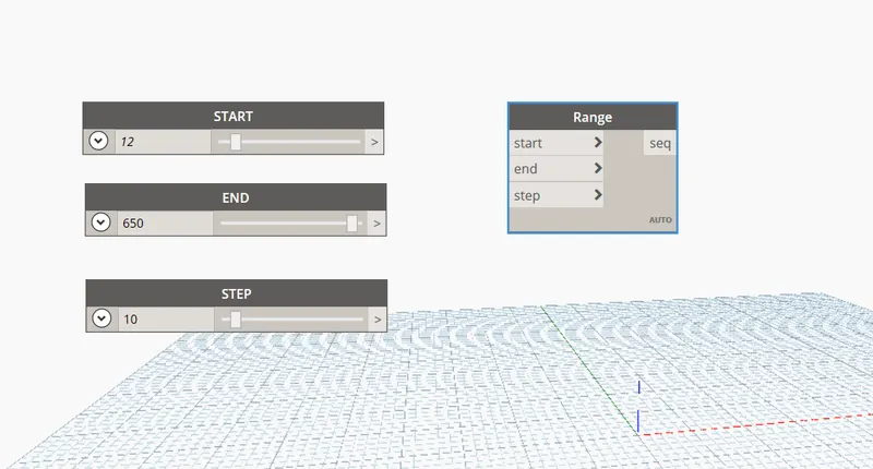
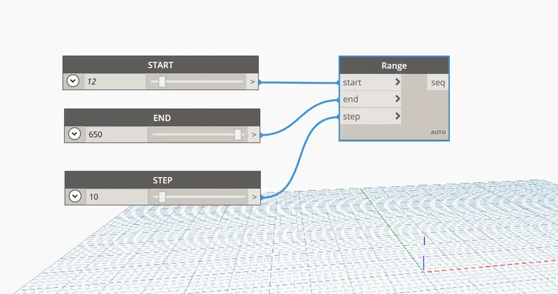
Connect the 3 Integer sliders to the Range
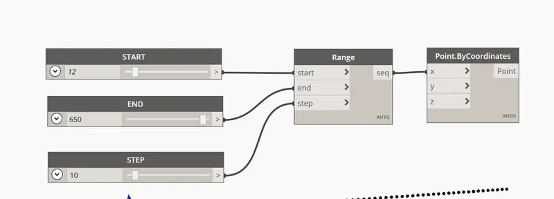
Type Point.bycoordinate in the Library
We require 2 blocks
Place 2 Point.bycoordinate blocks in the mode space.
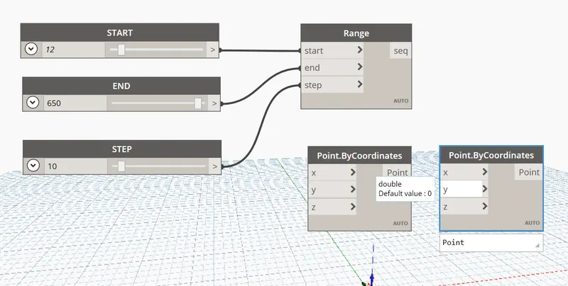
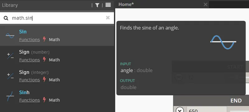
Type Math.sin in the Library
Place Math.sin block in the mode space.
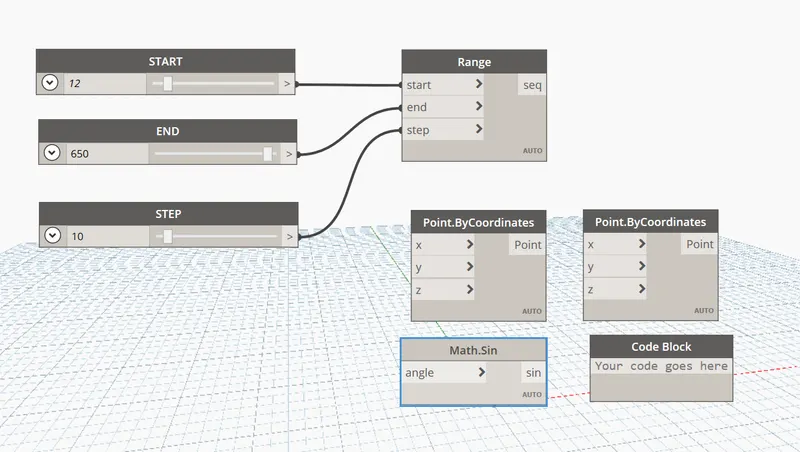
Type code block in the Library
Place code block box in the mode space.
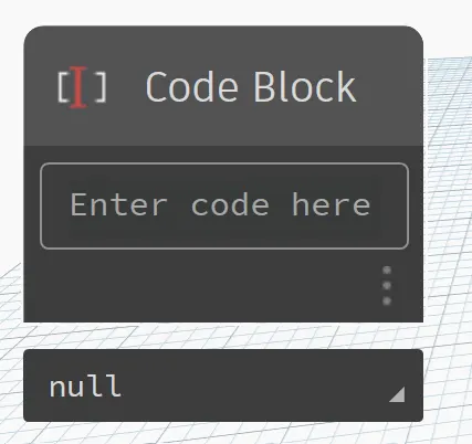
Type 50 value in the Code block
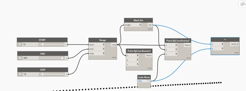
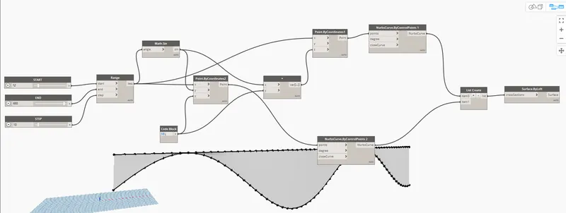
Connect seq in Range block to “X” in Point.bycoordinate 1 block
Connect seq in Range block to “X” in Point.bycoordinate 2 block
Connect seq in Range block to “Angle” in Math.sin block
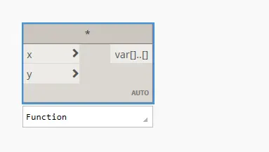
Type Product in the Library
Place the operator in the model space.
Connect Code block to Point.bycoordinate 2 block to “Z” value
Connect sin in Math.sin block to Point.bycoordinate 2 block to Y value
Connect sin in Math.sin block to Product operator block to X value
Connect Code block to Product operator block to “Y” value
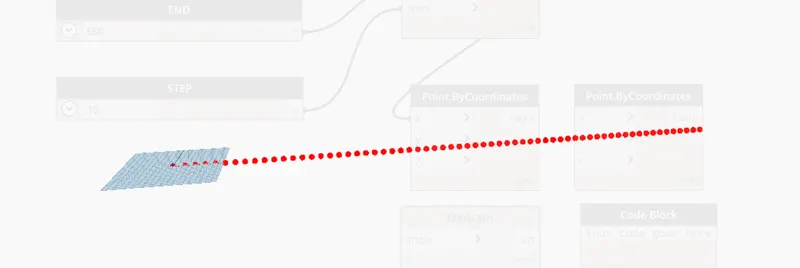
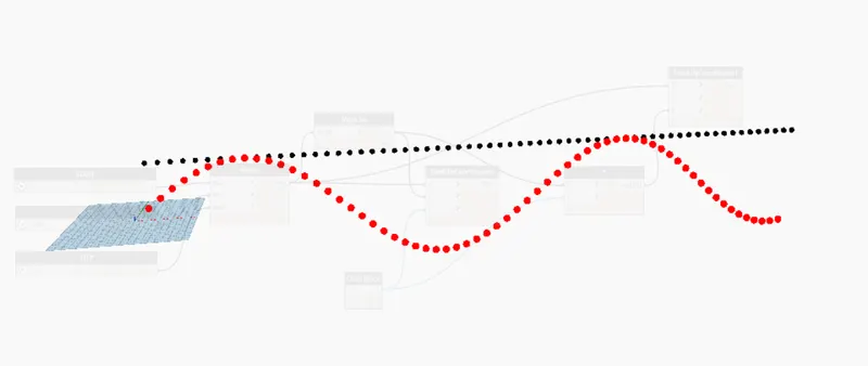
Points are created
Type NURBS in the Library
Place 2 BYCONTROL POINTS (DEGREE, POINTS, CLOSECURVE) in the model space.
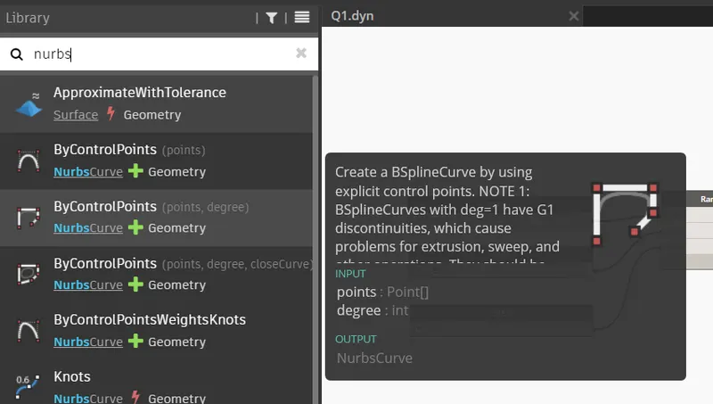
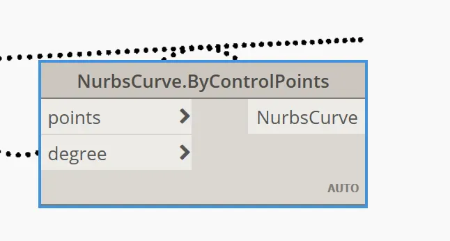
Connect points in Point.bycoordinate 1 to points in Nurbscurve.ByControlPoints 1block
Connect points in Point.bycoordinate 2 to points in Nurbscurve.ByControlPoints 2 block
Type List create in the library
Place it in the model space
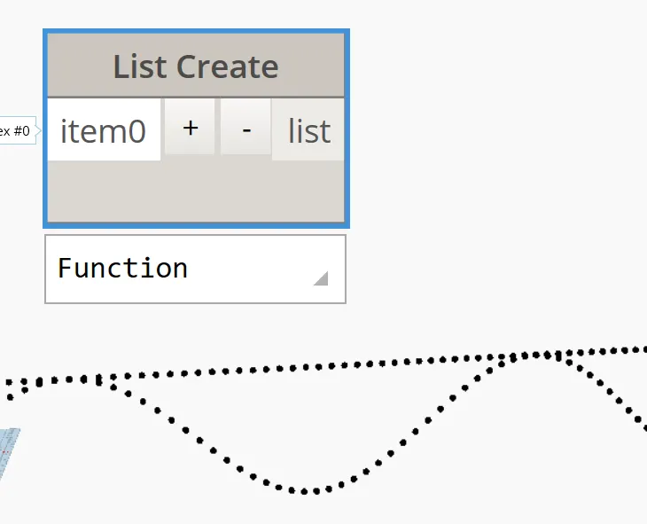
Create item 1 in the List block by clicking on + symbol
Connect NurbsCurve in Nurbscurve.ByControlPoints 1 block to Item 0 in List create block
Connect NurbsCurve in Nurbscurve.ByControlPoints 2 block to Item 1 in List create block
Curve is created.
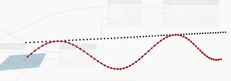
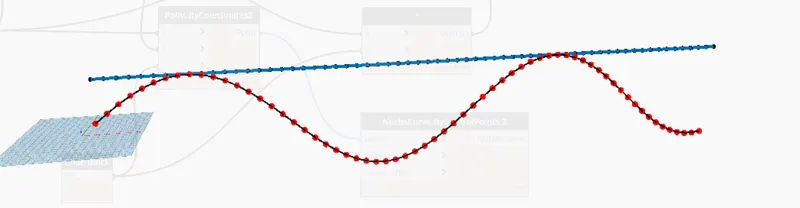
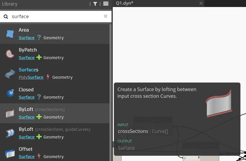
Type Surface
Select ByLoft( crosssection) option from the list
Place it in the space
Connect List in the List create block to Crosssections in Surface,ByLoft block.
Surface is created
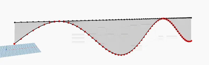
RESULT: -
We created a set of Sinusoidal points using Dynamo
Created a Curve
Created a Surface out of the curve.
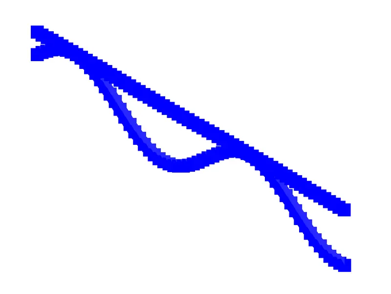
Cross-checked in Revit.
2Q]
AIM: -
Create Conceptual Layout of Floor Plan in Dynamo
Link the lines to appropriate model elements in Revit by choosing the Wall types and Wall parameters.
Make use of sliders to slide through the height and Length of the wall.
PROCEDURE: -
Open Architectural Template in Revit
Click on MANAGE TAB
Go to Visual Programming panel
Select Dynamo
Dynamo app opens
In the Home page click on New
New Home page opens
Now, we have to Insert Integer slider
For this, Go to Library
Type Integer slider
Click on the Integer Slider from the dropdown list
Integer slider block appears in the model space
Place 2 Integer Sliders on the model space
Type POINTS
Click on the ByCoordinates (x,y,z) from the dropdown list
Place 4 ByCoordinates (x,y,z) blocks on the model space
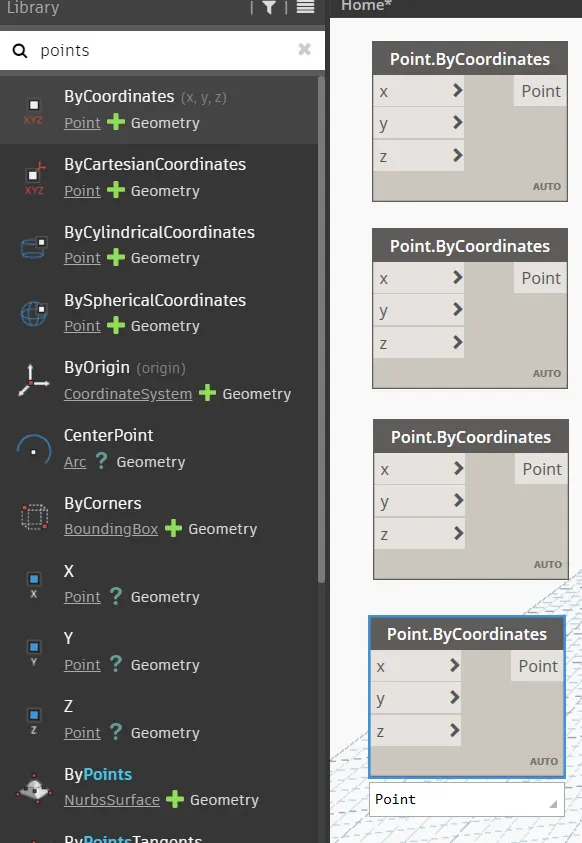
Wall has 4 sides so we need 4 ByCoordinates (x,y,z) blocks
Connect Integer Slider-1 to X in Points.ByCoordinates-1 block
Connect Integer Slider-1 to Y in Points.ByCoordinates-2 block
Connect Integer Slider-2 to X in Points.ByCoordinates-2 block
Connect Integer Slider-2 to Y in Points.ByCoordinates-3 block
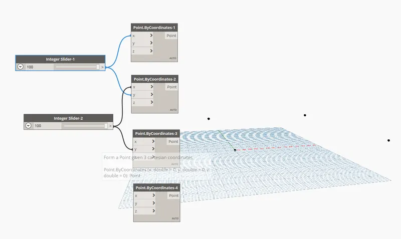
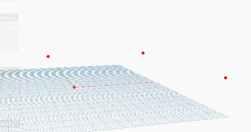
We created points
Now, we need to create Lines
Type LINE in Library
Click on the ByStartPointEndPoint from the dropdown list
Place 4 Line.ByStartPointEndPoint blocks on the model space

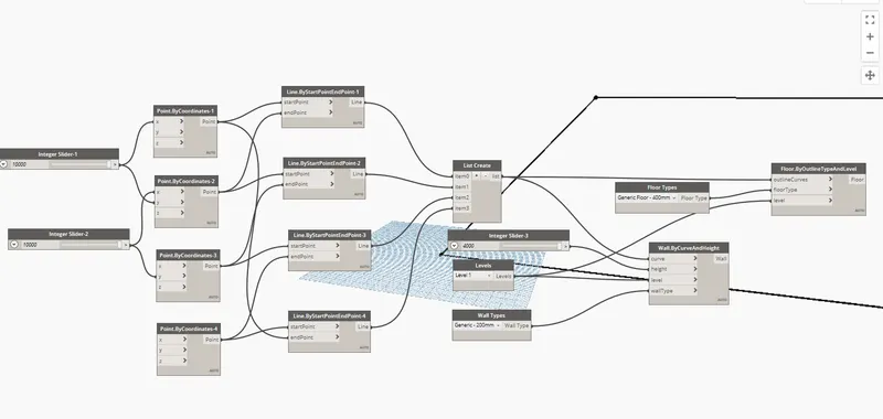
Connect point in Points.ByCoordinates-1 block to StartPoint in Line.ByStartPointEndPoint-1
Connect point in Points.ByCoordinates-2 block to EndPoint in Line.ByStartPointEndPoint-1
Connect point in Points.ByCoordinates-2 block to StartPoint in Line.ByStartPointEndPoint-2
Connect point in Points.ByCoordinates-3 block to EndPoint in Line.ByStartPointEndPoint-2
Connect point in Points.ByCoordinates-3 block to StartPoint in Line.ByStartPointEndPoint-3
Connect point in Points.ByCoordinates-4 block to EndPoint in Line.ByStartPointEndPoint-3
Connect point in Points.ByCoordinates-4 block to StartPoint in Line.ByStartPointEndPoint-4
Connect point in Points.ByCoordinates-1 block to EndPoint in Line.ByStartPointEndPoint-4
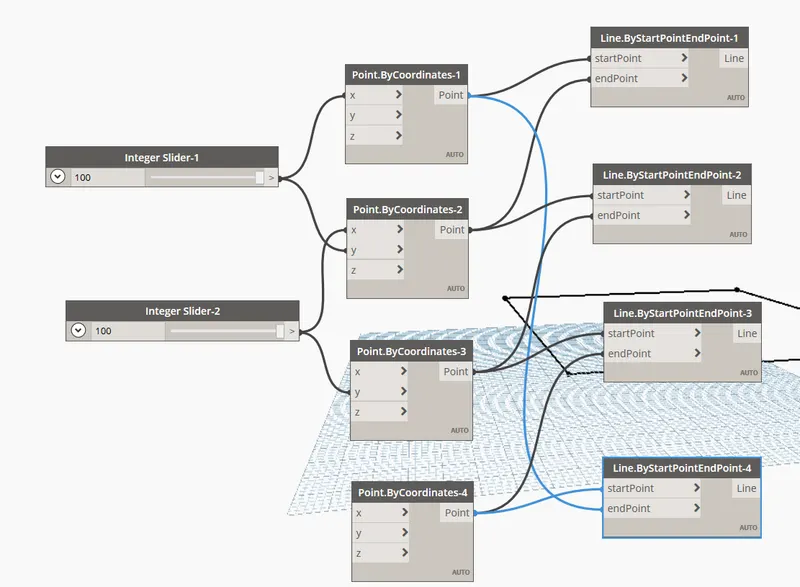
To create complete WALL, connect the lines to LIST CREATE block
Type List create in the library
Place it in the model space
Create item 1 in the List block by clicking on + symbol
Create item 2 in the List block by clicking on + symbol
Create item 3 in the List block by clicking on + symbol
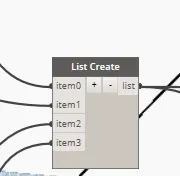
Connect Line in Line.ByStartPointEndPoint-1 block to Item-0 in List Create block
Connect Line in Line.ByStartPointEndPoint-2 block to Item-1 in List Create block
Connect Line in Line.ByStartPointEndPoint-3 block to Item-2 in List Create block
Connect Line in Line.ByStartPointEndPoint-4 block to Item-3 in List Create block
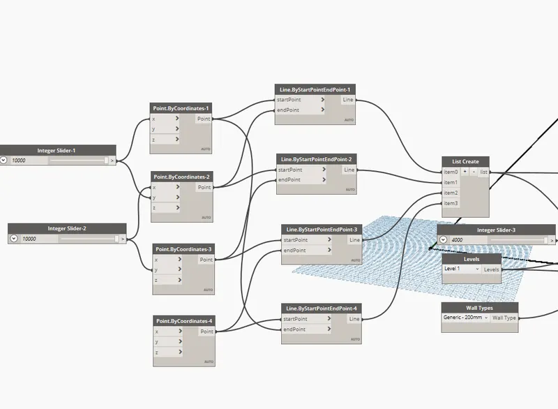
Now, we have to set Levels, Wall Height and Floor
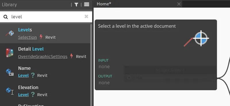
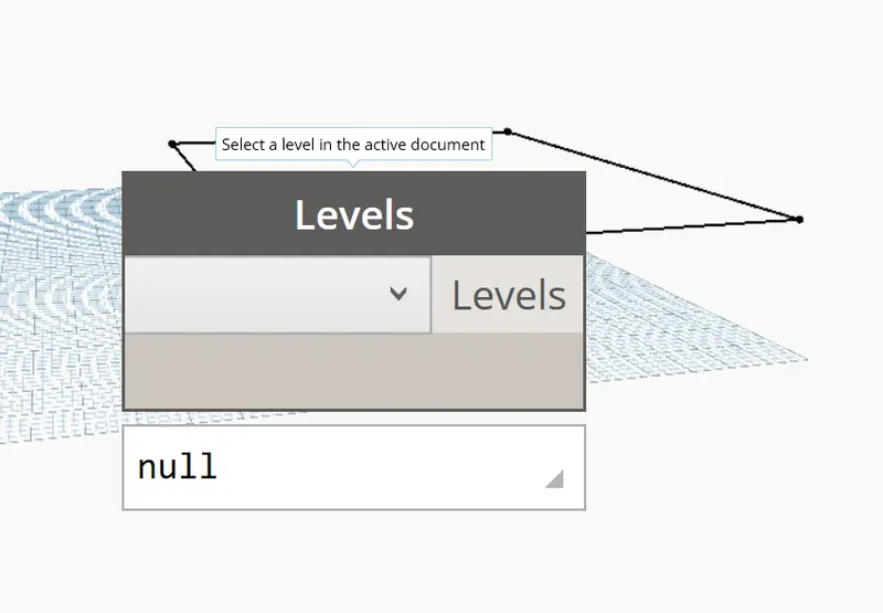
Type Levels in Library
Place Levels block in the model space
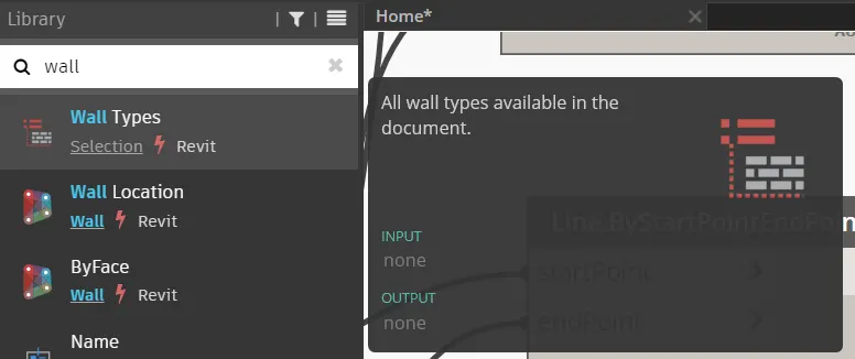
Type Wall Type in Library
Place Wall Types block in the model space
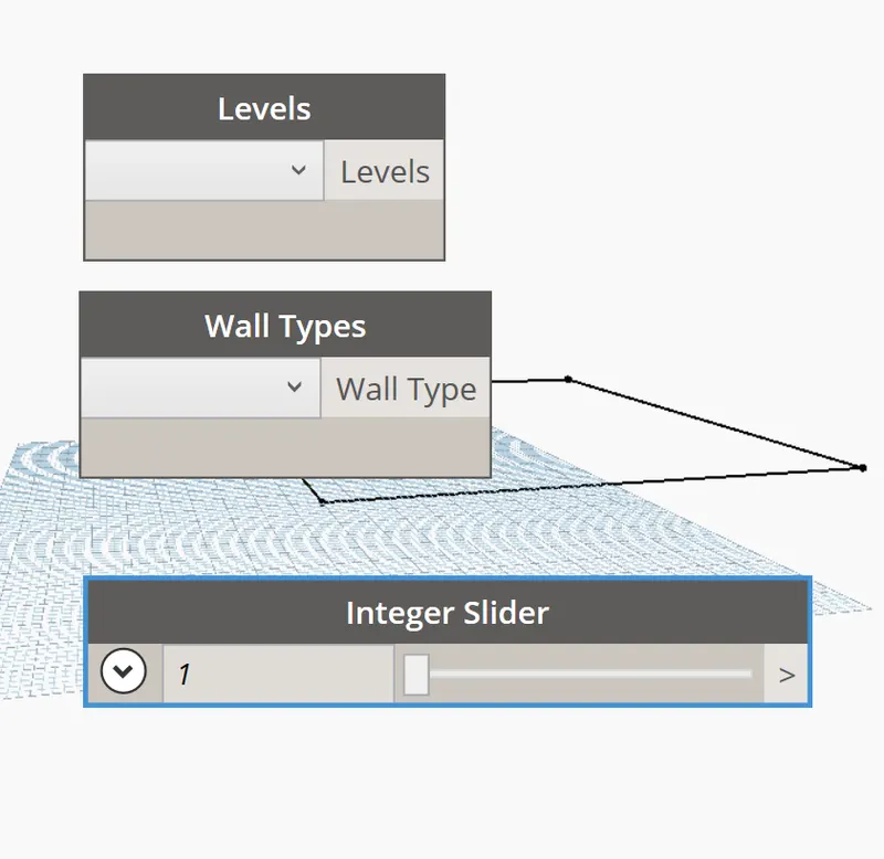
Type integer Slider in Library
Place Integer Slider block in the model space
Set Level to Level-1 in the Levels block
Set Wall Type to Generic Wall 200mm in the Wall Types block
Set Integer Slider to 10 value
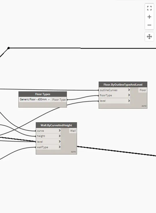
We have to connect Levels, Wall Type and Integer slider to WALLS by Curve and Height
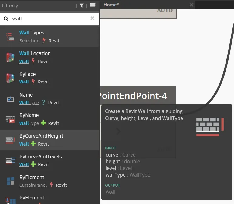
Type WALL in the Library
Click on ByCurveandHeight option from the dropdown list
Place WALL.ByCurveandHeight block in the model space
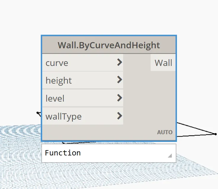
Connect List in List Create block to Curve in WALL.ByCurveandHeight block
Connect LEVELS in Level block to Level in WALL.ByCurveandHeight block
Connect Wall Type in Wall Types block to Wall Type in WALL.ByCurveandHeight block
Connect Integer Slider-3 block to Height in WALL.ByCurveandHeight block
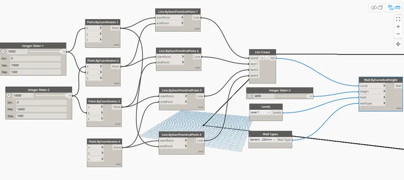
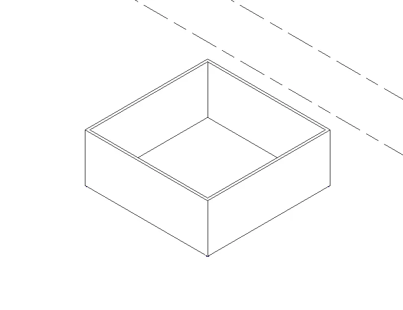
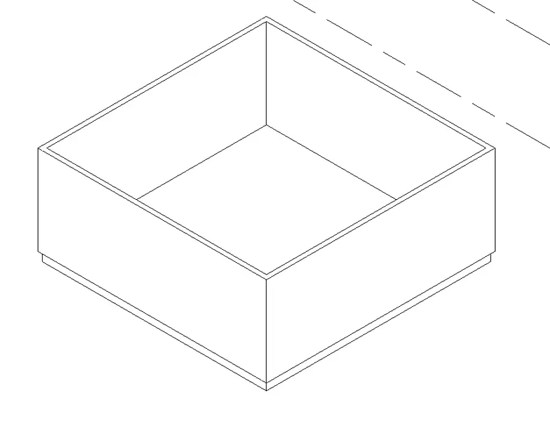
Walls are created in Revit.
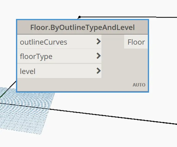
We have to create Floor.
Type Floor in Library.
Select ByOutlineTypeAndLevel option from the dropdown list
Place it on the model space.
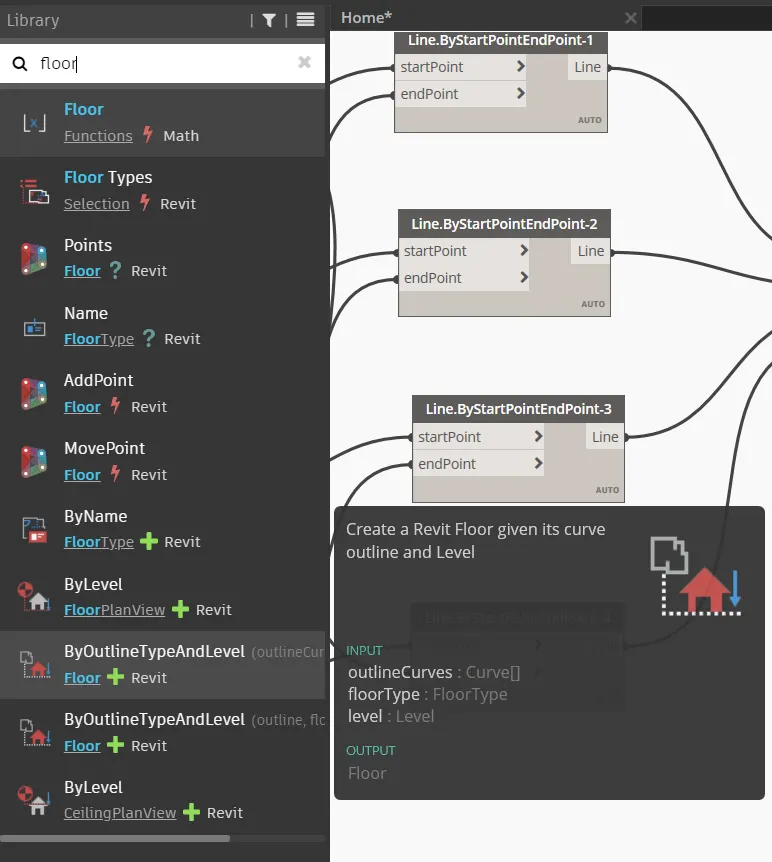
Type Floor in Library
Select FloorTypes option from the list
Place it on the model space.
Choose Generic Floor-400mm option in the Floor Type block
Connect FloorType option in Floor Type block to
floor type option in Floor.ByOutlineTypeAndLevel block
Connect Levels option in Levels block to
Level option in Floor.ByOutlineTypeAndLevel block
Connect List in List Create block to
Outline Curve in Floor.ByOutlineTypeAndLevel block
RESULT: -
We created Conceptual Layout of Floor Plan in Dynamo
Linked the lines to appropriate model elements in Revit by choosing the Wall types and Wall parameters.
Made use of sliders to slide through the height and Length of the wall.
3Q]
AIM: -
Create an Array of model elements in Revit
Use dynamo to vary the properties of model elements by using the slider or code block
PROCEDURE: -
Open Architectural Template in Revit
Click on Architecture Tab
Go to Build Panel
Click on Column tool
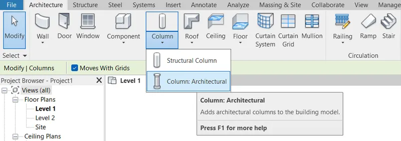
Choose Architecture Column from the list
Go to Properties
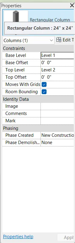
Select the Rectangular column 24’ x 24’
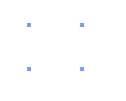
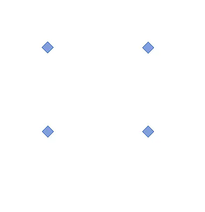
Place 4 columns in the model space
Click on MANAGE TAB
Go to Visual Programming panel
Select Dynamo
Dynamo app opens
In the Home page click on New
New Home page opens
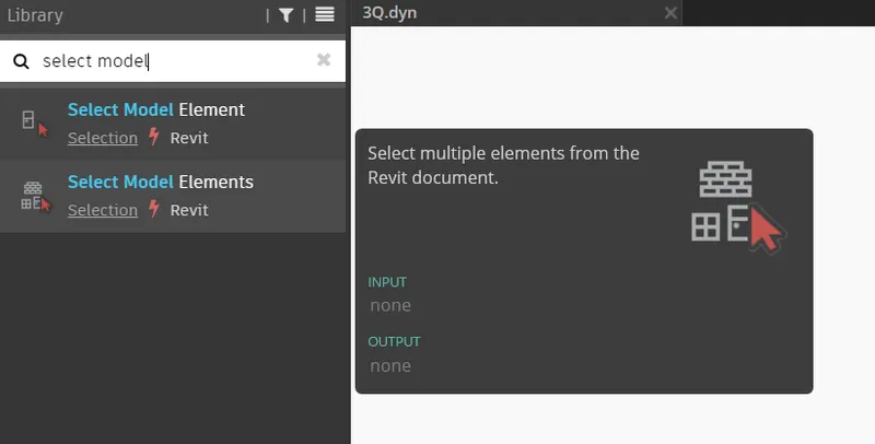
Type Select Model Elements in Library
Select Model Element (multiple) from the list
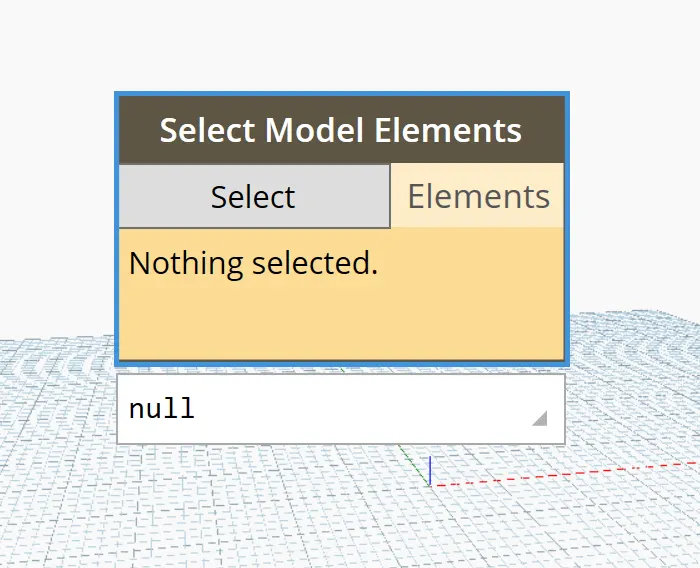
Place it in the model space.
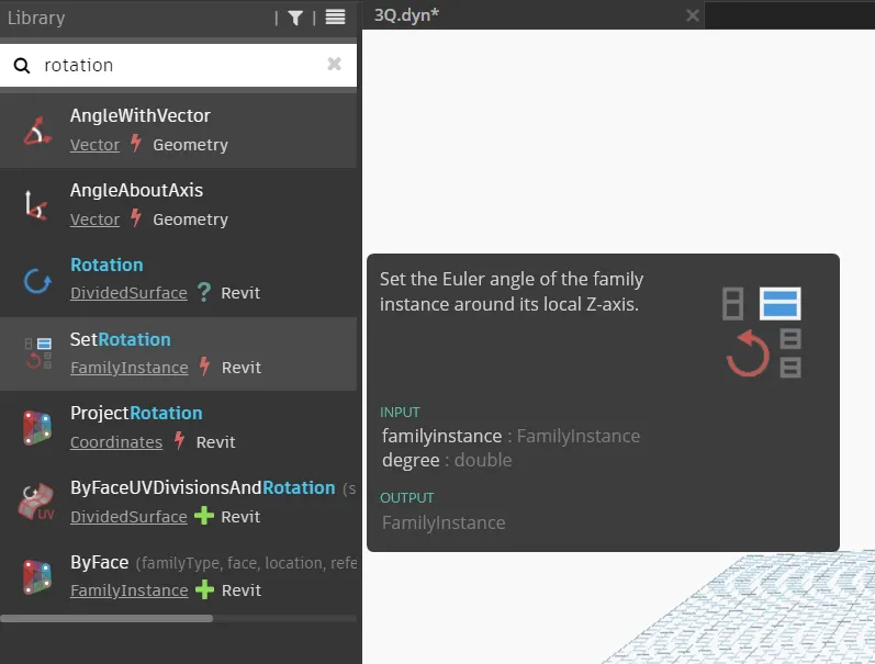
Type SetRotation in Library
Select SetRotation From the List
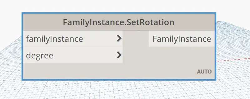
Place FamilyInstance.SetRotation block on the model space.
Type integer Slider in Library
Place Integer Slider block in the model space
Click on Select option in the Select Model Elements block
Go to Revit File
Select all the 4 columns
Selected columns are listed in the Dynamo
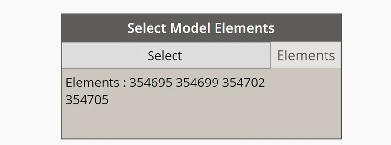
Connect Elements option in Select Model Elements block to
FamilyInstance option in FamilyInstance.SetRotation block
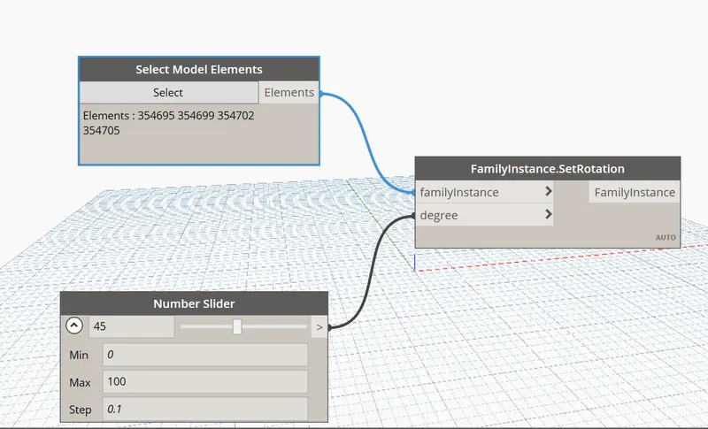
Check in Revit whether columns are rotated
We can see in Revit that Columns are rotated to 45 degrees.
RESULT: -
We created an Array of model elements in Revit.
Used dynamo to vary the properties of model elements by using the slider and Set Rotation block and Select model elements block.
4Q]
AIM: -
Create a conceptual Mass in Revit.
Develop a Parametric column by dividing the surfaces.
Apply the concepts similar to used in parametric walkway modelling.
Use Triangular bent or square shaped panels to add finish to the Parametric column.
PROCEDURE: -
Open Revit Software
Click on File
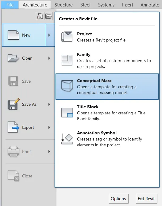
Select New from the dropdown list
Go to Conceptual Mass option
Click on the Conceptual mass
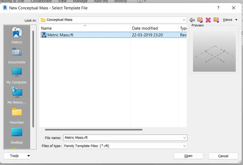
Conceptual mass Dialogue box opens
Select the Metric Mass.rft file
Press Ok
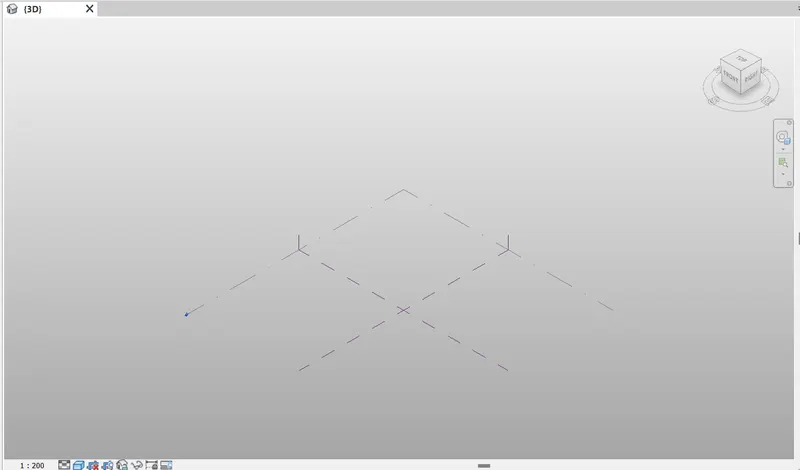
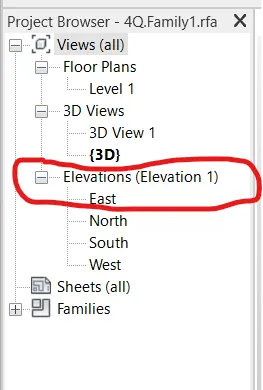
In Project Browser
Go to Elevations Panel
Click on EAST
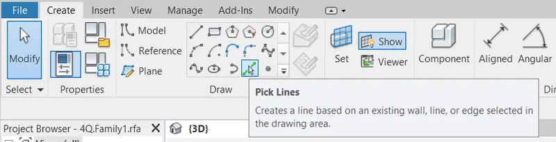
Go to Draw panel
Select Pick points tool
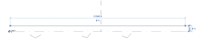
Provide offset distance: 12’
Click in Level 1 in the model space.
Click on Floor plan in the Project browser
Open Level 1 from Floor plan
Click on Model in the Draw panel
Select Spline tool
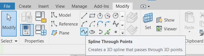
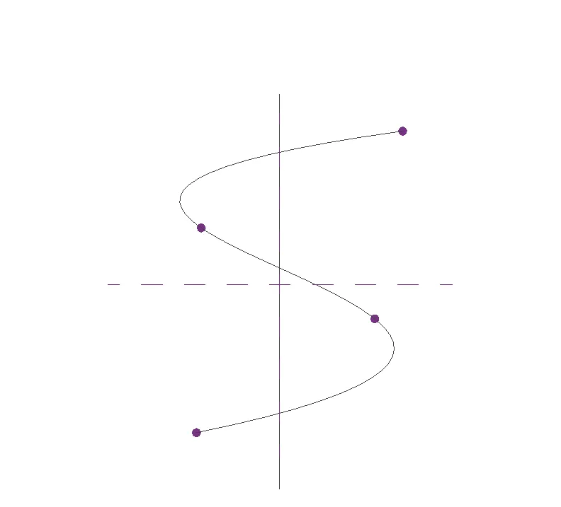
Create Spline in the model space
Press ENTER
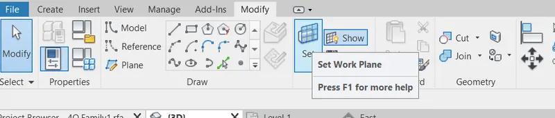
In the Modify Tab
Go to Work Plane panel
Choose Set option
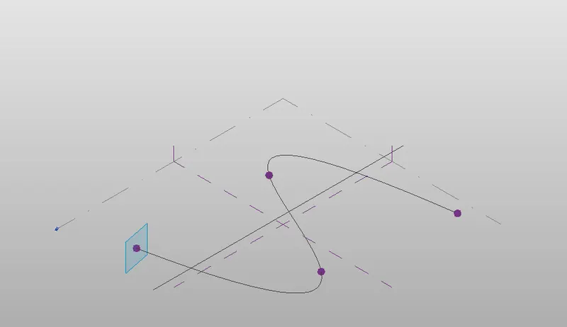
Click on points of the Spline in the model space
Click on Show tool in the Work Plane panel.
In the Modify Tab
Go to DRAW panel
Click on circumscribed polygon
Enter sides: 6
Click on the points of the Spline in the model space
Enter the Height: 12’
Press Enter
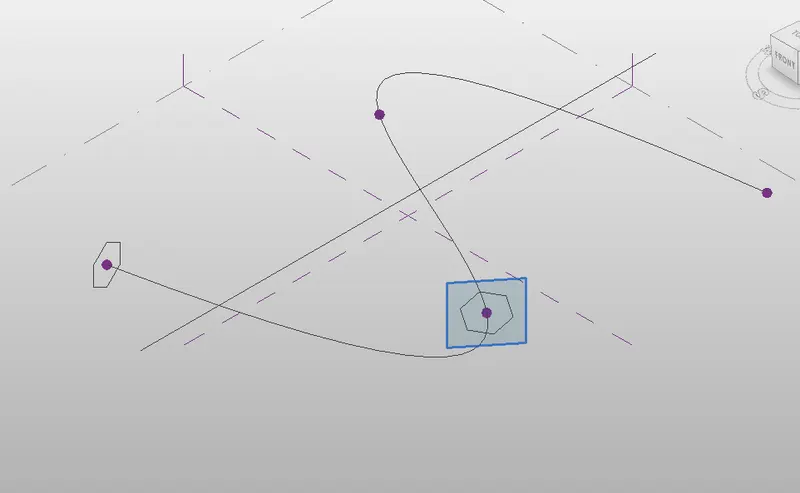
Repeat the same process for all the points of the Spline in the model space
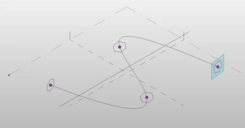
Click on CREATE TAB
Select Spine curve and Circumscribed polygon

Click on Create form tool
Select Solid Form
Press Enter

Now the Spline is converted to a Solid Form
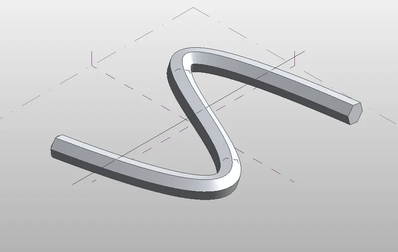
To apply the Triangular bent we have to Divide the surface.
Select all the Spline Solid
Click on Filter option
Choose only Form
Press APPLY
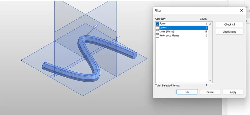
Now Click on Divide Surface Tool
Go to Properties
Click on the Pattern
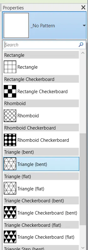
Select the Triangular bent option from the dropdown list.
Press Enter
Triangular bent property is applied to the Spline.
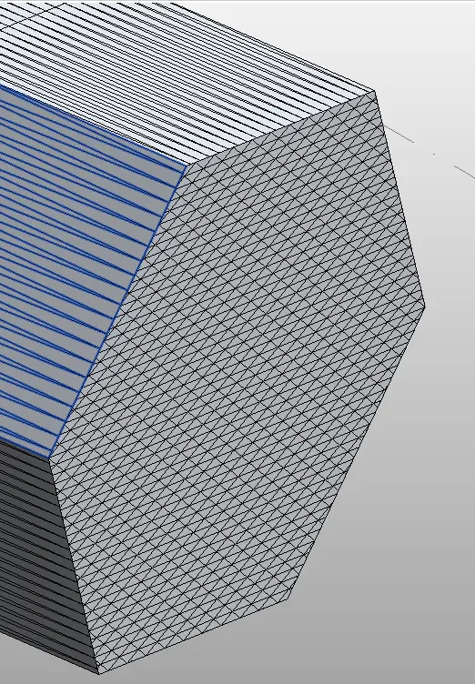
RESULT: -
We created a conceptual Mass in Revit.
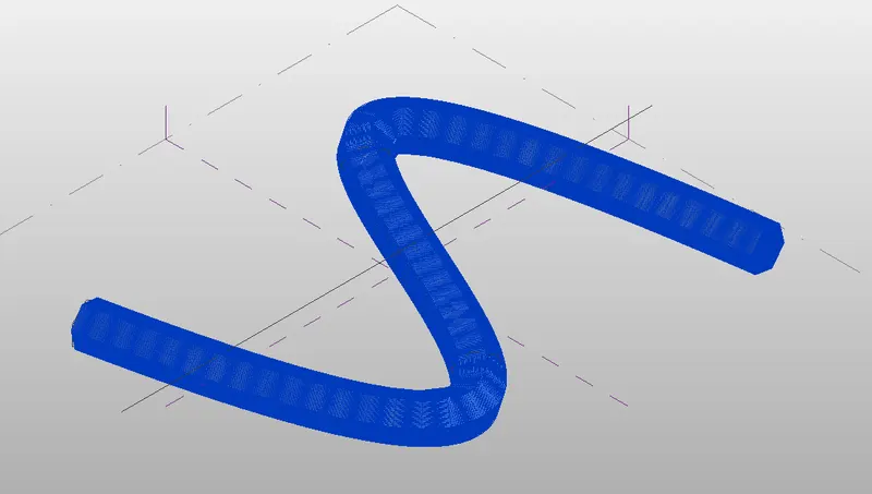
Developed a Parametric column by dividing the surfaces.
Applied the concepts similar to use in parametric walkway modelling.
Used Triangular bent to add finish to the Parametric column.
5Q]
AIM: -
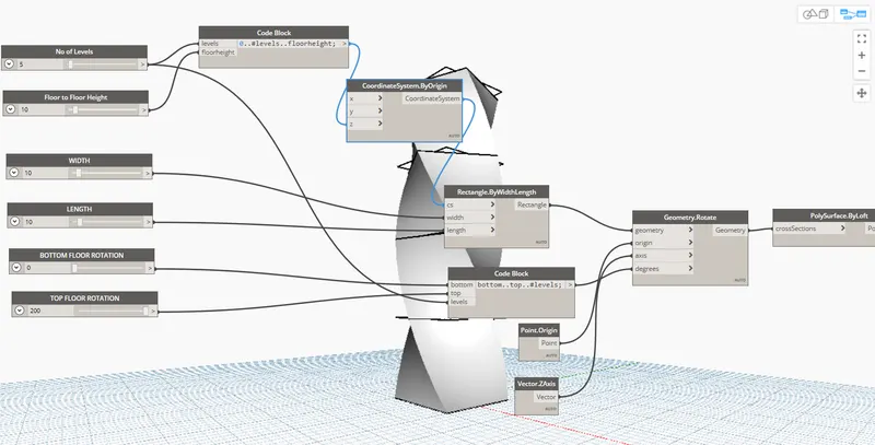
Develop a Parametric Stadium using Dynamo
List the Parameters and use the Visual programming approach to complete the model.
PROCEDURE: -
Open Architectural Template in Revit
Click on MANAGE TAB
Go to Visual Programming panel
Select Dynamo
Dynamo app opens
In the Home page click on New
New Home page opens
Now, we have to Insert Integer slider
For this, Go to Library
Type Integer slider
Click on the Integer Slider from the dropdown list
Integer slider block appears in the model space
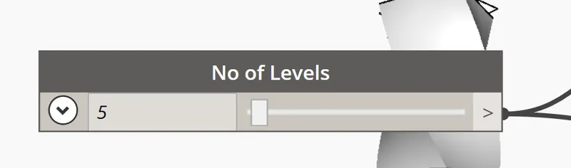
Change the name of the blocks to Floor to Floor Height
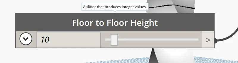
Type Integer slider
Click on the Integer Slider from the dropdown list
Integer slider block appears in the model space
Change the name of the blocks to No of Levels
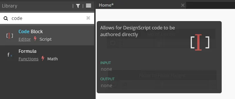
Type CODEBLOCK
Click on the Code Block from the dropdown list
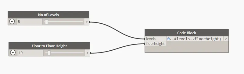
Connect No of Levels block to Levels option in Code block
Connect Floor Height block to Floor height option in Code block
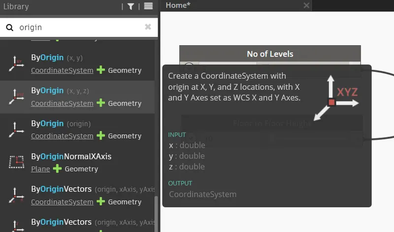
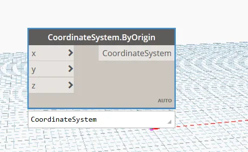
Type ORIGIN in Library
Select ByOrigin(x,y,z) from the list
Place it in the model space.
Type Integer slider
Click on the Integer Slider from the dropdown list
Integer slider block appears in the model space
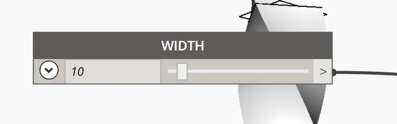
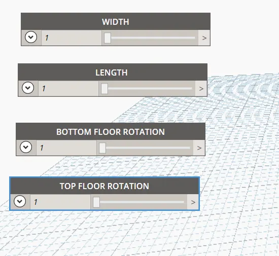
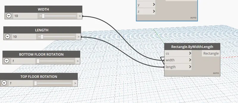
Change the name of the block to WIDTH
Type Integer slider
Click on the Integer Slider from the dropdown list
Integer slider block appears in the model space
Change the name of the block to WIDTH
Type Integer slider
Click on the Integer Slider from the dropdown list
Integer slider block appears in the model space
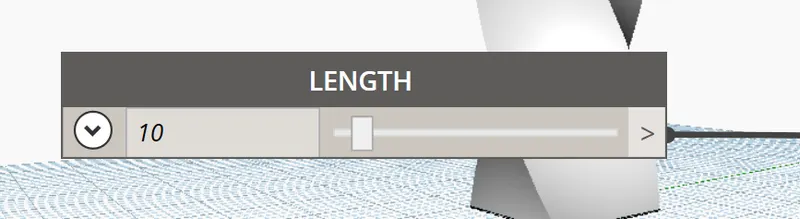
Change the name of the block to LENGTH
Type Integer slider
Click on the Integer Slider from the dropdown list
Integer slider block appears in the model space
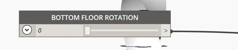
Change the name of the block to BOTTOM FLOOR ROTATION
Type Integer slider
Click on the Integer Slider from the dropdown list
Integer slider block appears in the model space
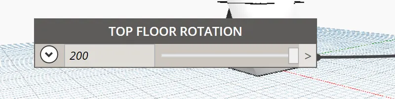
Change the name of the block to TOP FLOOR ROTATION
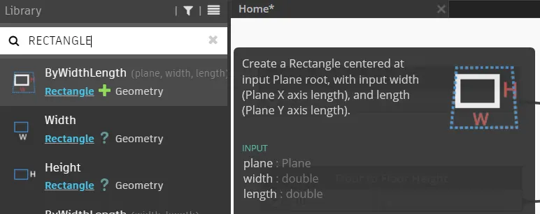
Type RECTANGLE in Library
Click on the ByWidthLength (cs, width, length) option from the dropdown list
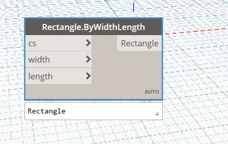
Connect WIDTH block to Width option in Rectangle.byWidthLength block
Connect LENGTH block to Length option in Rectangle.byWidthLength block
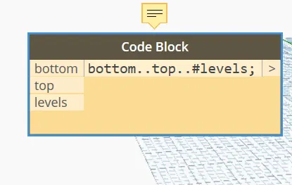
Type CODEBLOCK
Click on the Code Block from the dropdown list
Write the code in the block
bottom..top..#levels
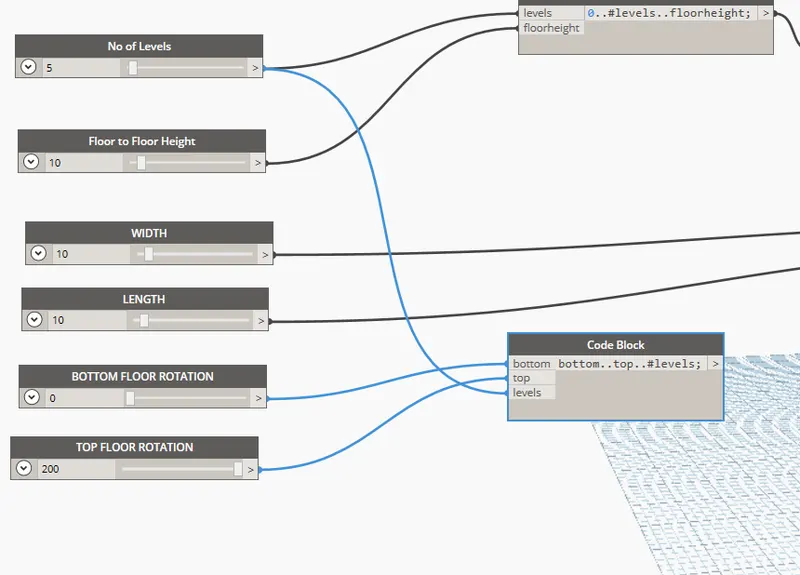
Connect BOTTOM Floor Rotation block to bottom option in Code block
Connect Top Floor Rotation block to Top option in Code block
Connect Levels option in No of Levels block to Levels option in Code block
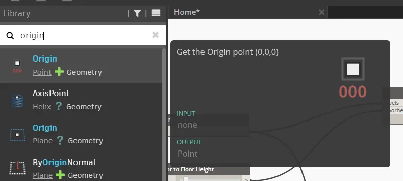
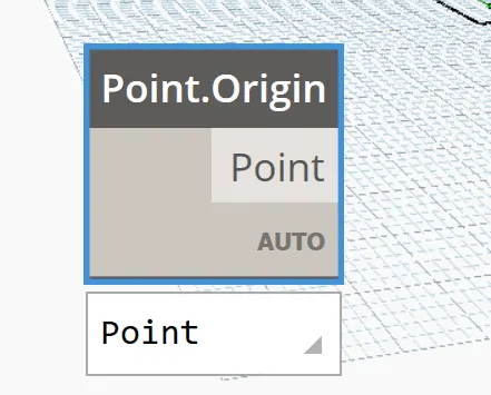
Type ORIGIN in library
Select Point.Origin option from the List
Place Point.origin block in the model space.
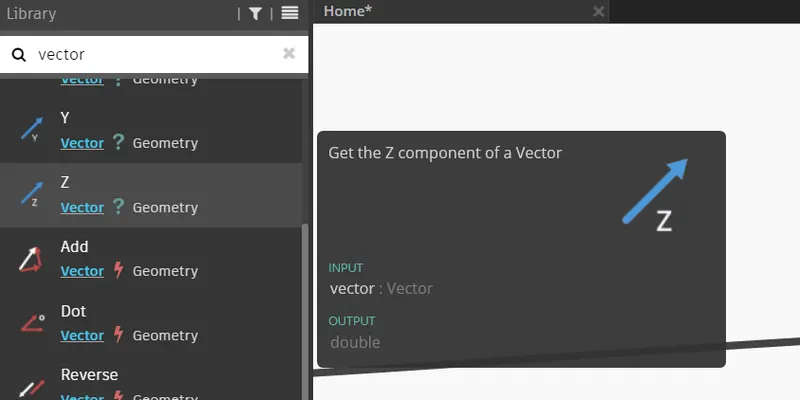
Type VECTOR in library
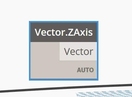
Select Vecor.ZAxis option from the List
Place Vecor.ZAxis block in the model space.
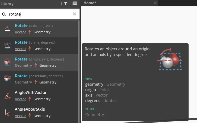
Type ROTATE in library
Select ROTATE (origin, axis, degree) option from the list
Place Geometry.Rotate block in the model space.
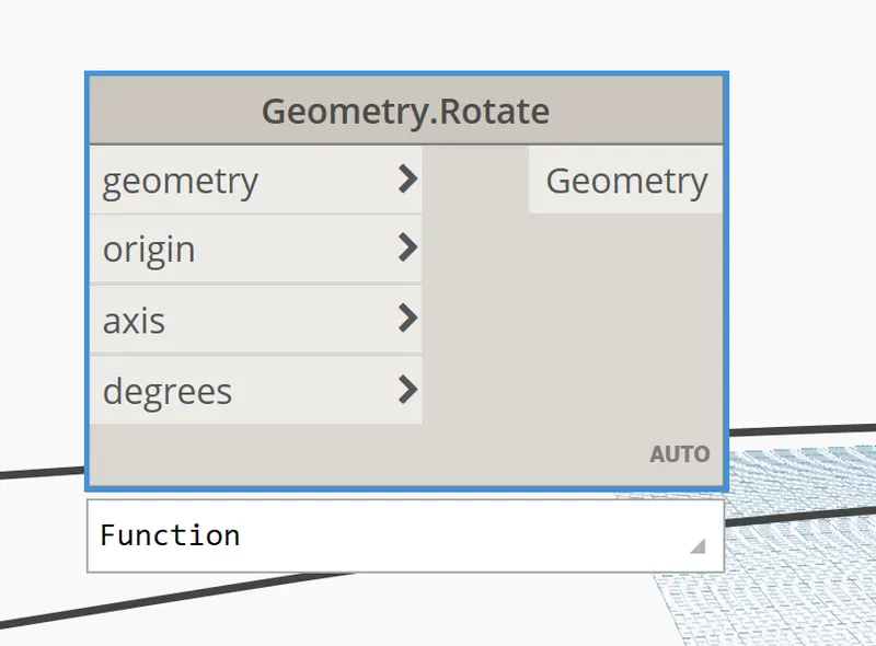
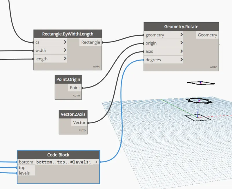
Connect Rectangle option in Rectangle.byWidthLength block to Geometry option in Geometry.Rotate block
Connect point option in Point.origin block to Origin option in Geometry.Rotate block
Connect Vector option in Vecor.ZAxis block to Axis option in Geometry.Rotate block
Connect Codeblock to degrees option in Geometry.Rotate block
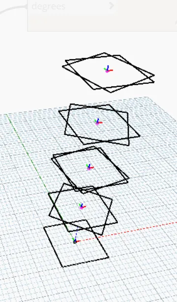
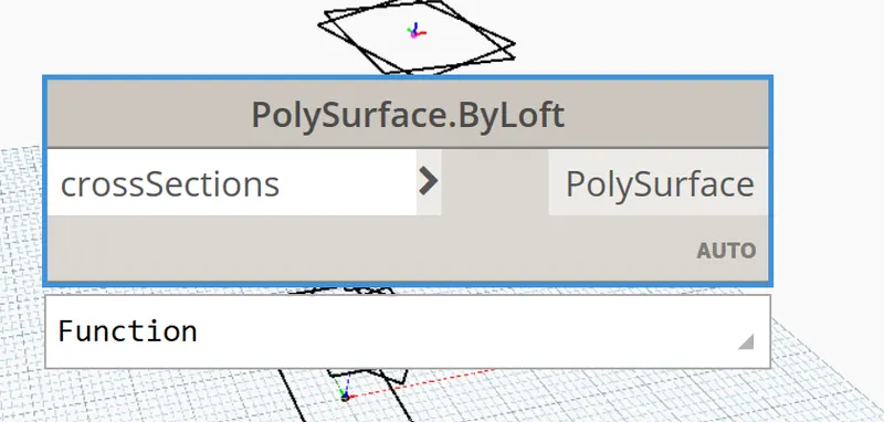
Type Polysurface in Library
Select ByLoft (cross sections) option from the list
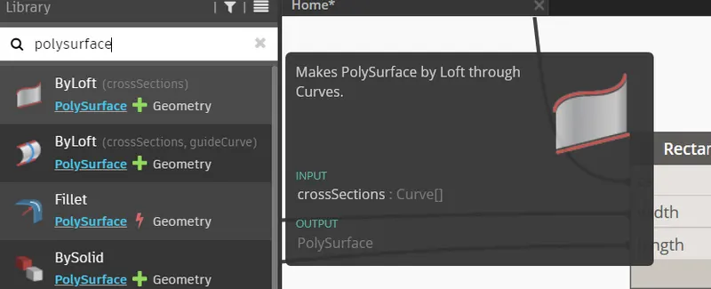
Place PolySurface.byLoft block in the model space.
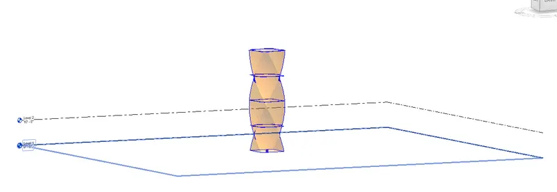
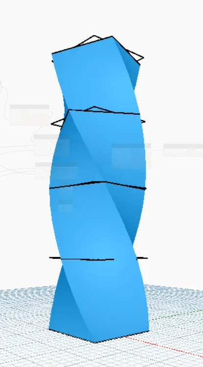
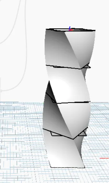
Created parametric Structure
RESULT: -
We Developed a Parametric Stadium using Dynamo
Listed the Parameters and used the Visual programming approach to complete the modelling.