Creating Conceptual mass in REVIT and Creation of Sinusoidal curve and a Parametric stadium using Dynamo
1) Using Dynamo create a set of sinusoidal points and create a curve and create a surface out of the curve.
AIM :
To Using Dynamo create a set of sinusoidal points and create a curve and create a surface out of the curve.
INTRODUCTION :
- Using Dynamo, you can work with enhanced BIM capabilities in Revit. Dynamo and Revit together can be utilized to model and analyze complex geometries, automate repetitive processes, minimize human error, and export data to Excel files and other file-types not typically supported by Revit
- Dynamos, usually driven by steam engines, were widely used in power stations to generate electricity for industrial and domestic purposes. They have since been replaced by alternators.
- Dynamo is an open source visual programming platform for designers. It is installed as part of Revit along with Revit specific programming nodes. To access Dynamo, click Manage tab Visual Programming panel Dynamo.
PROCEDURE :
- Open the revit soft ware
- Use the dynamo option in the manage tool bar
- After open the dynamo software, just use the search box for pick the wanted code boxes.
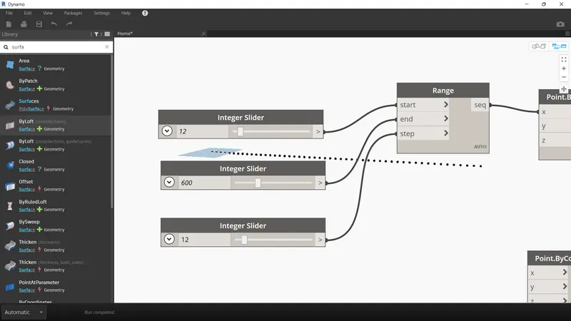
- Search the name integer and pick the integer slider 3 time. the image given below
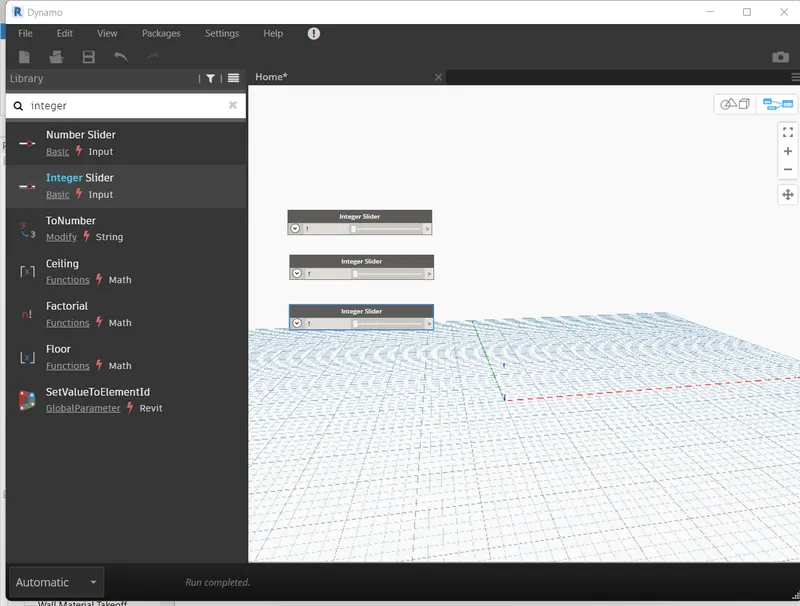
- Set the integer slider value as
first slider = 12
second slider = 600
third slider = 12
- Search the name range, and pick the range option
- And connect the first integer slider to start, second integer slider to end, third integer slider to step
- Search the point.by coordinate and select the coordinate
- And the range (seq) connect to the point.by coordinate (x) value
- After connection this we can see the creation of dotted.
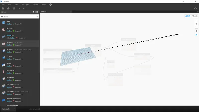
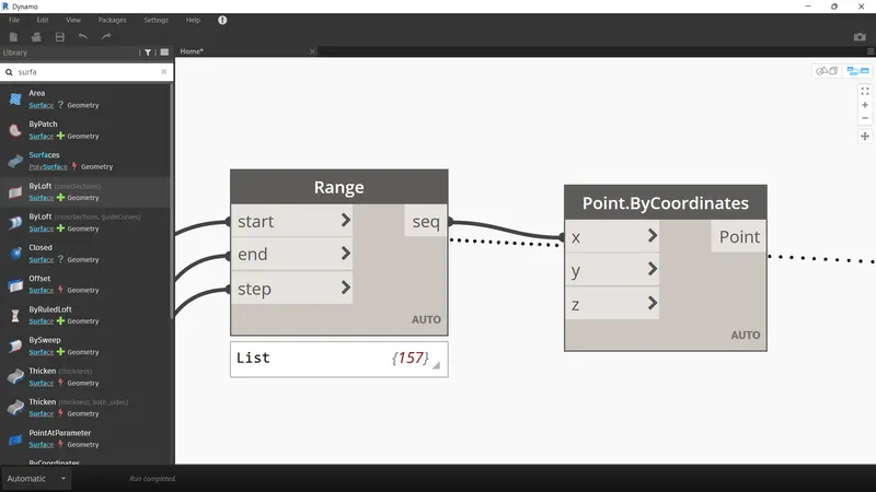
-
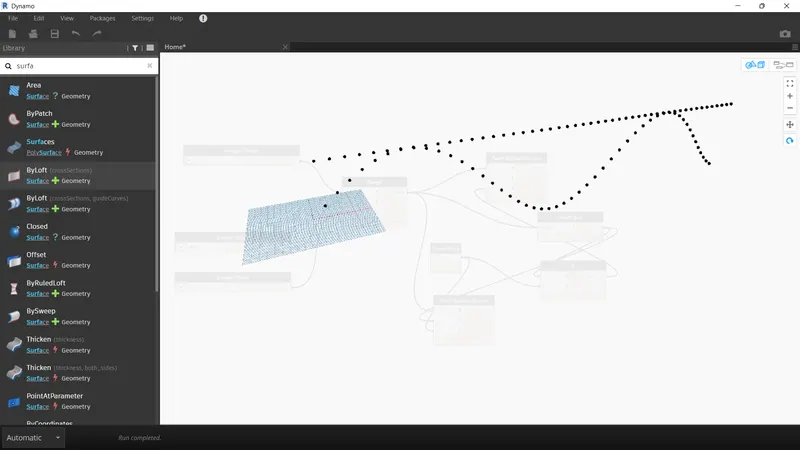
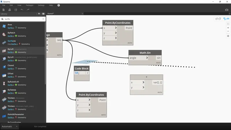
Next type math.sin and connect the range seq to the angle, as shown below.
Next type product connect sin to the x. -
Next type code block and rename it as amplifier and connect it to y of the product.
-
Next type add and insert it and connect var of product to the x of add, as shown below.
-
Next connect var of add to the y of the point bycoordinates.
-
Next we type integer slider and give the minimum integer value as 20, and connect it to the y of add.
-
Next type nurbscurve coordinate and insert it.
-
Next connect point of point by coordinates to the points of nurbscurve coordinates, as shown in the below figure.
-
Next again type integer slider and give the minimum integer value as 5, and connect it to the degree of nurbscurve bycontrolpoints, as shown below.
- Copy the group and paste
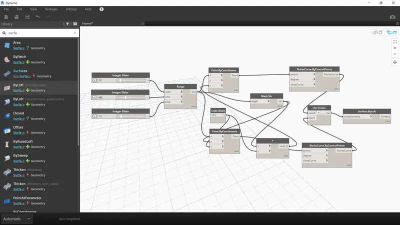
- Type the list create and insert 4 times
- After connecting the nurbscurve of all 4 boxes
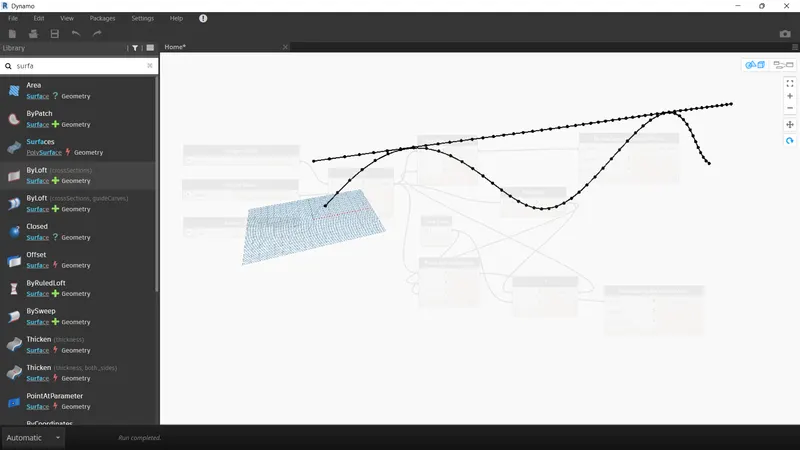
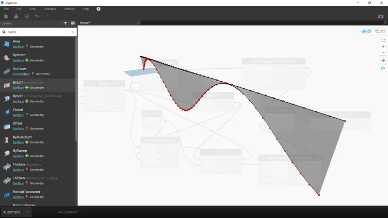
- finally the surface has been created
RESULT :
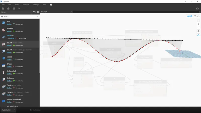
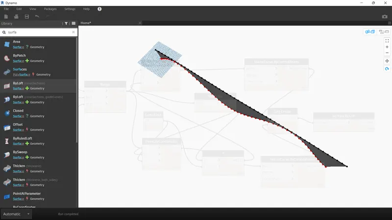
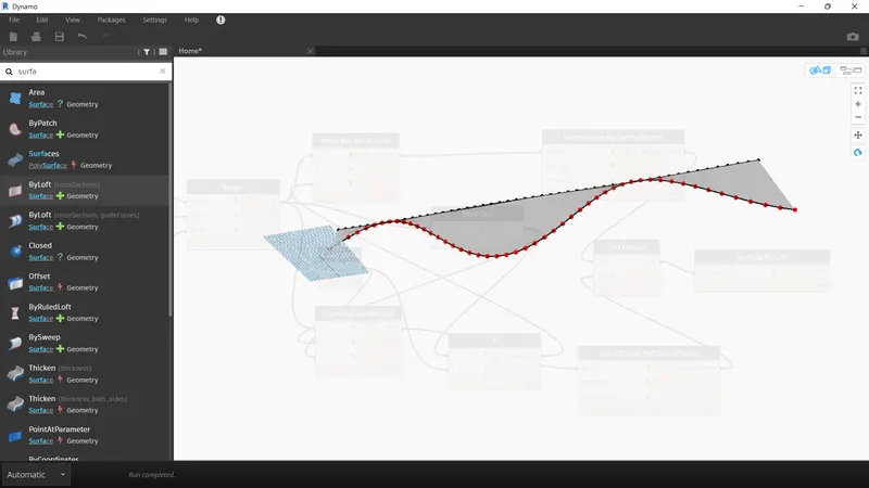
2) Create a conceptual layout of floor plan in dynamo . Using the tools available in dynamo link the lines to appropriate model elements in Revit by choosing the wall types and wall parameters. Make use of the sliders to slide through the height of the wall and length of the wall.
AIM :
To Create a conceptual layout of floor plan in dynamo . Using the tools available in dynamo link the lines to appropriate model elements in Revit by choosing the wall types and wall parameters. Make use of the sliders to slide through the height of the wall and length of the wall.
INTRODUCTION :
- Using Dynamo, you can work with enhanced BIM capabilities in Revit. Dynamo and Revit together can be utilized to model and analyze complex geometries, automate repetitive processes, minimize human error, and export data to Excel files and other file-types not typically supported by Revit
- Dynamos, usually driven by steam engines, were widely used in power stations to generate electricity for industrial and domestic purposes. They have since been replaced by alternators.
- Dynamo is an open source visual programming platform for designers. It is installed as part of Revit along with Revit specific programming nodes. To access Dynamo, click Manage tab Visual Programming panel Dynamo.
PROCEDURE :
- In this project we want create the wall in dynamo
- So first open the revit and open the manage tab and pick the dynamo
- Then search the integer slider and pick the slider box as two times
- Make them the value of integer slider as 125 of both slider
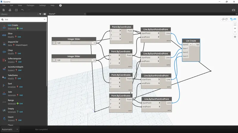
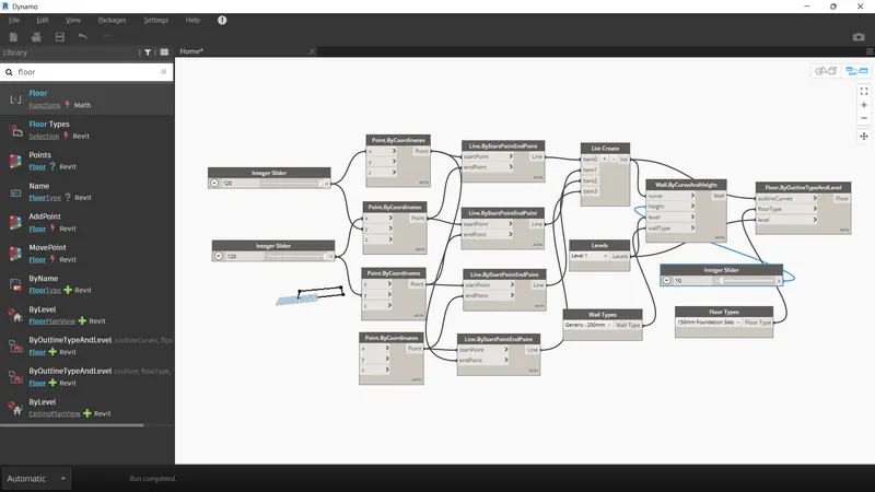
- And search the point.by coordinate and pick the coordinate as four times
- And connect the first slider to first point.by coordinate (x) value , first slider to second point.by coordinate (y) value.
- Then connect second integer slider to second point.by coordinate (x) value, and second slider to third point.by coordinate (y) value
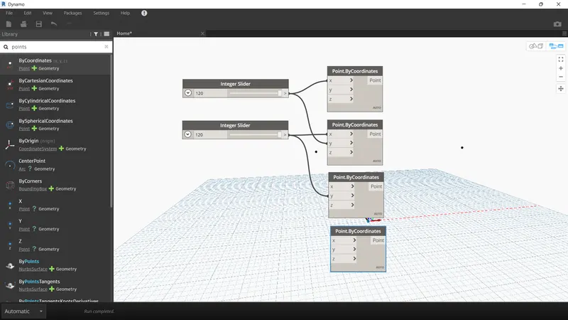
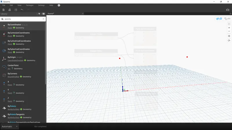
- Then we can se the point as created in the image as given below
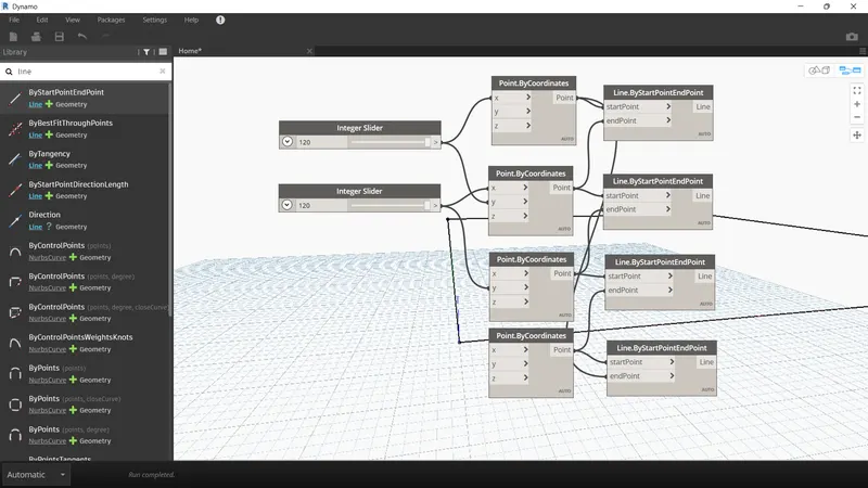
- Search the name line and select line by startpoint end point box 4 times
- connect the point.by coordinate and line.by start point end point box
1.) 1st point.by coordinate (point) to 1st line.bystartpointendpoint box (start point)
2.) 2nd point.by coordinate (point) to 1st line.bystartpointendpoint box (end point)
3.) 2nd point.by coordinate (point) to 2nd line.bystartpointendpoint box (start point)
4.) 3rd point.by coordinate (point) to 2nd line.bystartpointendpoint box (end point)
5.) 3rd point.by coordinate (point) to 3rd line.bystartpointendpoint box (start point)
6.) 4th point.by coordinate (point) to 3rd line.bystartpointendpoint box (end point)
5.) 4th point.by coordinate (point) to 4th line.bystartpointendpoint box (start point)
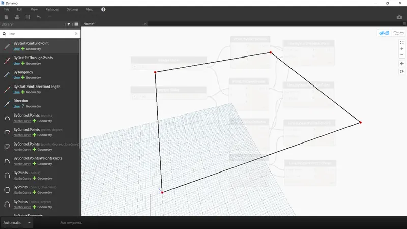
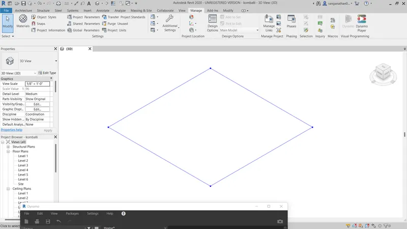
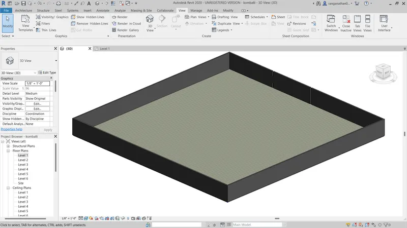
- Here we can see the wall can be created and also created in revit
- Search the name list and select the list created box
- Pick the line.byStartPointEndPoint and connect to list create box
1.) 1st line.byStartPointEndPoint (line) and connect to list create box (item 0)
2.) 2nd line.byStartPointEndPoint (line) and connect to list create box (item 1)
3.) 3rd line.byStartPointEndPoint (line) and connect to list create box (item 2)
4.) 4th line.byStartPointEndPoint (line) and connect to list create box (item 3)
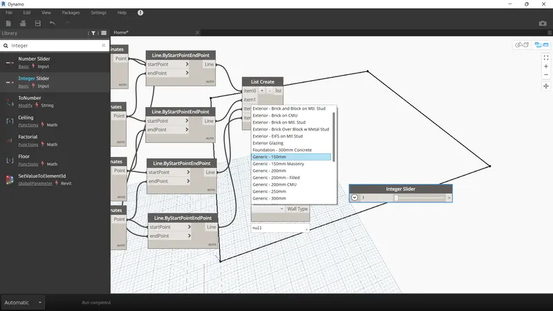
- Here we can seen the wall as been created and then also wall created in revit
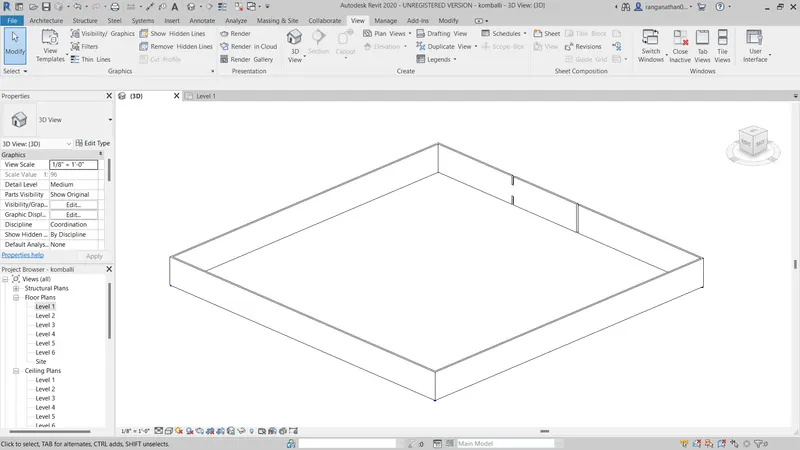
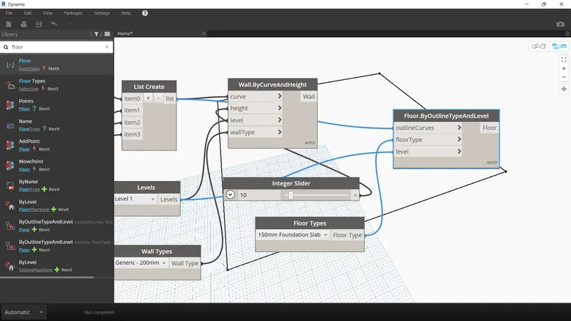
RESULT :
3) Create an array of model elements in Revit. Use dynamo to vary the properties of model elements by using the slider or code block
AIM :
To Create an array of model elements in Revit. Use dynamo to vary the properties of model elements by using the slider or code block
INTRODUCTION :
- Using Dynamo, you can work with enhanced BIM capabilities in Revit. Dynamo and Revit together can be utilized to model and analyze complex geometries, automate repetitive processes, minimize human error, and export data to Excel files and other file-types not typically supported by Revit
- Dynamos, usually driven by steam engines, were widely used in power stations to generate electricity for industrial and domestic purposes. They have since been replaced by alternators.
- Dynamo is an open source visual programming platform for designers. It is installed as part of Revit along with Revit specific programming nodes. To access Dynamo, click Manage tab Visual Programming panel Dynamo.
PROCEDURE :
- Open the architectural revit file
- Set the unit and select the column as used in components tab
- In the components pick the architectural column
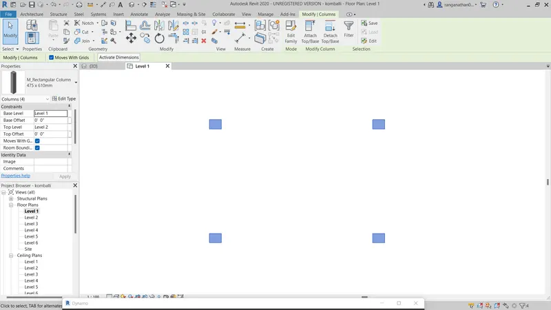
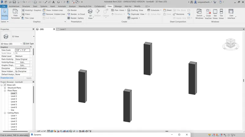
- And draw the 4 column on the screen
- Then open the dynamo option in the manage tab
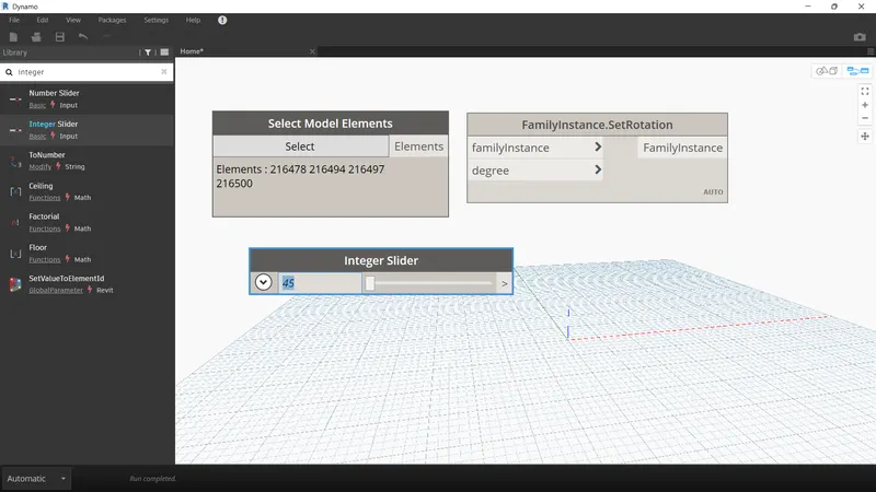
- Search the select model elements and pick it
- And search rotation and pick familyinstance.set rotation
- also search integer slider and set value 45
- And make pick select option in select model element and select the column in revit
- finally adjust the integer slider and see the column as been automatically rotated can be visible
RESULT :
4) Create a conceptual mass in Revit and develop a parametric column by dividing the surfaces and apply the concepts similar to used in parametric walkway modelling. Use triangular bent or square shaped panels to add finish to the parametric column
AIM :
To Create a conceptual mass in Revit and develop a parametric column by dividing the surfaces and apply the concepts similar to used in parametric walkway modelling. Use triangular bent or square shaped panels to add finish to the parametric column
INTRODUCTION :
- Using Dynamo, you can work with enhanced BIM capabilities in Revit. Dynamo and Revit together can be utilized to model and analyze complex geometries, automate repetitive processes, minimize human error, and export data to Excel files and other file-types not typically supported by Revit
- Dynamos, usually driven by steam engines, were widely used in power stations to generate electricity for industrial and domestic purposes. They have since been replaced by alternators.
- Dynamo is an open source visual programming platform for designers. It is installed as part of Revit along with Revit specific programming nodes. To access Dynamo, click Manage tab Visual Programming panel Dynamo.
PROCEDURE :
- Open the revit file
- Go to the file and select new option
- Then select the conceptual mass
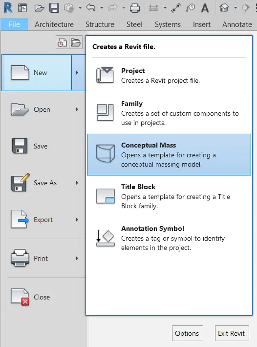
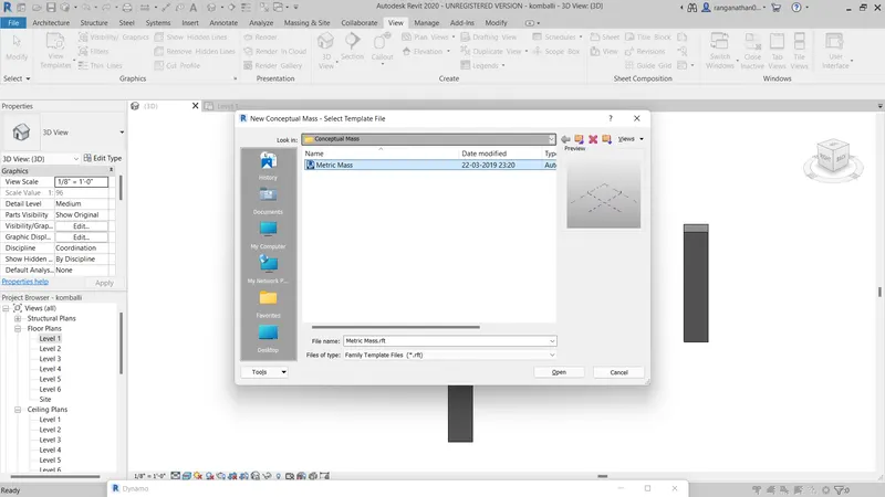
- Open the conceptual mass and select the metric mass then click ok.
- Go to the elevation view and create the level 10 feet
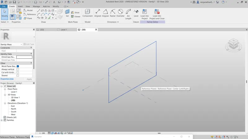
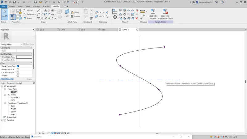
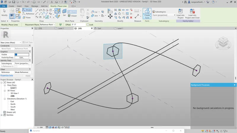
- Now using the spline tool and draw the desired outline for the walkway
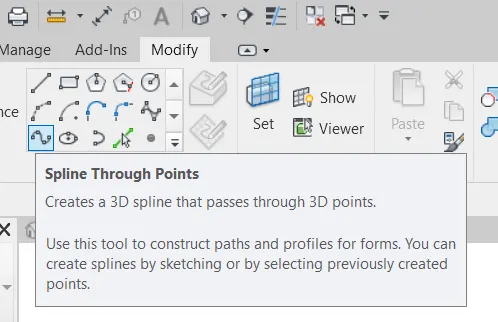
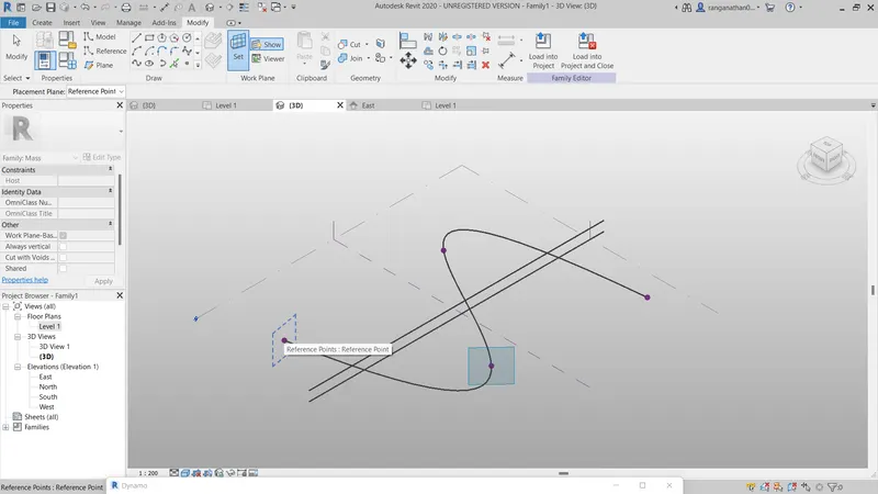
-
Now, we have to create a profile to sweep through the curve.
-
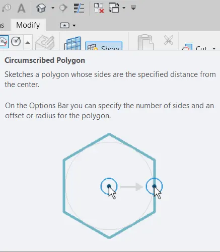
For this, we have to set the workplane at the points and develop a polygon at the workplane keeping the point as centre.
-
Now, a polygon is developed with point as center.
-
Similarly, workplane and polygon is developed at all the nodes.
-
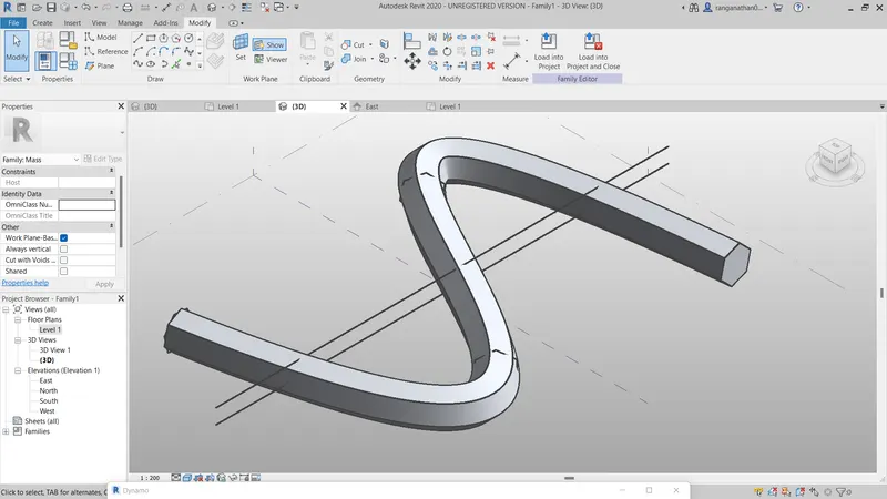
Now, we have to create the surface which done through sweep.
-
For this, select all the polygons and the curve line and choose create form option
-
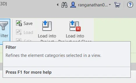
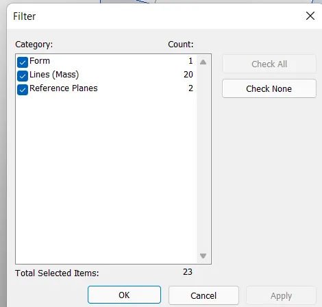
Now, select the entire form and then filter and retain only the form.
-
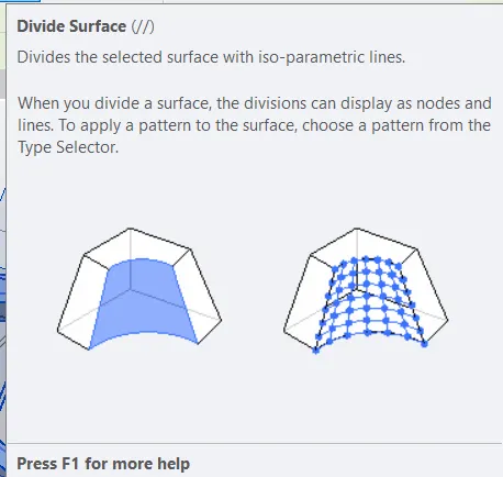
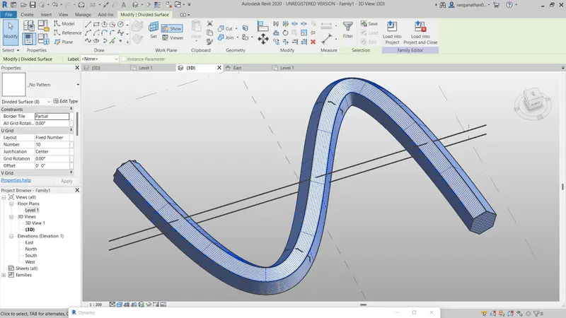
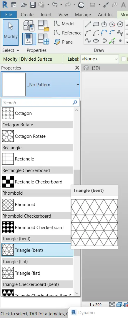
Now, select the form --> divide surface --> Then provide the pattern (triangle bent).
-
Now, open a new family -->Curtain panel pattern based.
- Then, create a reference point at centre of the face.
- Then draw a circle of radius 3" at that reference point.
- Now, select the pattern, refrence plane and circle created and choose create form.
- Now, load this into the project.
- Now, select the entre form of the walkway and filter it to retain only the divided surface.
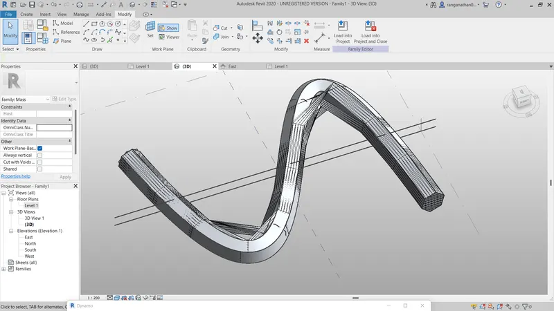
- Then in the pattern select the family that we havee created just now. Hence, the conceptual mass have been created
RESULT :
5) Use Dynamo to work on developing a Parametric Stadium. List your parameters and use the visual programming approach to complete the modelling, You can use the concepts discussed in parametric high rise tower in class for reference.
AIM :
To Use Dynamo to work on developing a Parametric Stadium. List your parameters and use the visual programming approach to complete the modelling, You can use the concepts discussed in parametric high rise tower in class for reference.
INTRODUCTION :
- Using Dynamo, you can work with enhanced BIM capabilities in Revit. Dynamo and Revit together can be utilized to model and analyze complex geometries, automate repetitive processes, minimize human error, and export data to Excel files and other file-types not typically supported by Revit
- Dynamos, usually driven by steam engines, were widely used in power stations to generate electricity for industrial and domestic purposes. They have since been replaced by alternators.
- Dynamo is an open source visual programming platform for designers. It is installed as part of Revit along with Revit specific programming nodes. To access Dynamo, click Manage tab Visual Programming panel Dynamo.
PROCEDURE :
-
First we have to open the new file in revit, and open the dynamo.
-
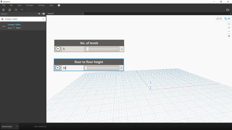
In the dynamo screen type slider and insert four sliders and rename it.
-
Next type points and select points by coordinate to create floor.
-
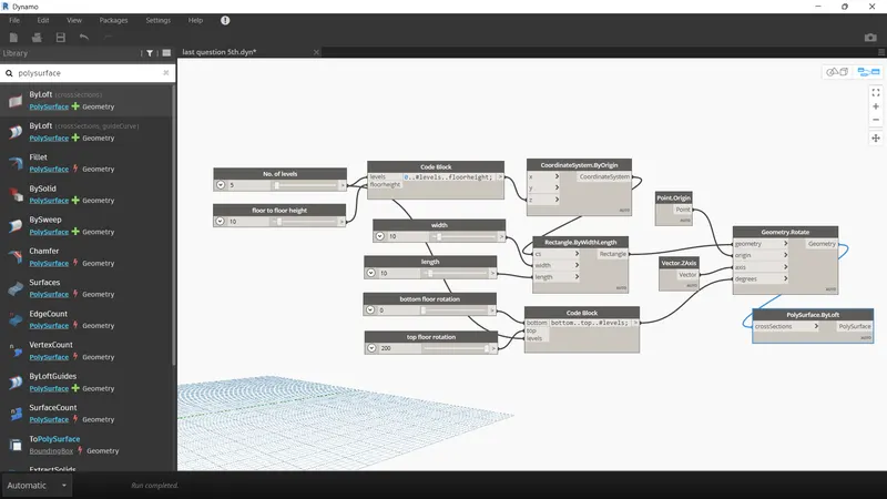
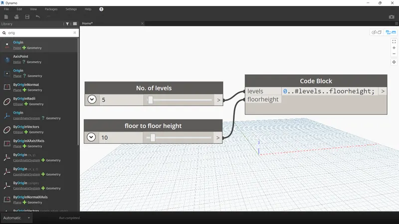
Next type code block and in that code block type (0.#levels.FloorHeight)
-
Next join levels and height, as shown below. Next type coordinate system by origin and join the code block to it in z.
-
Next type code block and in that code block type (bottom.top.#levels)
-
Next join the bottom rotation and top rotation and number of levels.
-
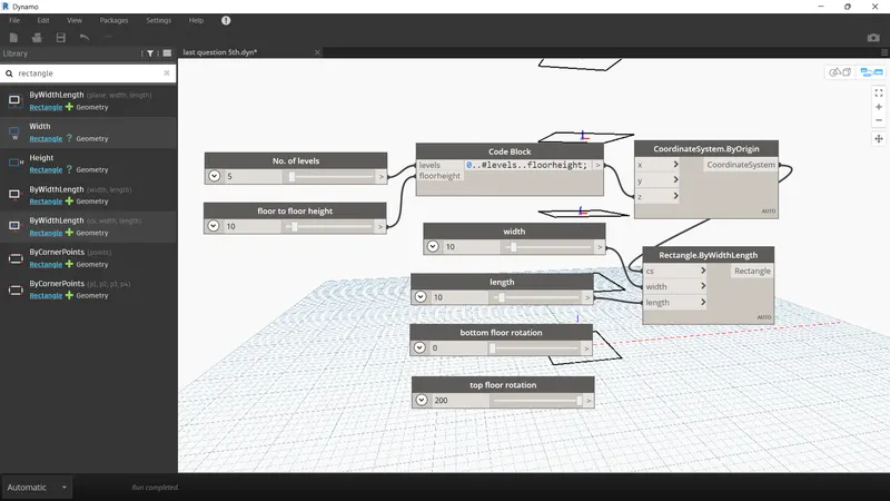
Next type rectanglebywidth, and type slider and rename it as width/length of rectangle.
-
Next join the coordinatesystem to cs.
-
Next join the slider to width and length.
-
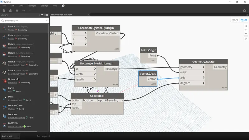
Next type rotate and insert geometry rotate.
-
Next type origin and insert point origin.
-
Next we have to type z axis & insert it.
-
Next join the rectangle to geometry point to origin and degrees to code book(bottom.top.#Levels).
-
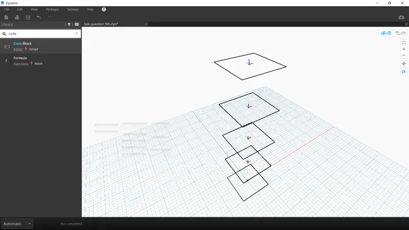
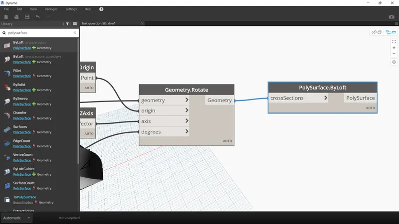
Next type polysurface by loft and insert it.
-
Next join geometry to the cross-section.
-
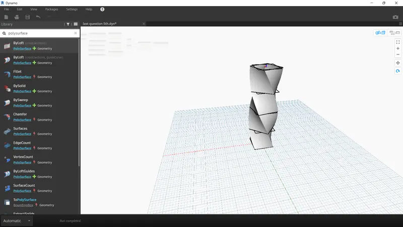
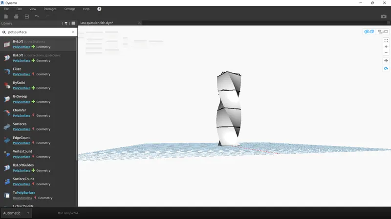
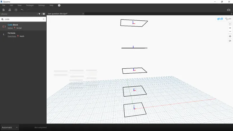
Therefore, the parametric stadium has been developed, as shown in the below figure.
-
Next we hide the total group and then we can see the parametric stadium clearly.
-
The parametric stadium has been created successfully, as shown in the below figure.
RESULT :