Creating Conceptual mass in REVIT and Creation of Sinusoidal curve and a Parametric stadium using Dynamo
Creating Conceptual mass in revit and creation of sinusoidal curve and a parametric stadium using dynamo
- Introduction
- Dynamo is an open source visual programming language for revit,written by designer and construction professional.Its a programming language that allows you to type lines of code,while creating on algorithm that consist of nodes.Using dynamo work can be carried out with enhanced BIM capabilities in revit dynamo and revit on together be utilised to model and analyze complex geopmetric,AUtomate repetative process minimize human error and export data to exer and other file types.Dynamo can make the design process more efficent with an intuitive interface and many pre mode scripting libraries available as well
- The user interface for dynamo is organized into five main area largest being the workspasce where programms are processed and this user interface section include
- Main menu
- TOolbar
- Library
- WOrk space
- Exucution bar
- The workspace is the place where designer devlop visual programm but it is also the place where any eloborate geometry is previewed
- Conceptual mass of a building contains diffrent types of parameter like level ,floor area ,Fkkoor perimeter and architect can generous early quantites takeoff from tbhe mass.In BIM modelling service the conceptual mass of a building can be exported toi any other format for performing early energy analysis
- AIM: To create a set of sinusoidal poijnt ,a curve and surface out of the curve using dynamo
- PROCEDURE:
- Initilly open the architecture tewmplate of revit software and go to manage tab
- In manage tab select the dynamo
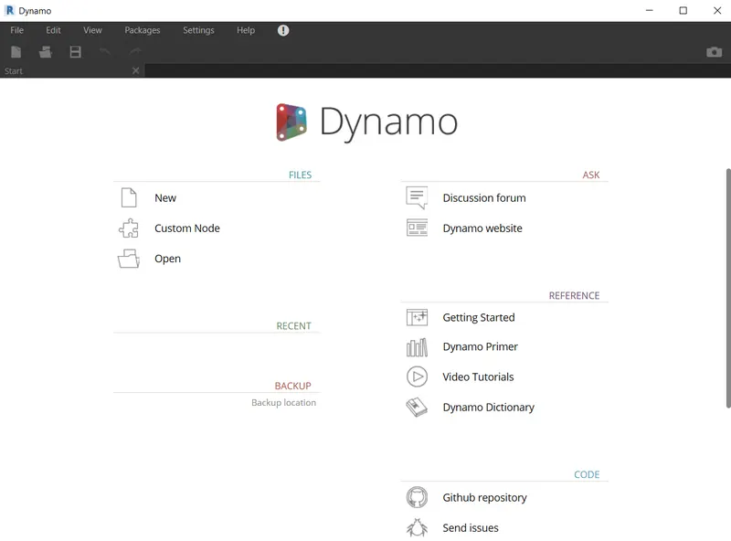
- Then dyanmo window open and thengo to new option

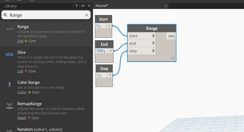
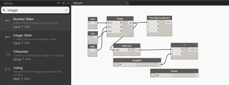
- Now,start the process by insecting three integer sider
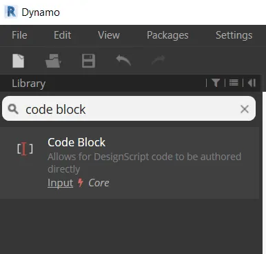
- This cant be done by typing copde black in the liabrary search panel
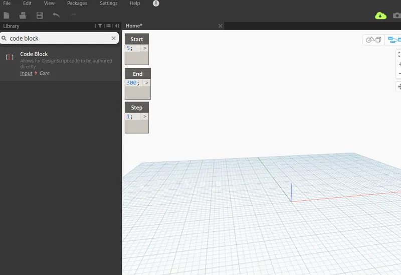
- One black is named start (value-5)
- Second one end(Value-300)
- Third one step(value-1)
- Now,type range in the search panel of the liabrary and insert it
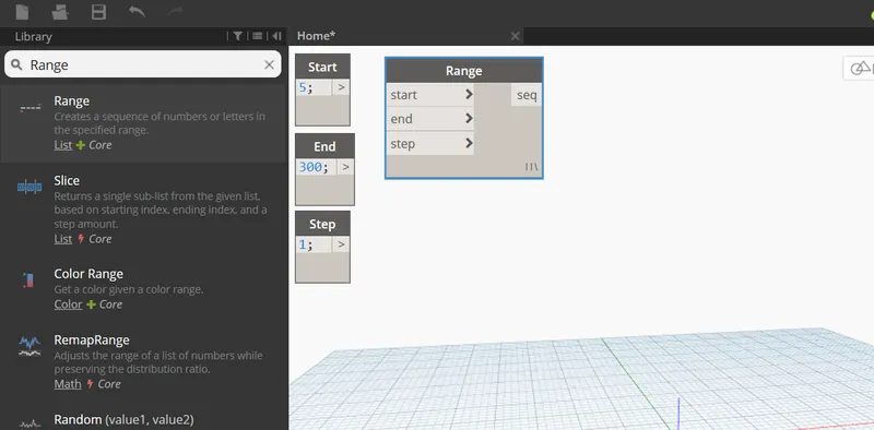
- Now,connect these three code block as input to the range block
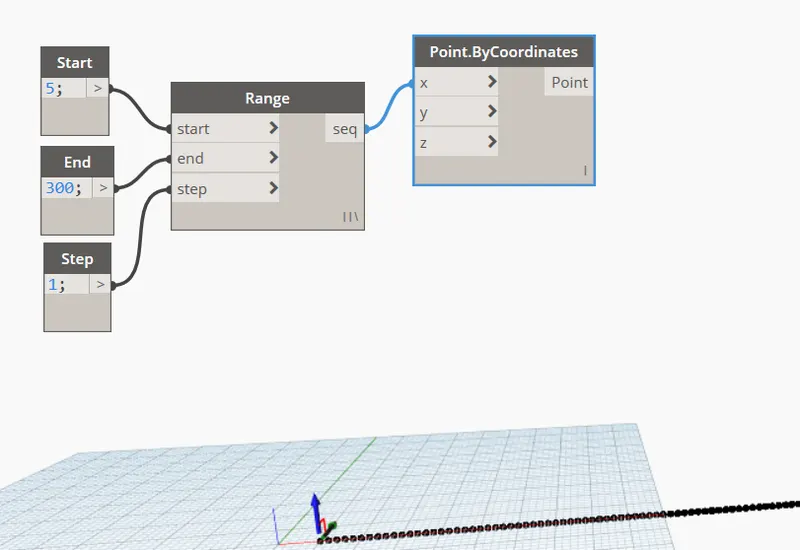
- Now, search point by coordinate in the search panel
- Then,connnect the range block to the coordinate of the point by coordinate block
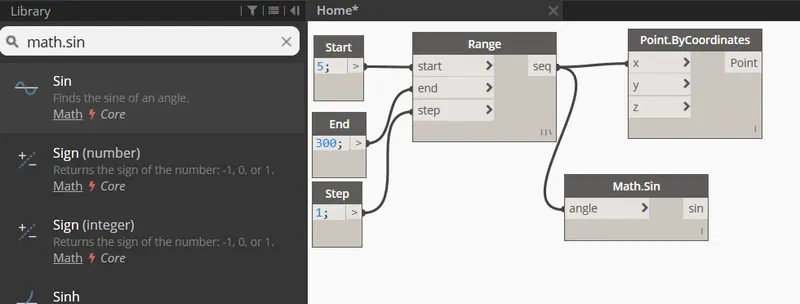
- Now ,we have to produce sin wave out of these point for which we have to insert sin functon which is given by math in the liabrary
- Sin values are very small so ,we need to amplify it,for this insert another integer slider and name it as amplifier
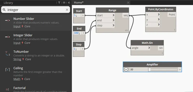
- This ,amplifier code block needs to be multiplied to the sin block
- FOr thismsearch product function in the liabrary
- Input for x value is sin block and for y value is amplifer
- Next,we have to provide phrase for the sin curve
- SO,again insert an integer slider and name it as phase
- Now,the phase block is then added to the amplified sin block
- FOr this insert add operator block from library
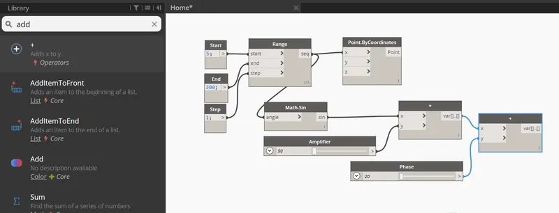
- Now this is then connected to the y coordinate of the point by coordinate block
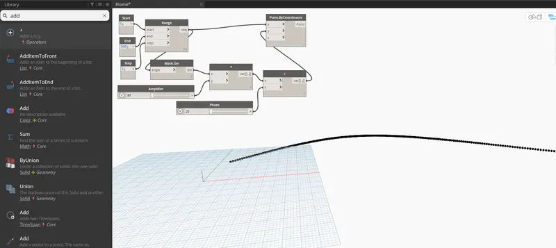
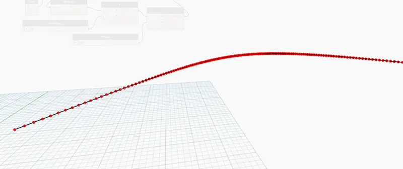
- Hence the set of sinusoidal points are obtained
- Now,we have to convert them to a curve
- The curve can be created from nurescurve
- Search nurbscure in liabrary and choose nurbs curve by control point
- Now,connect the point by coordinate block as input fot the nurbs curve ,A line will be devloped connecting the points
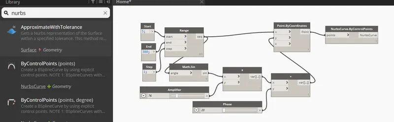
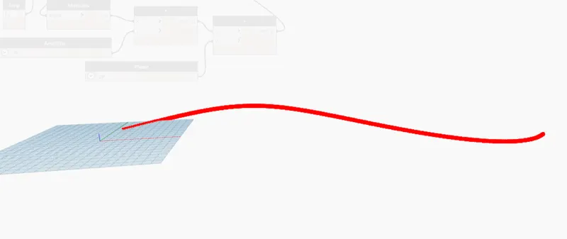
- Hence,the set of sinusoidal point are obtained
- Now,we have to convert them to a curve
- The vurve can be created from nurbcurve
- Search nurbcurve in liabrary and choose nurbs cirve by control points
- Now,connect the point by coordinate block as input for the nurbs curve.A line will be developed connecting the points
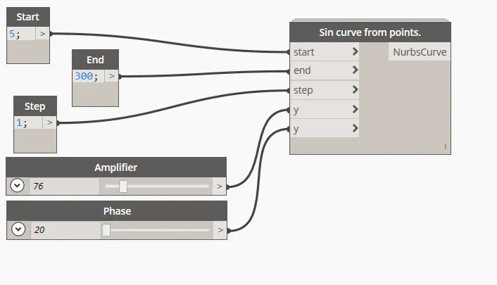
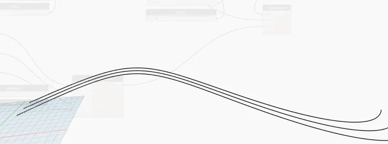
- Now copy this entire block two times to create the surface
- Adjust phase to view the two curves that is copied
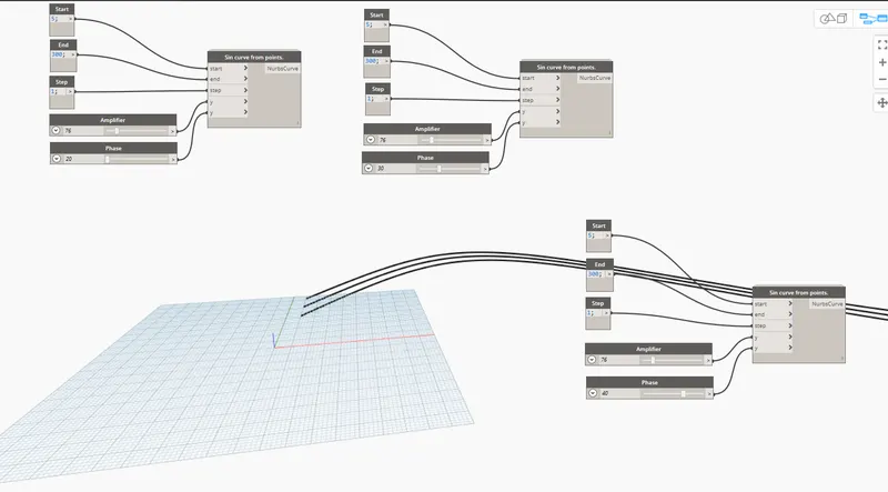
- Next step is to create the surface
- For this first create a list
- This can be done by seatching list.Create inn the search panel of liabrary
- This will servr as the input for the surface by loft block
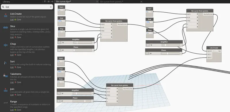
- Now we have to create the surface
- For this search surface by loft
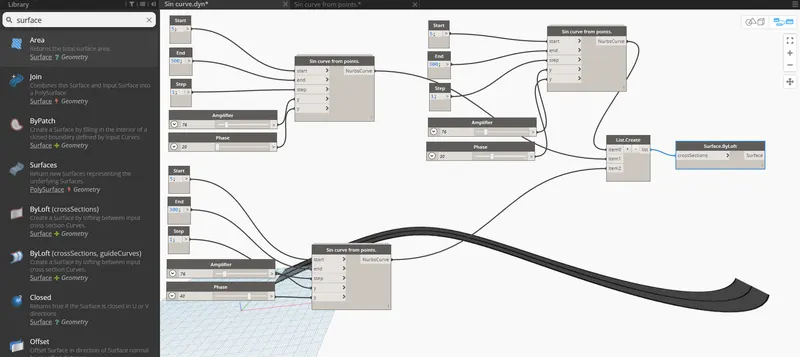
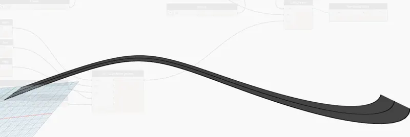
- Hence the surface is developed out of the curve
- RESULT
- A set of sinuisoidal points have been created as follows
- sinusoidal curve connecting points is developed as given below
- Surface is developed out of the curves as follows
2)
- AIM: To create a conceptual layout of a floor plan in dyanamo
- PROCEDURE:
- Open a new architectural template
- Go to manage and open the dynamo--->New
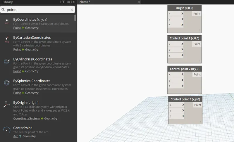
- Inorder to create the wall first we have to create four control points
- For this search points by coordination in the search panel of the liabrary
- First one is named as origin(0,0,0) and the rest isn named as control, point 1(x,0,0) control point 2(0,y,0)and control point3(x,y,0)
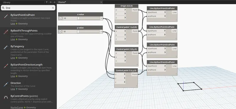
- Now,we have to connect these points bya line
- SO for this ,search line by start and end point and insert 4 blocks
- THe input for these blocks are the point created previously
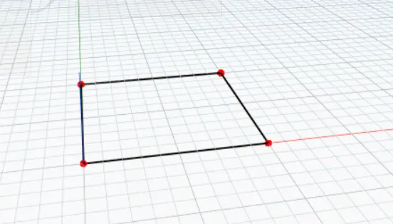
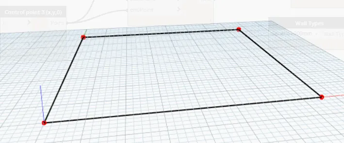
- Hence the layout of the floor plan is obtained
- Now,search the wall in the panel and choose wall by curve and height
- So,for this input required are curve height level and wall type ,input are given as follows
- FOr curve ,combine all the four lines in a list by choosing list create
- FOr height ,another number slider is choosen and name it as height
- FOr level search level in the searchg panel it will contain the level available in your revit Folder ,then choose the level in which you want to place your structure
- For wall type search wall type in the panel and it will display the wall types linked in the revit file
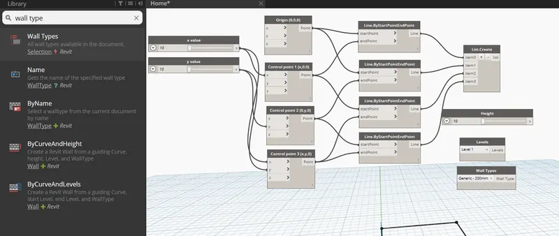
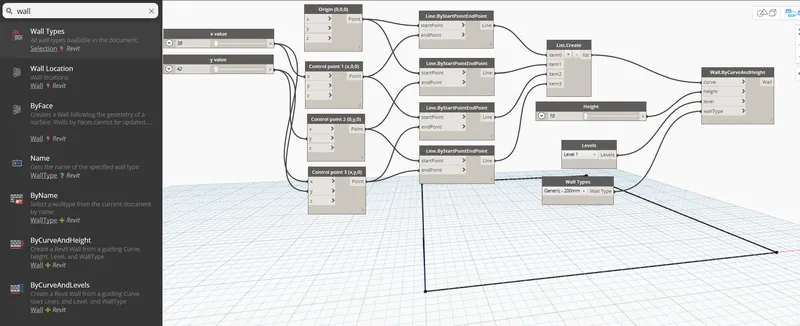
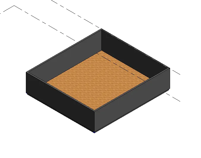
- The floor plan layout is given below
- Now,go to revit file to view the 3D formwhere the height of the wall is visible
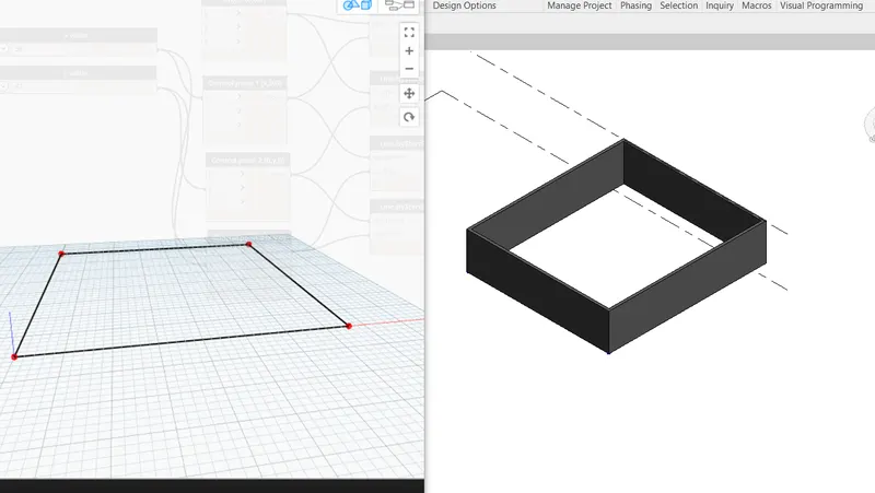
- The height of the wall can be adjusted using the slider
- Now,we have to place the floor
- For this type floor in the liabrary and select flootr by outliner,floor type and level
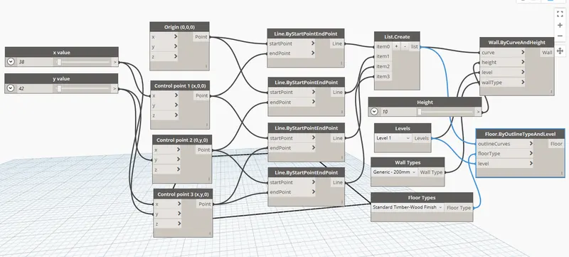
- This can be viewed in 3D view in revit file
- Result
- Hence the conceptual floor plan layout has been devloped and is as follows
- AIM: To create an array of model elements in revit
- PROCEDURE:
- Open a new architectural temmplate in revit file
- In that go to architectural tab---->columns ---->Architectural column---->Place the column
- Now,similarly 16 column are created

- The Properties of the model elements are varied using dynamo
- Now open dynamo
- In the search panel of the liabrary search select model elements integer ,slider and select and set rotation
- The integer slider is renamed as rotation angle
- Now select model elements block will be the input for family instances and integer slider will be input for degree
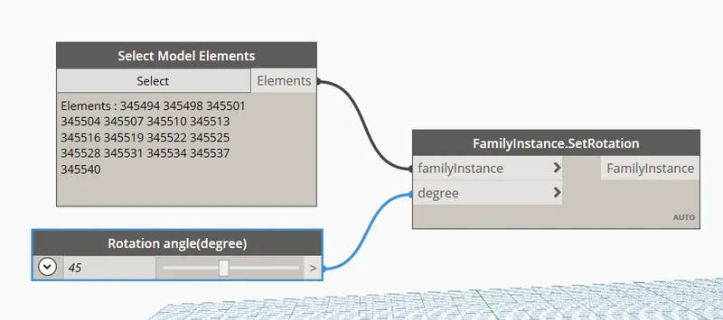
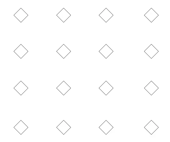
- The rotaion angle can be varied to desired value
- RESULT
- The array of model elements have been created and their properties are being variedthrough the blocks created in dynamo
- AIM: TO create a conceptual mass in revit and devlop a paramteric column by dividing the surfaces
- PROCEDURE:
- Open revit software and under the families open a new ---->conceptual mass--->mass
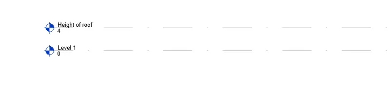
- Now ,go to elevation view and create view and create a level at 3,6mand name it as height of roof
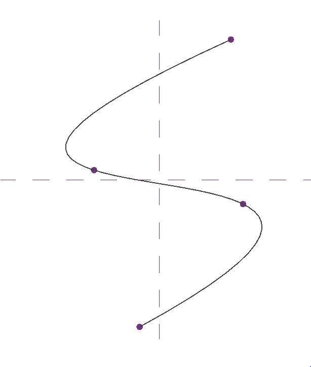
- Now using spline tool to draw the desired outline for the walkway
- Now,we have to create a profile to sweep thrpugh the curve
- For this,we have to set the workspace at the points and devlop a ppolygon at the workspace keeping the point at
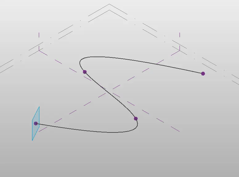
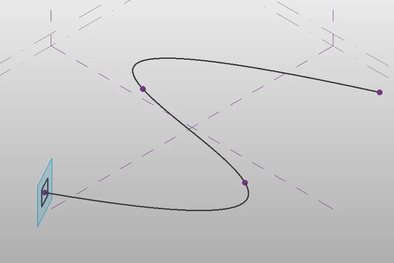
- Now a polgon is developed with point as centre
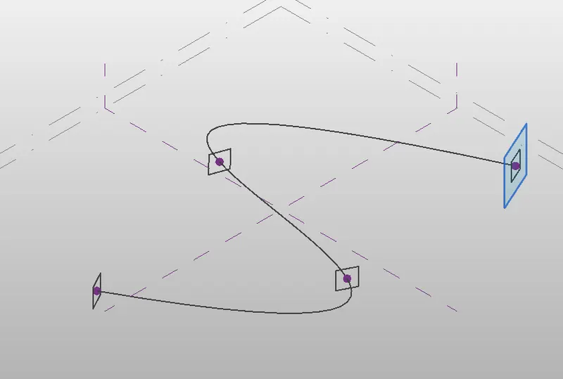
- Similarly workplane and polygon is developed at all nodes
- Now we have to create the surface which done through sweep
- For this ,select all the polygon and the curve line and choose create form option
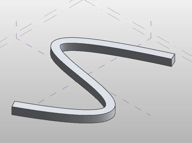
- Now select the entire form amd then filter and retain only the form
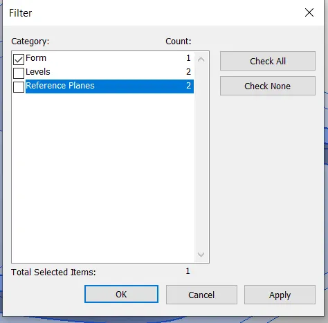
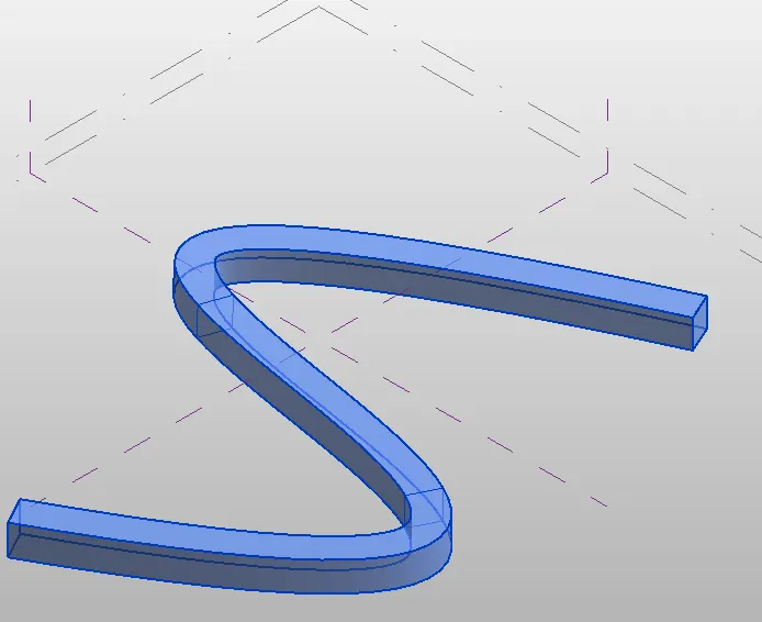
- Now select the form--->divide surface----->provide the pattern
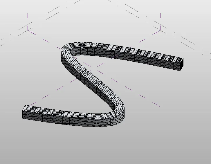
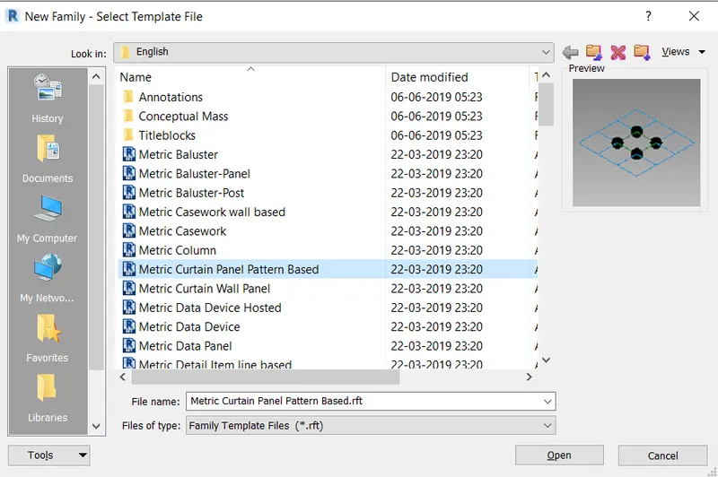
- Now open a new family ---->curtain panel pattern panel based
- Now,select the pattern as triangle bent
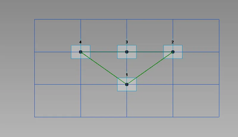
- Then create a reference point at the centre of the face
- Then draw a circle of radious 3" at that reference point
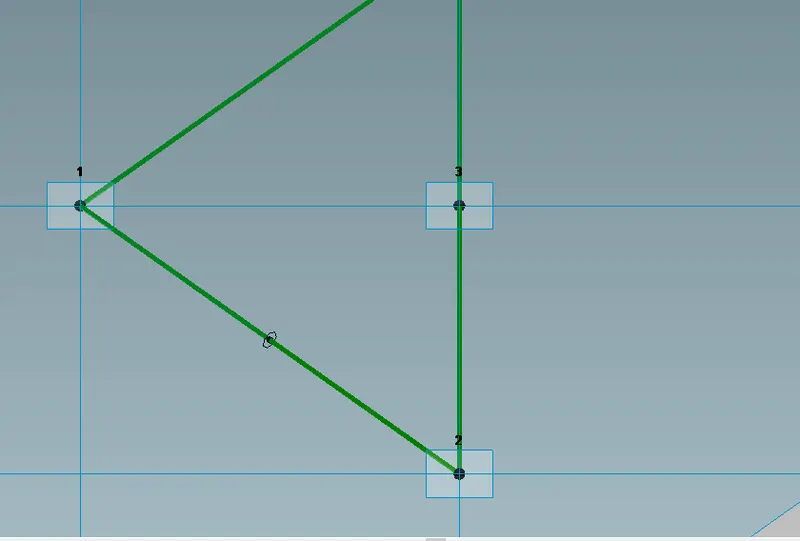
- Now select the patter,reference plane and circle created and choose create form
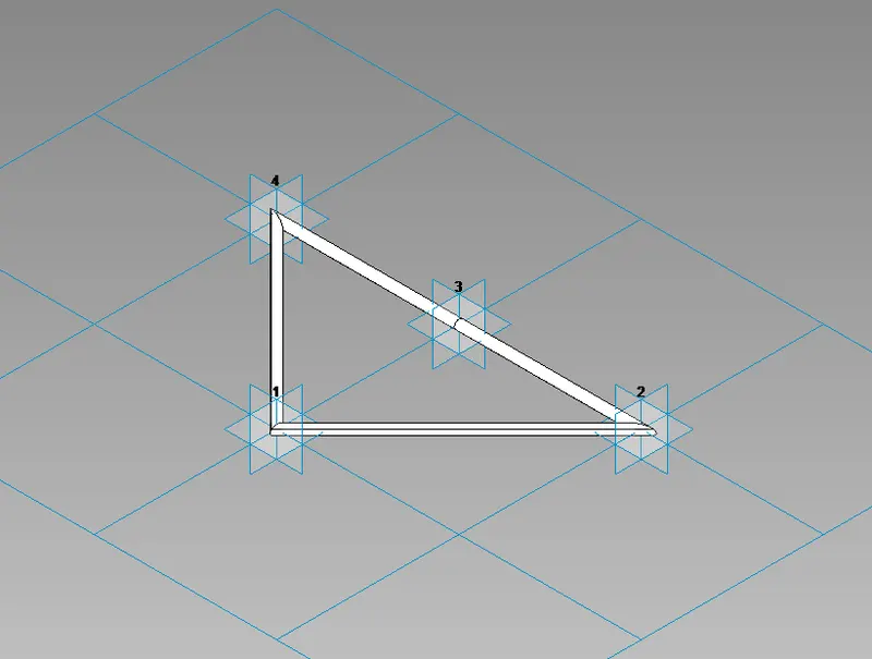
- Now load into project
- Now select the entire form of the walkway and filter it to retain only the divide surface
- Then in pattern select the family that we have created just now
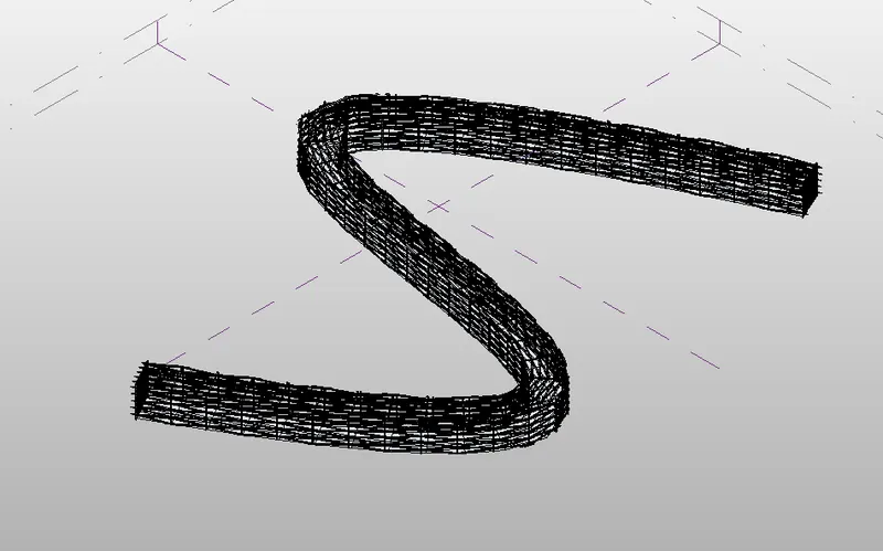
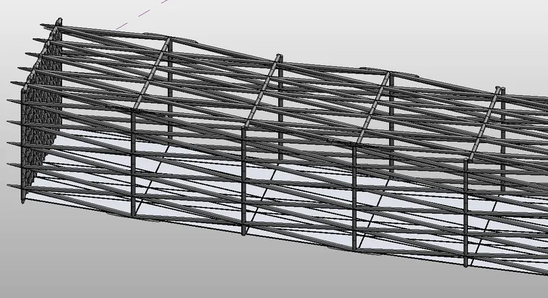
- Hence the conceptual mass have been created
- RESULT
- The conceptuaL mass have been created in revit amd is gioven as follows
- AIM: To devlop a parametric stadium usiung dynamo in revit
- PROCEDURE:
- Initially open a new architectural template in revit and then open dynamo
- Basic parametric to design a high rise structure created as input in dynamo
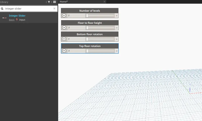
- Four integer slider is taken from the liabrary for the following
- Number of levels
- Floor to floor height
- Bottom floor rotation
- Top floor rotation
- Now search coordinate by origin in the liabrary and insert it
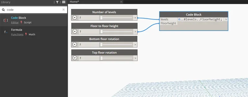
- Then connect the code block as input for z coordinate in the coordinate by origin block
- Now,search coordinate by origin in the liabrary and insert it
- Then connect the code block as input for z coordinate in the coordinate by origin block
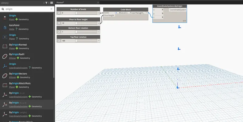
- Five points are generated coorresponding to 5 levels
- Now,insert rectangle by width and length from the liabrary
- FOr this ,input required are coordinate system ,length,and width
- So insert ,integer slider for length and width
- Then connect the input for the rectangle block
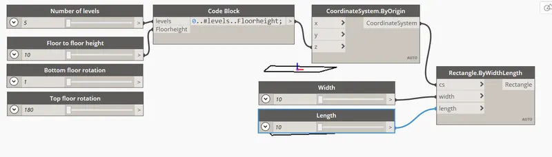
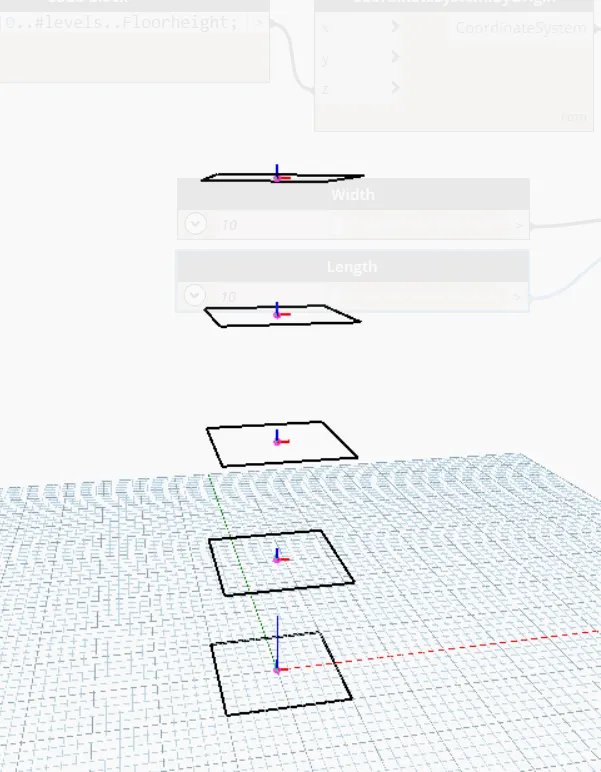
- Now we have to rotate geometry
- So,for this insert the rotate block from the liabrary .THe inputs required are
- Geometry ,rectangle block
- OPrigin,insert an origin block from the liabrary
- Axis :insert vector an origin block from the liabrary
- Degrres :fopr this insert a code block and type botoom.Top level .The inputs for this code block is already availabel i.e .Bottom floor rotation ,Top floor rotation and levels
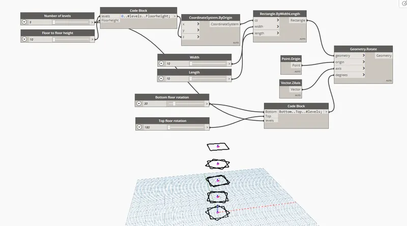
- Now we have to create surface for this type surface by loft in liabrary
- Then connect geometry rotate block as input for surface by loft
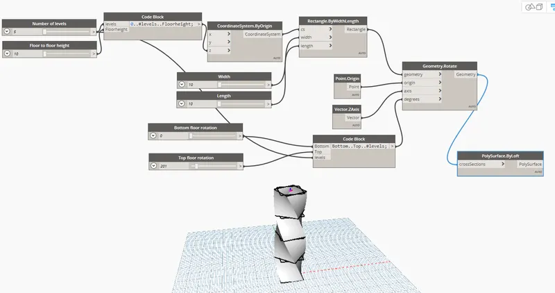
- Hence parametric stadium have been created
- The number of levels and width and length of the rectangle can variewd accordingly
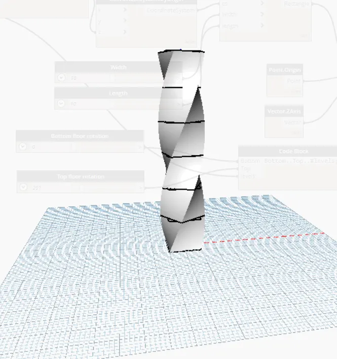
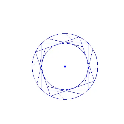
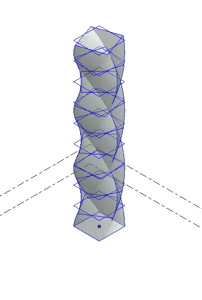
- In revit structure is visible as follows
- RESULT
- Hence parametric stadium have been created and is given below