Creating Conceptual mass in REVIT and Creation of Sinusoidal curve and a Parametric stadium using Dynamo
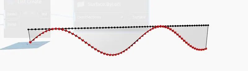
AIM-1: Using Dynamo create a set of sinusoidal points and create a curve and create a surface out of the curve.
INTRADUCTION:Dynamo is an open source visual programming language for Revit, written by designers and construction professionals. It is a programming language that allows you to type lines of code; while also creating an algorithm that consists of nodes.
PROCEDURE:
- Open the revit application then go to manager tab then click on the dynamo icon right-up corner then it opens

- then dynamo working screen is appeared then click on the new working screen is appeared
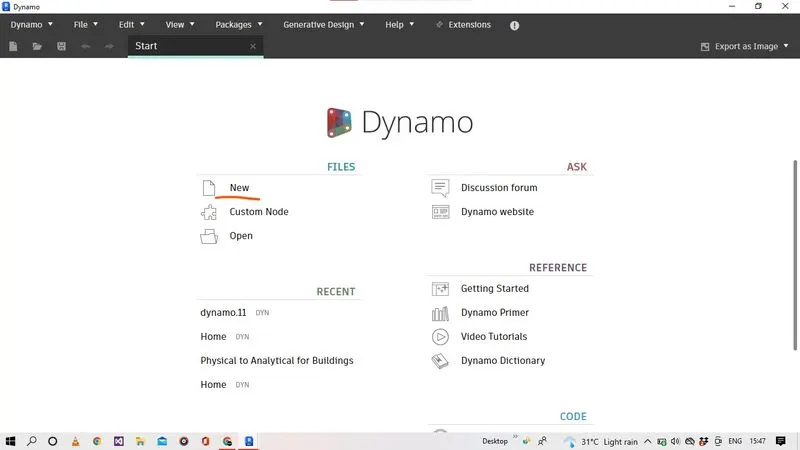
- go to the new icon to created new file created thenwe go to dynamo working screen
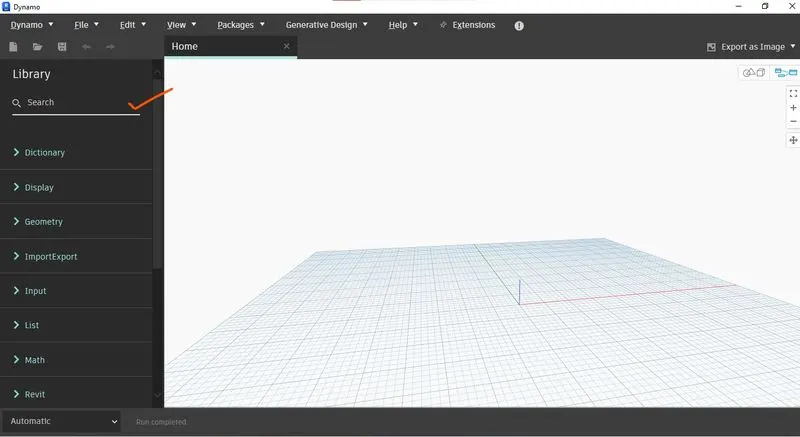
- left side of the working screen visuvalization tools bar appeared
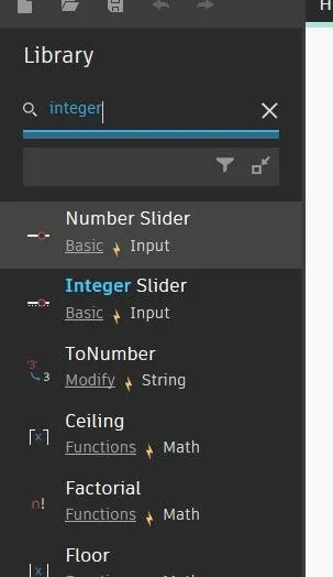
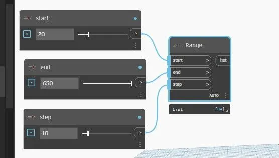
- then search for integer slider add to the screen then click control+drag that slider icon another opy is created we have to create the 3 sliders
- then make a changes a we required
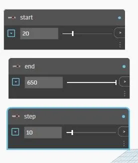
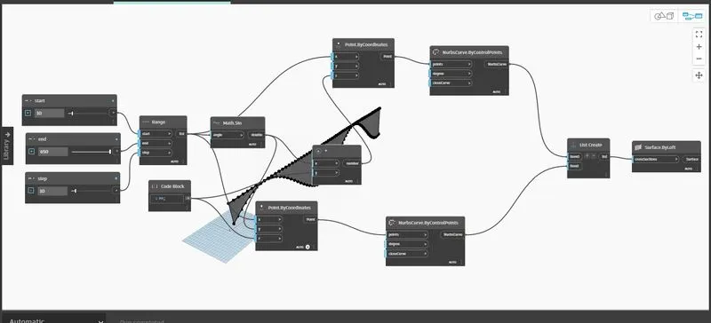
- we search for range tool in search bar
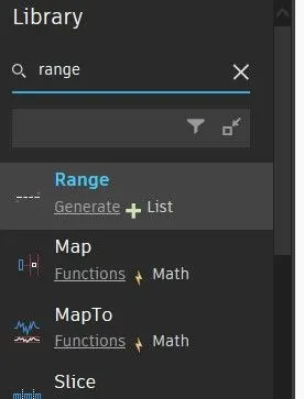
- then we get the range icon containing 3 points inward
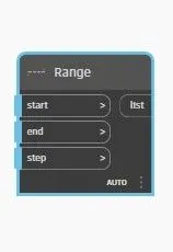
- then we connnect to the those 3 sliders start,end and step points
- then we serch for poin.by coordnate add to the screen
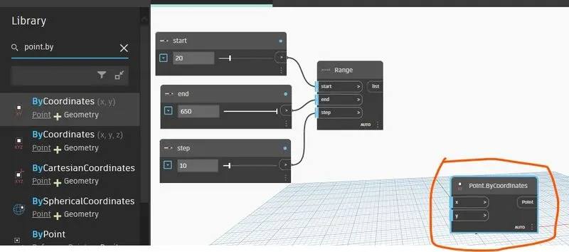
- then another point.by coordinate icon and code is created for the perpose of synatical curve then search for math.sin and add to working screen
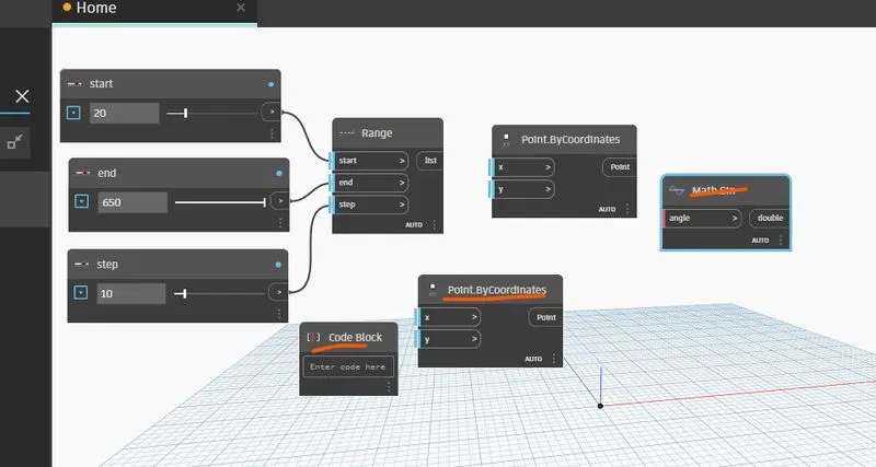
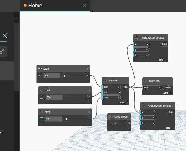
- then we connect range icon tool to the point by coordinate X axies another math function icon and to another coordinate x axies.
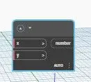
- then we seach for a product tool icon add to the screen
- then code block is connected to the point by coordinate in z axies and math.sin to y axies in coordinate.
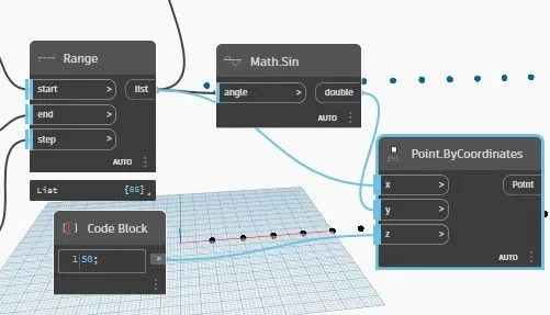
- then we have to connect the math to product X axies and codeblock connect to Y axies in product then after that product connect to point.by coordinate Z axies then we pramatrical order wave shape points created.
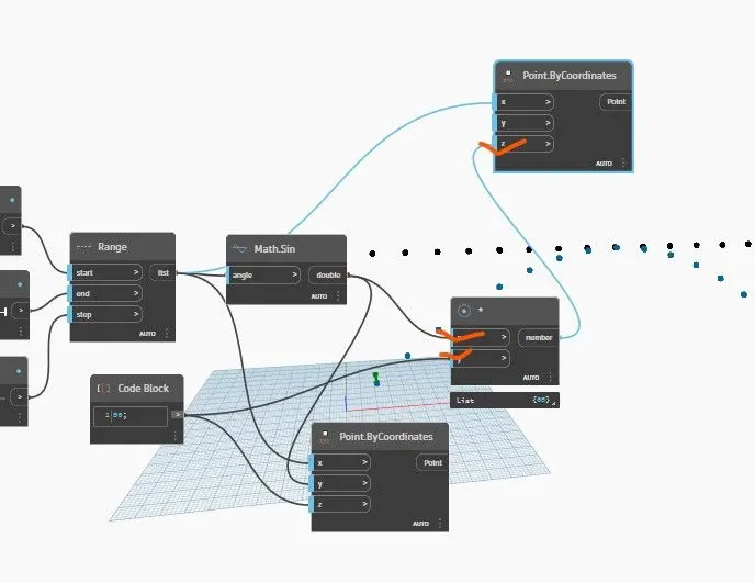
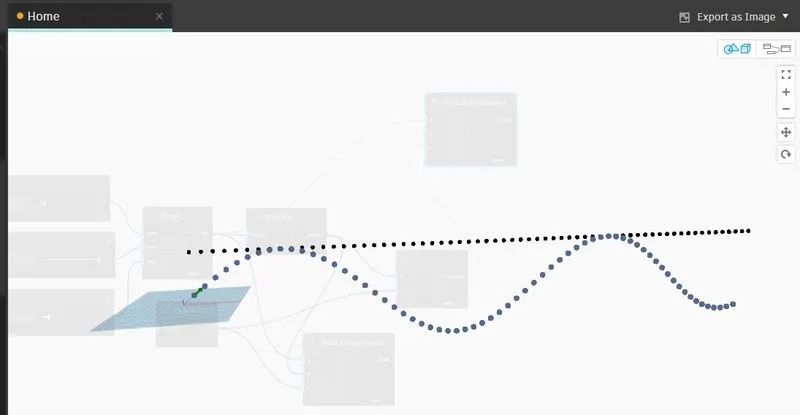
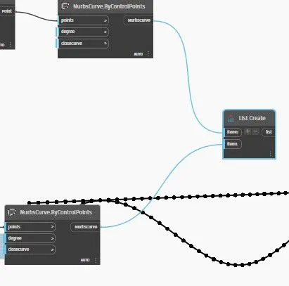
- no we have to add nurbcurvetool icons twice to working screen.
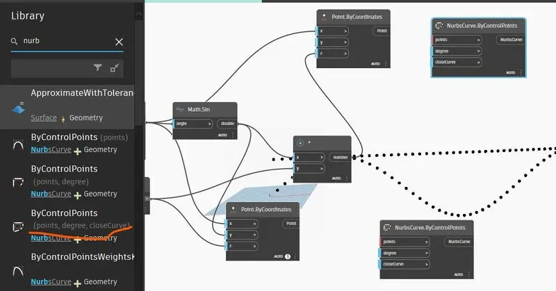
- ten add those two coordinate points to nurbcurve tools to lines created
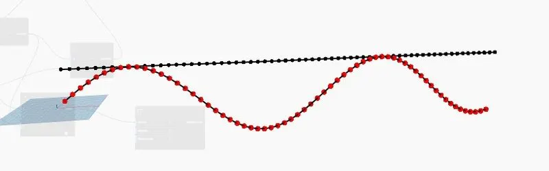
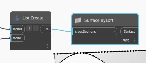
- then we another tool to the sceen is that one list. then those two nubcurve icons connect to the list
- then we add surface to the curves by the icon tool is sufacebycrosssectionby loft add fro search bar then those list icon connect to this surface tool icon
RESULTS;
AIM-2; Create a conceptual layout of floor plan in dynamo . Using the tools available in dynamo link the lines to appropriate model elements in Revit by choosing the wall types and wall parameters. Make use of the sliders to slide through the height of the wall and length of the wall.
INTRADUCTION:Dynamo is an open source visual programming language for Revit, written by designers and construction professionals. It is a programming language that allows you to type lines of code; while also creating an algorithm that consists of nodes.
PROCEDURE:
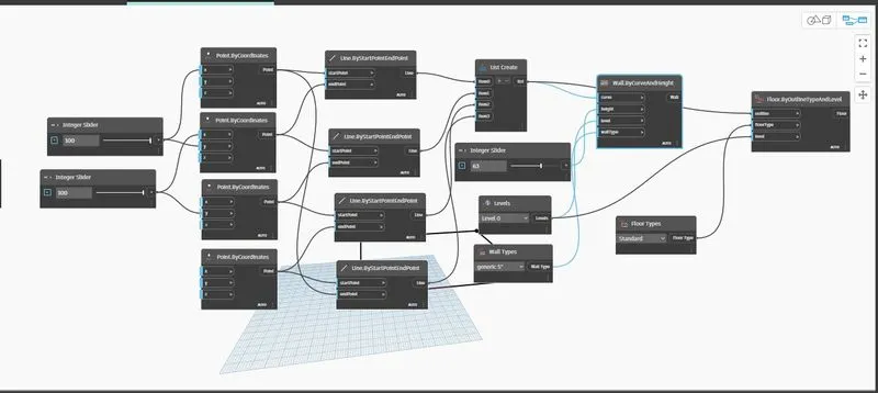
- open the new file in te dynamo then add 2 integer sliders and 4 coordinate points tool icons created
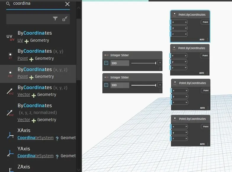
- then integer slider add to 1 coordinate point X axies
- then 1st integer slider add to 2 coordinate poit Y axies
- after 2nd integet slider connect to 2 coordinate point X axies
- after 2nd integer slider connect to 3rd coordinate points Y axies
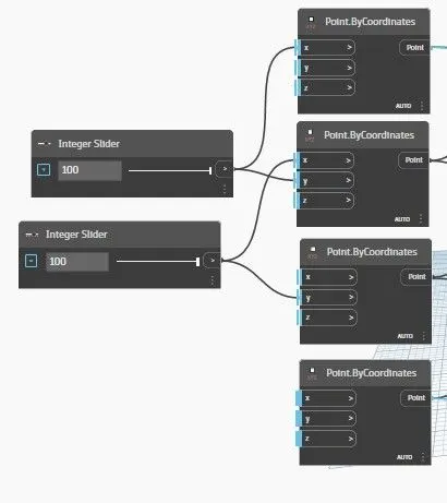
- now we have to create 4-line tool icons
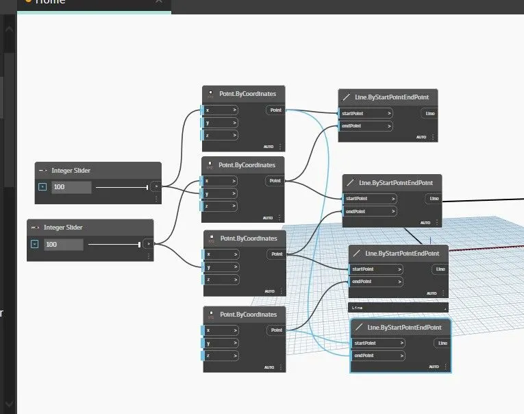
- now we have to conect to the
- 1st point by coordinate connect to the 1st line tool start point then 1st coordinate point connect to the last 4th line endpoint
- 2nd coordinate point to connect 1st line tool end point and 2nd coordinate point conect to the 2nd line tool icon start point
- 3rd coordinate point to connect to 2nd line tool icon end point and 3rd coordinate point connect to 3rd tool start point
- 4th coordinate point to connect to 3rd line tool end point and 4th cooordinate point connect to start point of 4the line tool point.
- then we check model screen in dynamo rectangle lines are created or not.
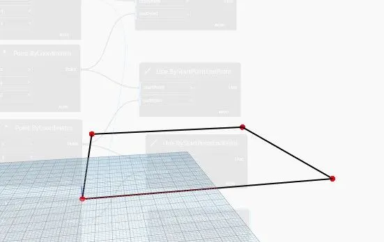
- add those lines to list tool
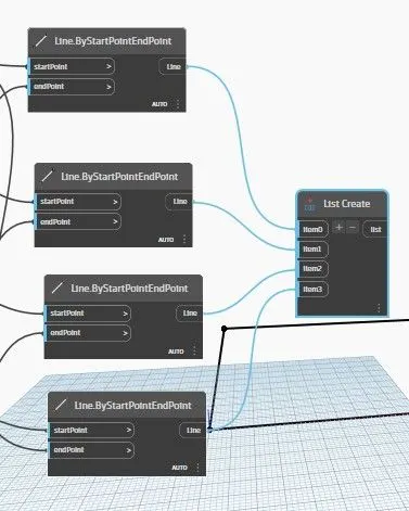
- then add list tool ,integer slider,levels and wall types to screen.
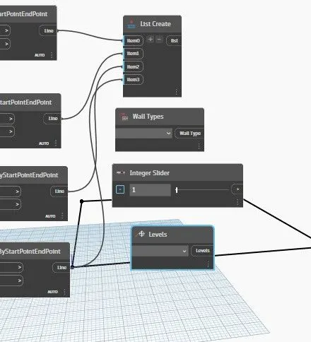
- set require elements to be created as per require
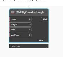
- add those elements to wallbycurveandheight
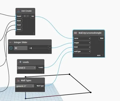
- then wall are created in dynamo and also height is adjusted by integer slider which we provided
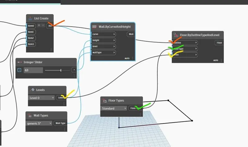
- and floor type tool is created add to screen and another floor type outlettool ico is created and these elements are join this floor.byoutlinetypeandlevel.
RESULTS:
AIM-3: Create an array of model elements in Revit. Use dynamo to vary the properties of model elements by using the slider or code block
INTRADUCTION:Dynamo is an open source visual programming language for Revit, written by designers and construction professionals. It is a programming language that allows you to type lines of code; while also creating an algorithm that consists of nodes.
PROCEDURE:
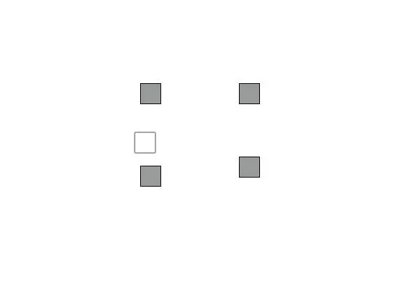
- Open the revit application and create four columns in working screen
- then go to the dynamo by go to manger tab click on the dynamo icon
- dynamo working screen appeared
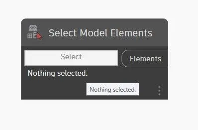
- then add selectelement model icon to transfer the already created revit element to select
- then we have to add rotation tool instance to rotate the element
- rotation element contain familyinstance and degrees
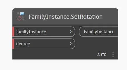
- then we have to add integer slider to adjust rotation
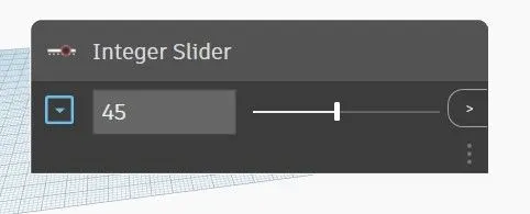
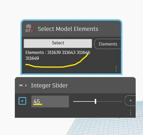
- after that these integer slider add 45 degree value and click on the slect icon in select modelelement tool
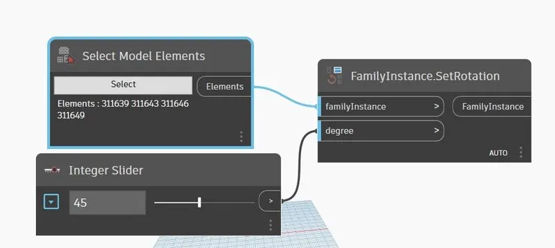
- then these elements means integer slide, select model elements connect to familyinstance.setrotation.
RESULTS:
AIM-4: Create a conceptual mass in Revit and develop a parametric column by dividing the surfaces and apply the concepts similar to used in parametric walkway modelling. Use triangular bent or square shaped panels to add finish to the parametric column.
INTRADUCTION:Dynamo is an open source visual programming language for Revit, written by designers and construction professionals. It is a programming language that allows you to type lines of code; while also creating an algorithm that consists of nodes.
PROCEDURE:
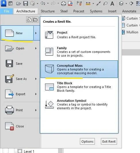
- Open the revit application then go to file menu click on the new then select conceptual mass
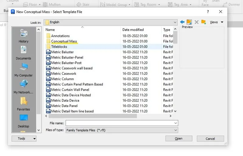
- then we get another dailog box related go to conceptual mass icon.
- then we get conceptual mass layout appeared then we have to select
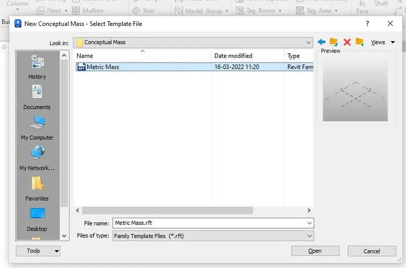
- then we get appeared conceptual mass editing and layout is created with in buld tools involved what we required
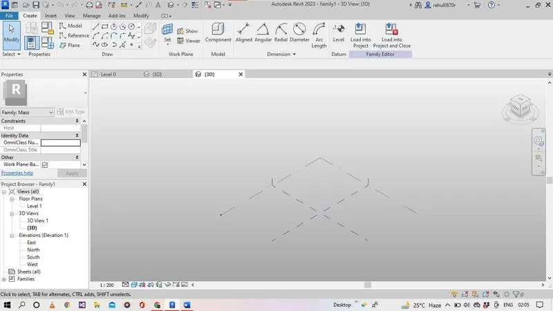
- then we go to elevation view from project browcer
- then select picline option and multiple the level add another one
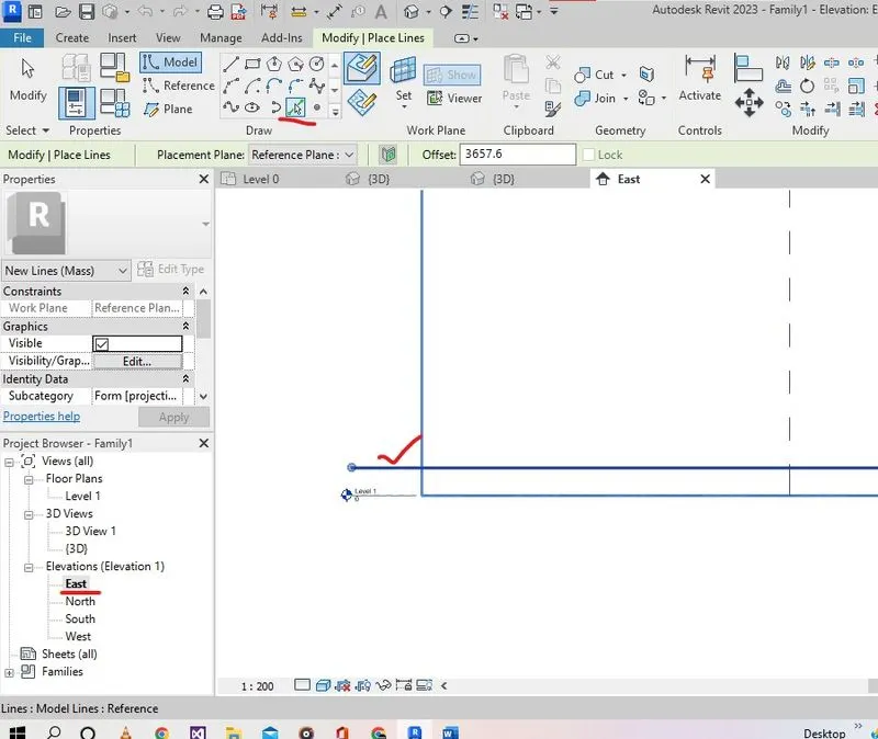
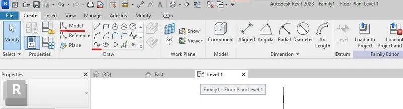
- then have go to create tab menu and then select model line tool then select spline option then draw the require shape
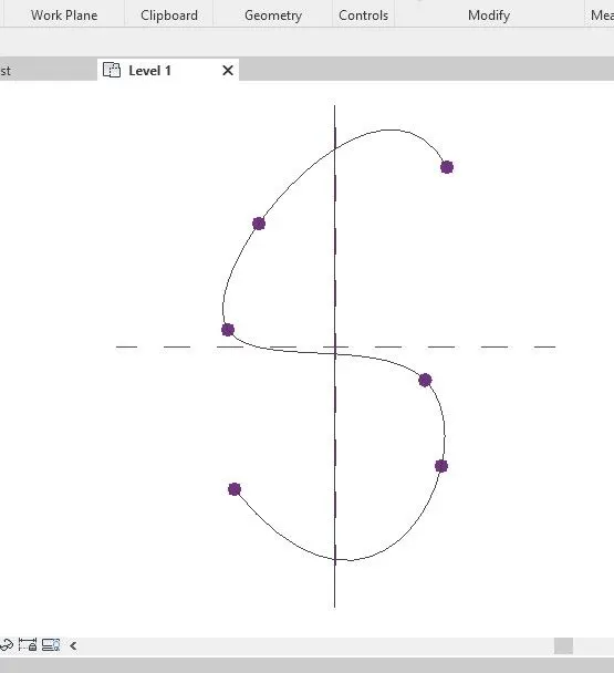
- then go create tab and then select setplane icon after that click on the show plane option to plane created APPEARE
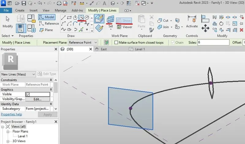
- then select polygon tool select point in spline create poly through a plane with range off 12'
- repeate this whole process to every point spline
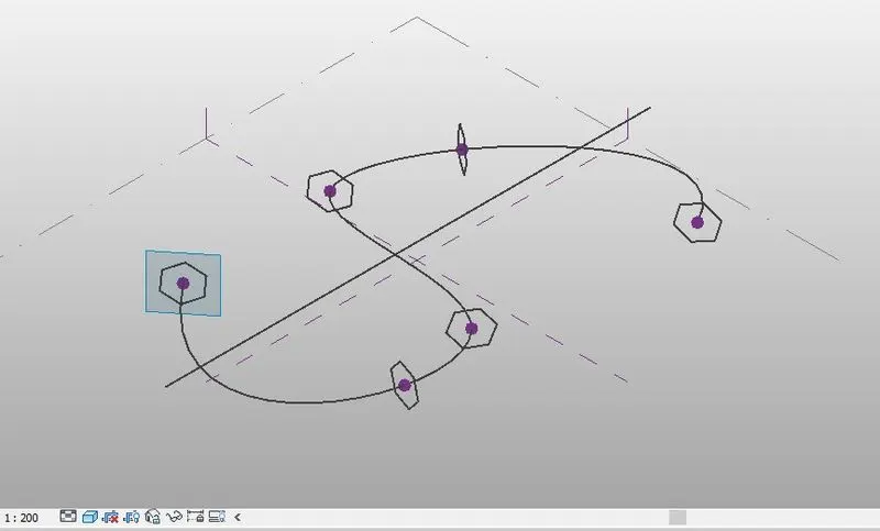
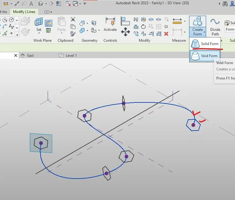
- then we have select curve and polygon at atime then appeared create form icon in tan click on that and select solid icon to select solid form is created
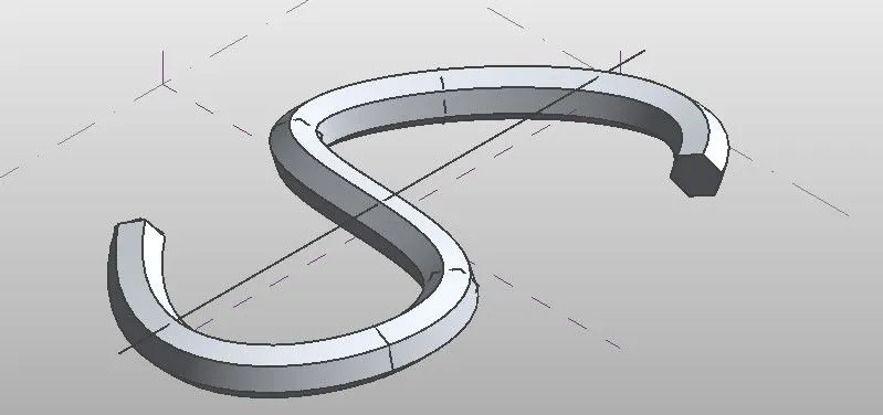
- then we have select only surface then select divide surface option appeared in tab select that
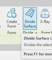
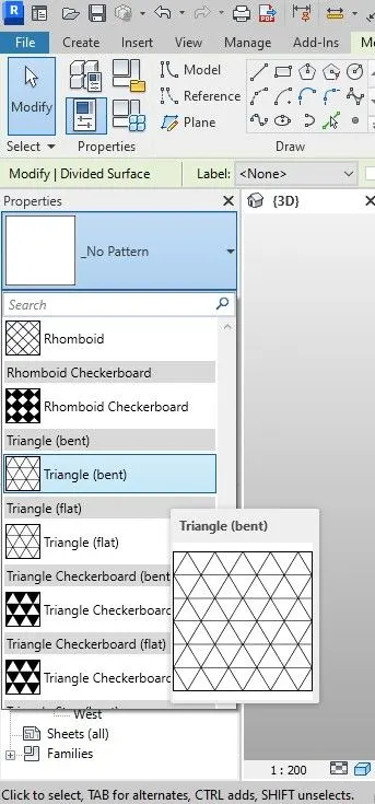
- the we go to the propeties browcer we multiple rooling titles appeared then related surface patterns we have select triangler bent option as mention in given aim.
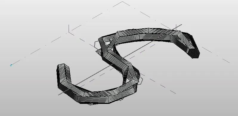
RESULTS:
AIM-5: Use Dynamo to work on developing a Parametric Stadium. List your parameters and use the visual programming approach to complete the modelling, You can use the concepts discussed in parametric high rise tower in class for reference.
INTRADUCTION:Dynamo is an open source visual programming language for Revit, written by designers and construction professionals. It is a programming language that allows you to type lines of code; while also creating an algorithm that consists of nodes.
PROCEDURE:
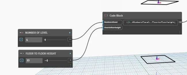
- open the dyanamo new file then add 2 integer slider tools
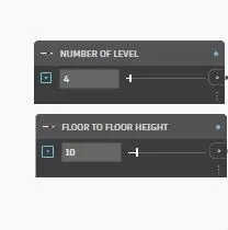
- and then addcode balock and write some code
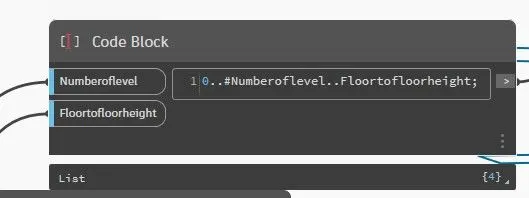
- then these integer slider conect to the code block as per code we mention names on ther integer sliders
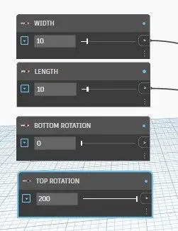
- then we have another 4 integer sliders for width,length, bottom rottation and top rotation angle
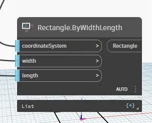
- then add the rectangle tool icon mention in width, length and coordinate system
- then we add the coordinates icon mention in x,y and z
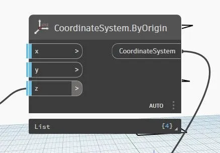
- after that code block is connected to the coordinate system by origion icon in z axies
- integer sliders width and length added to the rectangle icon then coordinate system in by origin is connected to the rectangle tool block
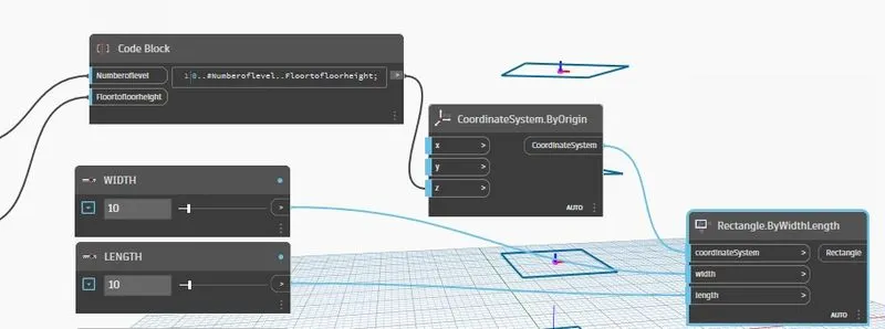
- then add the Z axies, poin.origin and geometry,rotate tools are added
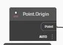
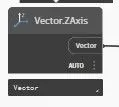
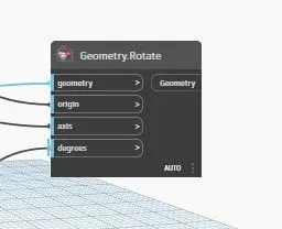
- these rectangle added to the geometry
- point.origin added to origin
- vectorz-axies added to theaxies in geometry.rotate
- code block added to the degrees
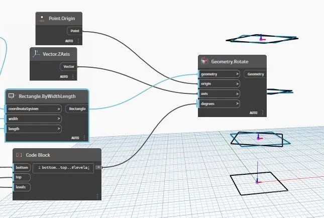
- in background the planes are created what we details we provided
- then we added another tool ico polysurface by loft
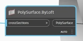
- then we wanted stracture created as mention inthe aim.
RESULTS:
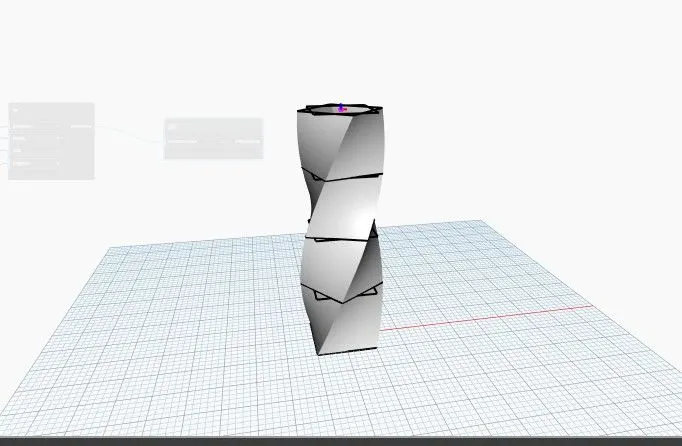
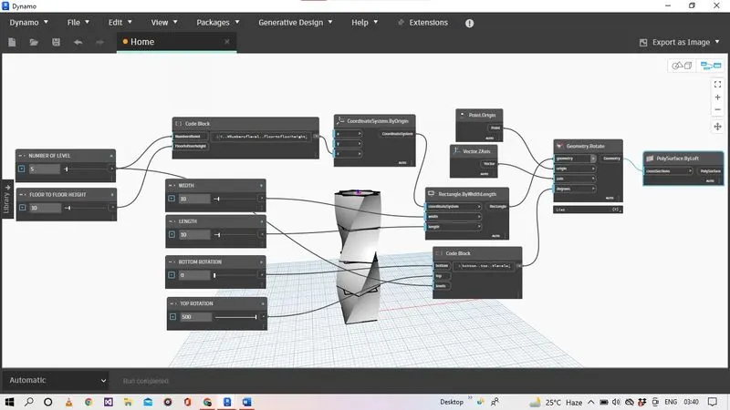
THOSE SLIDERS HELP US TO CHANGE FLOORS AND ROTATION ANGLES FLOOR TOFLOOR DISTANCES INSTANTLY.