Creating Conceptual mass in REVIT and Creation of Sinusoidal curve and a Parametric stadium using Dynamo
1) Using Dynamo create a set of sinusoidal points and create a curve and create a surface out of the curve.
Ans:-
Aim:- To create a set of sinusoidal points and create a curve and create a surface out of the curve Using Dynamo
Procedure:-
Open Dynamo;
integerslider(3no.s) i,ii,iii by using copy paste options.
set those values ranges as 12,650,10 simultaneously.
Range; by start end setup
connect i to start range
connect ii to end
connect iii to step.
point;by coordinates xyz
codeblock-50
point by coordinates;
Math.sin;sin;Angle Double
connect angle to X (then we will get points on dynamo work space)
connect range list to Math.sin angle.
Range.list to point by coordinates X axis
product;*;
(connect the codeblock to z point by coordinate iii
connect Math.sin to y
math sin to * x
code block to * y
* varient to point by coordinates i -z
Nurbs;by control points;points degree (2no.s)
list;listcreate
point by coordinates i to Nurbs curve points i
point by coordinates ii to nurbs curve points ii
nurbs curve i to list create item i
nurbs curve ii to list create item ii
surface;By loft (cross section)
connect create item to loft cross section.
All the above procedure shown below;
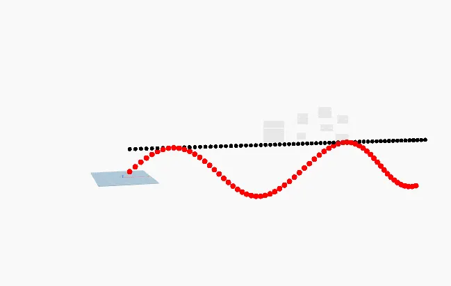
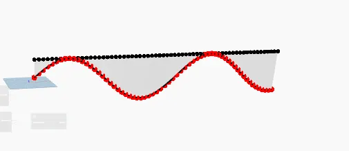
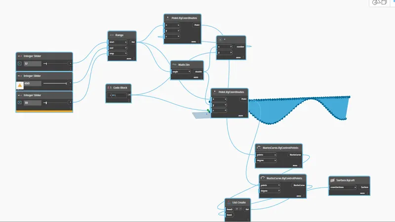
Result:- finally i got to know about how to craete points and surface of sinusoidal by using Dynamo.
2) Create a conceptual layout of floor plan in dynamo . Using the tools available in dynamo link the lines to appropriate model elements in Revit by choosing the wall types and wall parameters. Make use of the sliders to slide through the height of the wall and length of the wall.
Aim:- To Create a conceptual layout of floor plan in dynamo . Using the tools available in dynamo link the lines to appropriate model elements in Revit by choosing the wall types and wall parameters. Make use of the sliders to slide through the height of the wall and length of the wall by using Revit.
Procedure:-
open dynamo;
integerslider (2no.s) make them 100
poine;by coordinates (4no.s)
connect first integer slider to 2nd point by coordinate y.
connect second integer slider to 2nd point by coordinate x.
connect 2nd integer slider to 3rd point by coordinate y.
line;by start point end point (4no.s)
connect 1st point to start line first.
connect 2nd point to 1st line end point.
connect 1st point to last line end point.
connect 2nd point to 2nd start point
connect 3rd point to 2nd end point
connect 3rd point to 3rd start point
connect 4th point to 3rd end point
connect 4th point to 4th start point
cross check it in revit.
list;list create;4drop downs
1st line to item 0
2nd line to item 1
3rd line to item 2
4th line to item 3
level;
wall types;
integer slider;
choose level as level
wall type (select suitable)
integer slider;set it as 10
wall;by curve and height
connect list create to curve
connect level to level
connect wall type to wall type
connect integer slider to height
floor;floortypes;choose suitable
floor;by outline type & level
connect list create to outline curves
floor type to floor type
level to level
To cross check it open in Revit.
The procedure is shown in figure below.
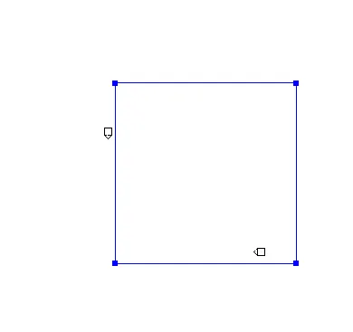
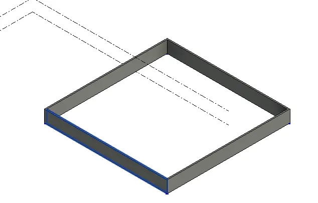
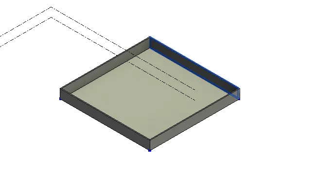
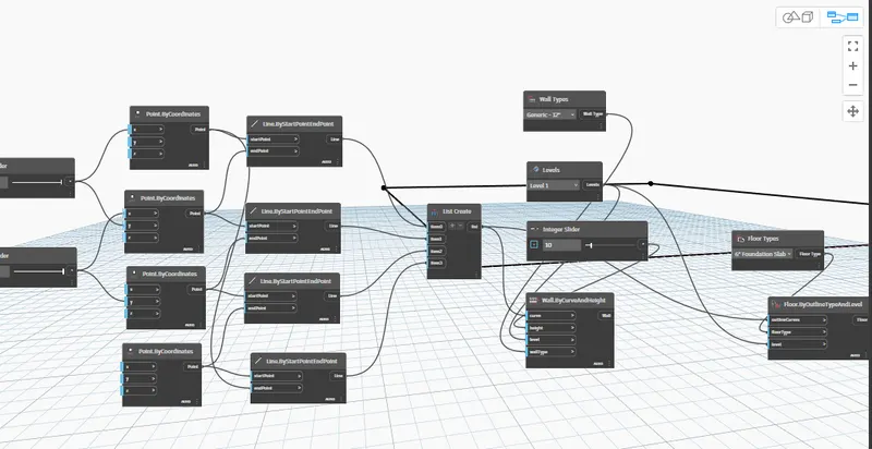
Result:- Finally i got to know about how to create a room by using Revit.
3) Create an array of model elements in Revit. Use dynamo to vary the properties of model elements by using the slider or code block
Aim:- To Create an array of model elements in Revit. Use dynamo to vary the properties of model elements by using the slider or code block
Procedure:-
(note:- this is only applicable for architectural elements)
open Revit;
Architectural column;
place 4 columns.
open dynamo;
Model;
select model elements(multiple)
rotation;
family instances;
integer slider;
model;
select option go to revit copy elemens(4columns) from Revit.
connect model elements to family instance
integer slider to degree (increase the number in integer slider)
open revit; select all components then they will visible in model.
the procedure is as shown below.
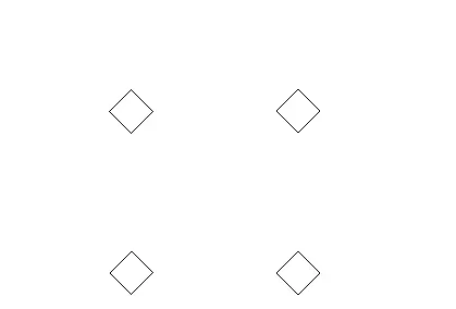
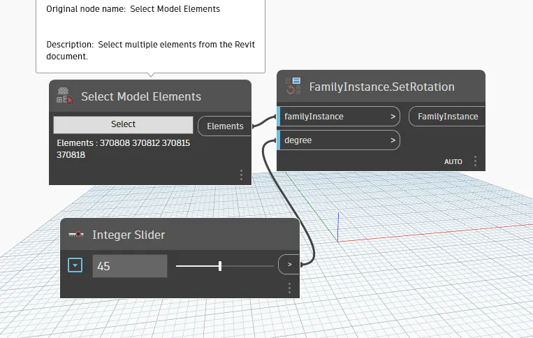
4) Create a conceptual mass in Revit and develop a parametric column by dividing the surfaces and apply the concepts similar to used in parametric walkway modelling. Use triangular bent or square shaped panels to add finish to the parametric column
Aim:- To Create a conceptual mass in Revit and develop a parametric column by dividing the surfaces and apply the concepts similar to used in parametric walkway modelling. Use triangular bent or square shaped panels to add finish to the parametric column
Procedure:-
Open Revit;
File;
new;
conceptual mass;
metric mass;
open;
Go to elevation east.
click on level;
pick line;
offset;
one more level will create
Go to floor plan;
create;
model;
spline;
go to 3d view;set;show by clicking on spline points.
choose circumscribed polygon and place it at some height on points at some distance.
create;
click on spline;
create form by selecting points and spline.
select all;
goto filter;
untick all except form only;
select all;
divide surface;
choose property from property browser ;
select triangle bent.
procedure as shown below;
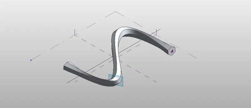
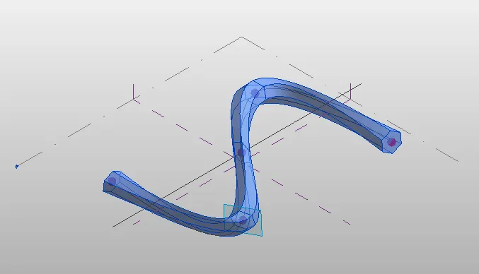
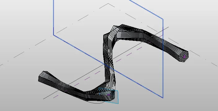
Result:- Finally i got to know about how to create walk way by using revit.
5) Use Dynamo to work on developing a Parametric Stadium. List your parameters and use the visual programming approach to complete the modelling, You can use the concepts discussed in parametric high rise tower in class for reference.
Aim:- To create multistorey building by using dynamo.
Procedure;-
open dynamo;
integer slider (2no.s) i,ii
i) no .of levels;level as 5
ii) floor height:height as 10
code block;0..#levels..floorheight
connect level to level
floor to floor height
origin;by origin xyz
connect codeblock to by origin z
integer slider;4 no.s
i) width ;10
ii) length; 10
iii) bottom floor rotation ; 0
iv) top floor rotation ;200
rectangle;
y width length;.coordinate system;
connect coordinate system to cs
width to width-i
length to length-ii
code block;
bottom..top..#levels
connect bottom floor bottom to bottom
connect top floor rotation to top
connect no.of levels to levels
point;by coordinate system
origin;by origin(coordinate system)
connect to code block z point by coordinate
connect to code block z point by coordinate system by origin
integer slider;(4 no.s)
width;10
length;10
top floor rotation;200
bottom floor rotation;0
rectangle;by width length (coordinate system)
coordiante system to CS
length to length by integer slider
width to width by integer slider
code block;bottom..top..#levels
connect
top rotation- top
bottom rotation-bottom
number of levels to code block levels
origin;point
vector;vector z axis;z axi
geometry rotate; rotate geometry(origin,axis,degree)
connect rectangle to geometry
connect point origin to origin
connect vector to z axis
connect degree to code block
poly surface; by loft
connect geometry to cross section.
the procedure as shown below.
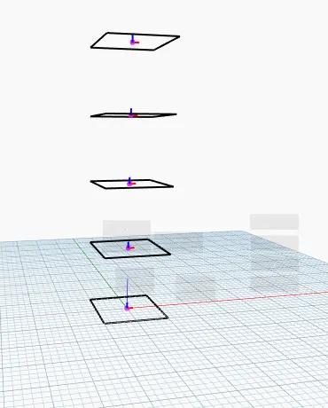
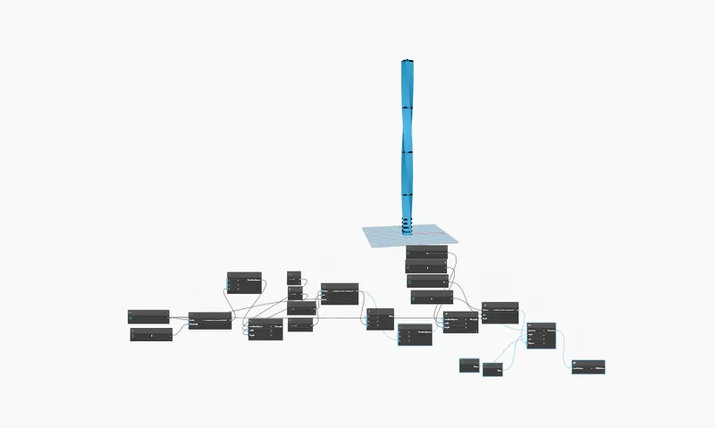 .
.
Result:- Finally i got to know about how to create building by using dynamo.