Creating Conceptual mass in REVIT and Creation of Sinusoidal curve and a Parametric stadium using Dynamo
1) Using Dynamo create a set of sinusoidal points and create a curve and create a surface out of the curve.
AIM:
To create a set of sinusoidal points and create a curve and create a surface out of the curve using dynamo
INTRODUCTION:
Dynamo is an open source visual programming language for Revit, written by designers and construction professionals. It is a programming language that allows you to type lines of code; while also creating an algorithm that consists of nodes.
Establishing visual, systemic, and geometric relationships between the different parts of a drawing is key to the design process. Workflows influence these relationships from the concept stage to final design. Similarly, programming allows us to establish a workflow, but through formalizing algorithms. Using Dynamo, you can work with enhanced BIM capabilities in Revit. Dynamo and Revit together can be utilized to model and analyze complex geometries, automate repetitive processes, minimize human error, and export data to Excel files and other file-types not typically supported by Revit. Dynamo can make the design process more efficient, with an intuitive interface and many pre-made scripting libraries available as well.
The user interface for Dynamo is organized into five main areas, the largest being the workspace where programs are processed. The user interface sections include:
• Main menu
• Toolbar
• Library
• Workspace*
• Execution bar
The workspace is the place where designers develop visual programs, but it is also the place where any elaborate geometry is previewed. Whether you are working in a home workspace or in a custom node, you can navigate the workspace by using the mouse or buttons on the top right. However, we can change the navigation preview by switching from one mode to another in the lower right.
PROCEDURE:
Intially open the architectural template of REVIT software and go to the manage tab
In manage tab select the dynamo , then dynamo window opens and then go to the new option
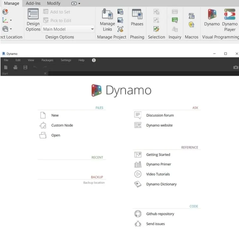
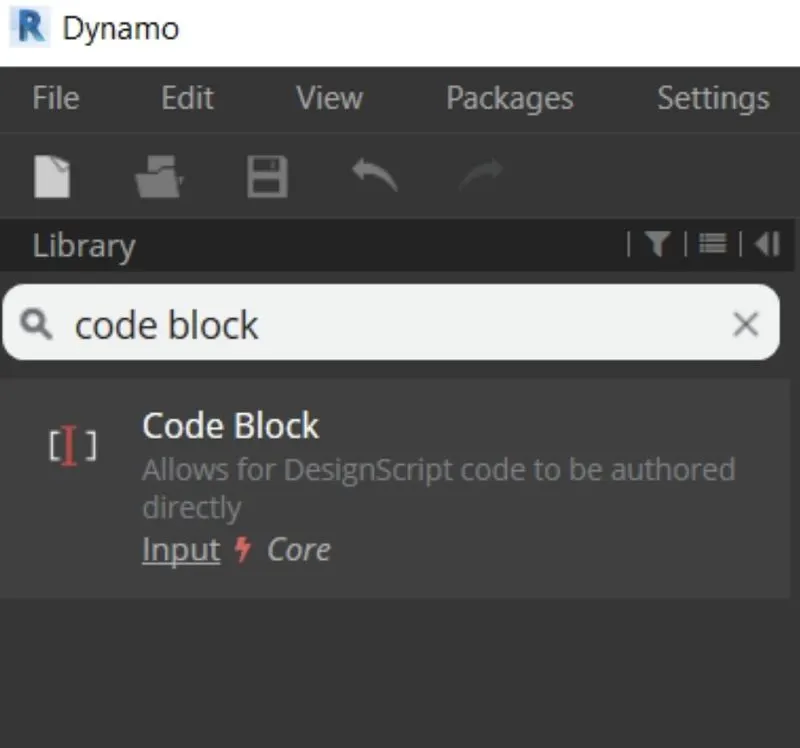
Now start the process by inserting three integer slider.This can be done by typing code block in the library search panel.
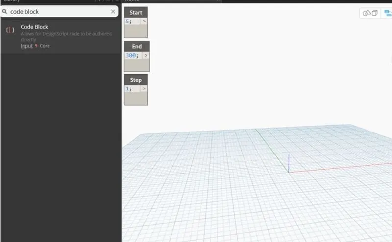
One block is named start (VALUE-5), Second block is named end(value-300), third one is called step (Value-1)
Now type range in the search panel of the library and insert it
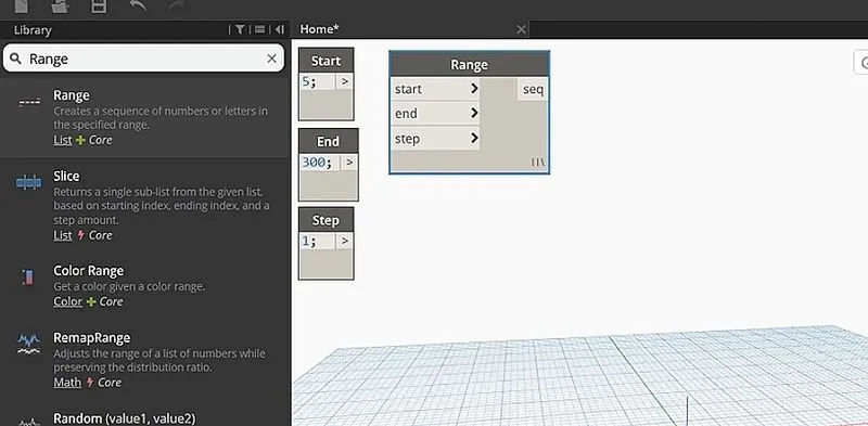
Now connect these three code block as input to the range block
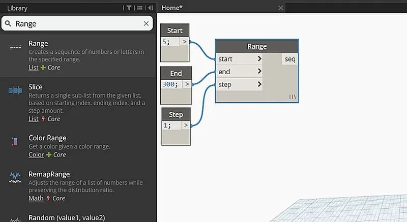
Now search points by coordinates in the searh panel
Connect the range block to the x coordinate of the point by coordinate block
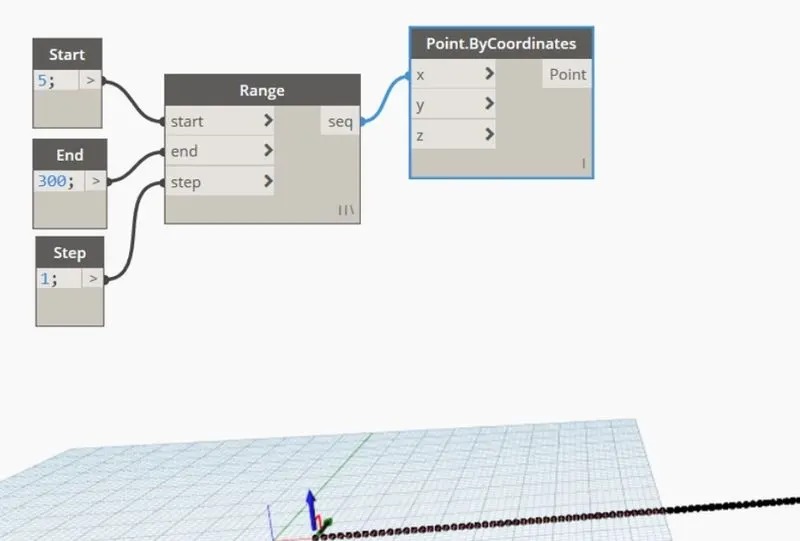
Now we have to produce sin wave out of these points for which we have to insert sin function which is given by math. sin option in the library
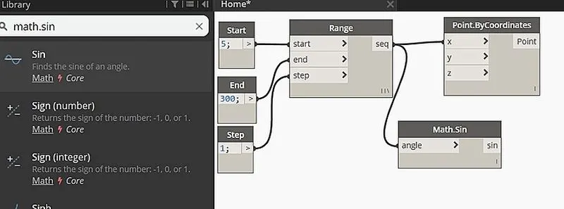
Sin values are very small so, we need to amplify it. For this, insert another integer slider and name it as amplifier
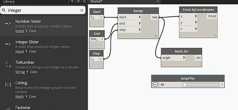
This amplifier code block needs to be multiplied to the sin block. For this , search product function in the library
Input for x value is sin block and for y value is amplifier
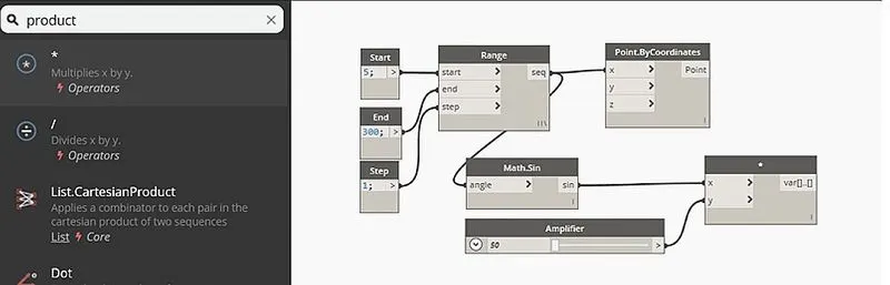
Next we have to provide phase for the sin curve so again insert slider and name it as phase
Now the phase block is then added to the amplified sin block
For this, insert add operator block from library
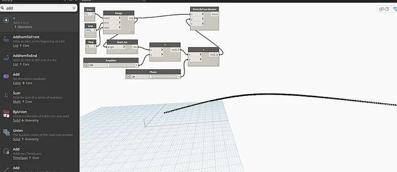
Now this is then connected to the y coordinate of the points by coordinates block
Hence the set of sinosidal points are obtained.Now we have to convert them to a curve
The curve can be created from nurbscurv.
Search nurbscurve in library and choose nurbs curve by control points
Now connect the points by coordinate block as input for the nurb curve . A line will be developed connecting the points
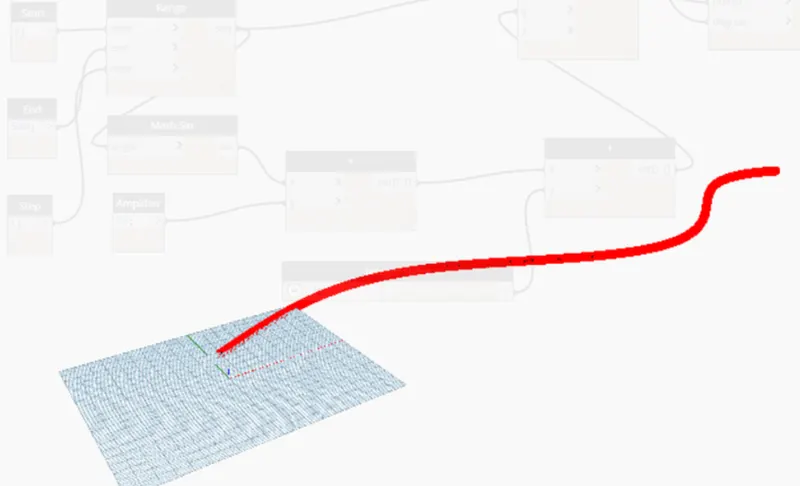
Hence sinusoidal curve is also developed. The next step is to develop surface .
For this first create a group of these items for easy manipulation. This can be done by selecting the required input blocks an then go to the edit option in the top portion and then choose create node from the selection . The entire thing will be grouped together
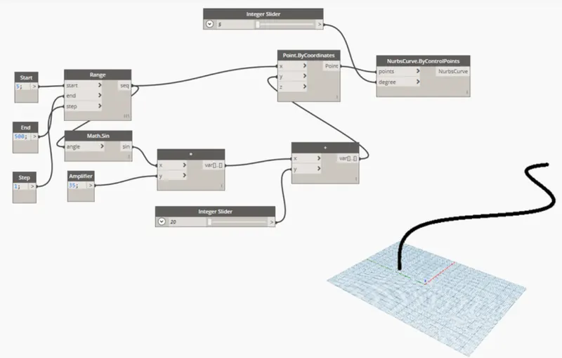
Now copy this entire blocks two times to create the surface . Adjust phase to view the two curves that are copied
Next step is to create the surface . For this , first create a list . This can be done by searching list.create in the searc panel of library
Then connect all the output of the sine curves as input for the list. This will serve as the input for surface by loft block
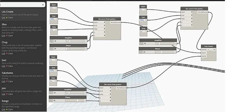
Now we have to create the surface . For this, search surface by loft
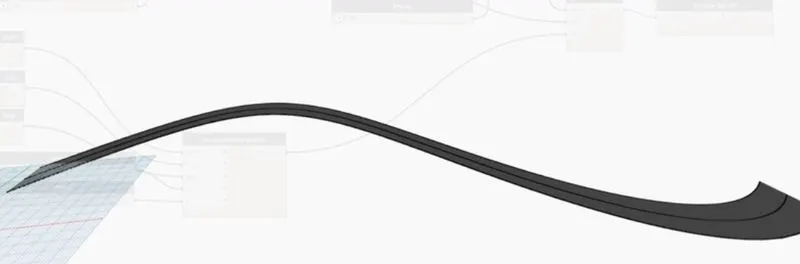
Hence the surface is developed out of the curve.
RESULT:
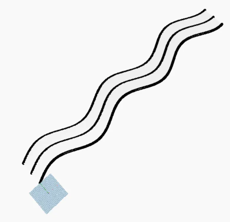
A set of sinusoidal points have been created as follows and sinosoidal curve connecting points is developed as given below
Surface is developed out of the curves as follows :
2) Create a conceptual layout of floor plan in dynamo . Using the tools available in dynamo link the lines to appropriate model elements in Revit by choosing the wall types and wall parameters. Make use of the sliders to slide through the height of the wall and length of the wall.
AIM:
To create a conceptual layout of floor plan in dynamo . Using the tools available in dynamo link the lines to appropriate model elements in Revit by choosing the wall types and wall parameters. Make use of the sliders to slide through the height of the wall and length of the wall.
INTRODUCTION:
Dynamo is an open source visual programming language for Revit, written by designers and construction professionals. It is a programming language that allows you to type lines of code; while also creating an algorithm that consists of nodes.
Establishing visual, systemic, and geometric relationships between the different parts of a drawing is key to the design process. Workflows influence these relationships from the concept stage to final design. Similarly, programming allows us to establish a workflow, but through formalizing algorithms. Using Dynamo, you can work with enhanced BIM capabilities in Revit. Dynamo and Revit together can be utilized to model and analyze complex geometries, automate repetitive processes, minimize human error, and export data to Excel files and other file-types not typically supported by Revit. Dynamo can make the design process more efficient, with an intuitive interface and many pre-made scripting libraries available as well.
The user interface for Dynamo is organized into five main areas, the largest being the workspace where programs are processed. The user interface sections include:
• Main menu
• Toolbar
• Library
• Workspace*
• Execution bar
The workspace is the place where designers develop visual programs, but it is also the place where any elaborate geometry is previewed. Whether you are working in a home workspace or in a custom node, you can navigate the workspace by using the mouse or buttons on the top right. However, we can change the navigation preview by switching from one mode to another in the lower right.
PROCEDURE:
Intially open the architectural template of REVIT software and go to the manage tab
In manage tab select the dynamo , then dynamo window opens and then go to the new option
In order to create the wall first we have to craete four control points
For this, search points by coordinates in the search panel of the library
1st one is named as origon (0,0,0) and the rest is named as control point 1(x,0,0), control point 2(0,y,0) and control point 3(x,y,0)
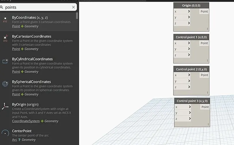
Now provide two integer sliders to provide the values for x and y
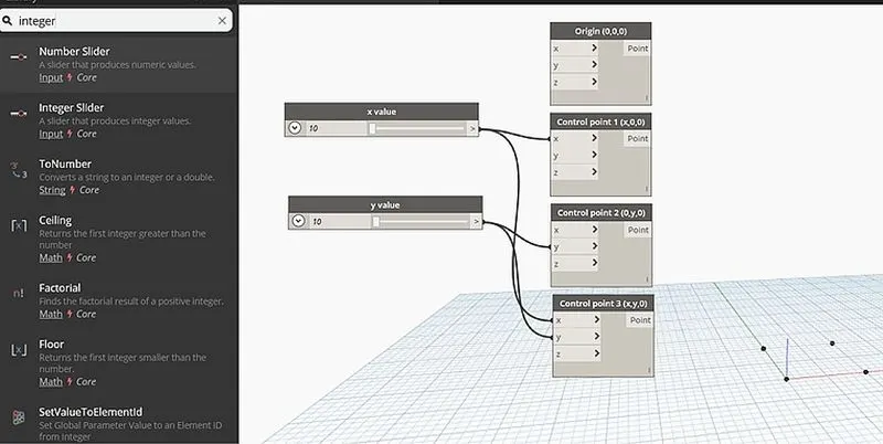
Now we have to connect these points by a line . So for this, search line by start and end point and insert 4 blocks.
The input for these blocks are the points created previously
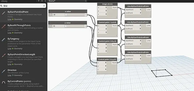
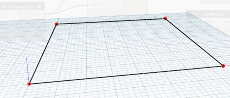
Hence the layout of the floor plan is obtained
Now search wall in the panel and choose wall by curve and height
So, for this input required are curve , height, level and wall type. Inputs are given as follows
For curve , combine all the four lines in a list by choosing list.create
For height, another number slider is chosen and name it as height
For level, search level in the search panel it will contain the levels available in the revit folder. Then choose the level in which we want to place the structure
For wall type, search the wall type in search panel and it will display the wall types linked in the revit file
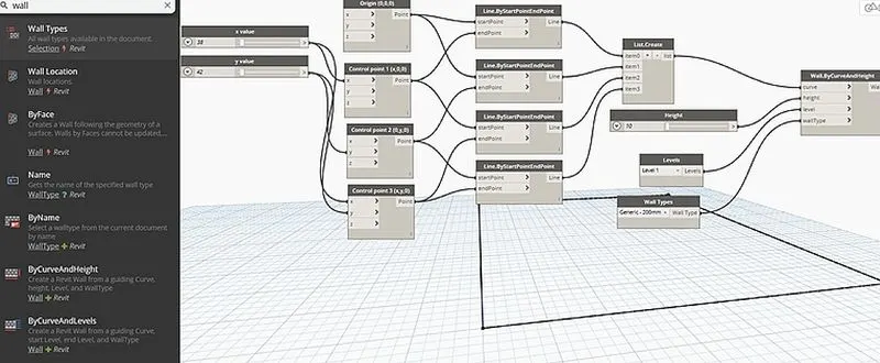
The floor plan layout is given below
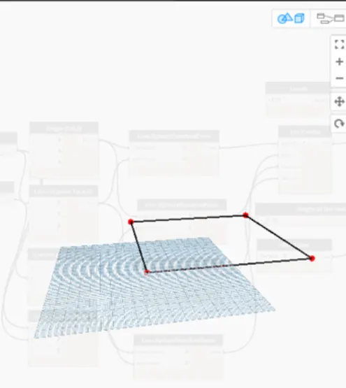
Now go to the revit file to view the 3d form where the height of the wall is visible
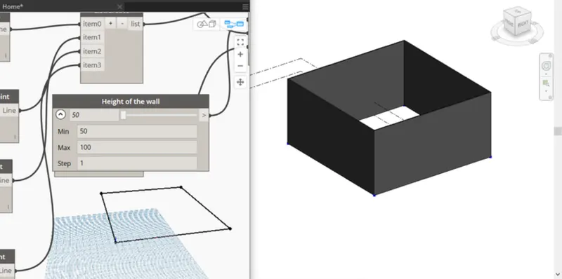
The height of the wall can be adjusted using the slider
Now we have to place the floor
For this, type floor in the library and select floor by outline curve , floor type and level
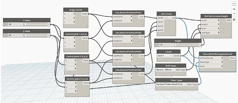
This can be viewed in 3D view in revit file
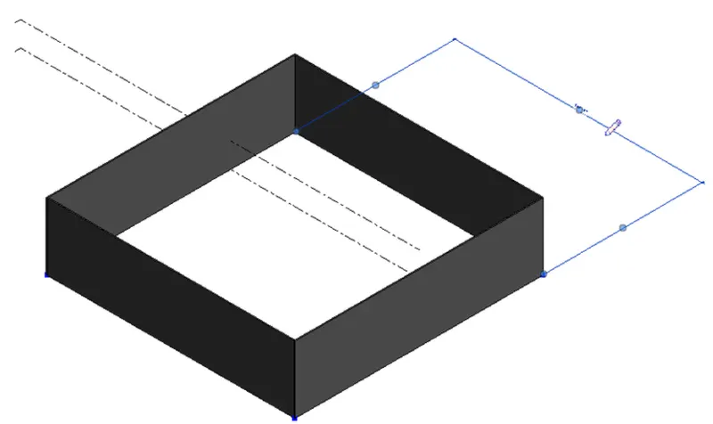
RESULT:
Hence the conceptual floor plan layout has been developed and is as follows
3) Create an array of model elements in Revit. Use dynamo to vary the properties of model elements by using the slider or code block
AIM:
To create an array of model elements in Revit. Use dynamo to vary the properties of model elements by using the slider or code block
INTRODUCTION:
Arrays are of two types:
-
Linear Array: This is where you take an element and repeat it (i.e. array it) along a straight path.
-
Radial Array: This is where you take an element and repeat it (i.e. array it) around a pivot point- i.e. in an arc.
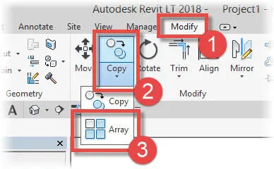
Select the “Modify” menu
(1) And then nested within the “Copy” drop-down menu
(2) We will find the “Array” tool
(3). Go ahead and click on this:
PROCEDURE:
Open a new architectural template in revit file.
In that go to architecture tab > colums > architectural colimns
Place the column
Now similarly 9 columns are created
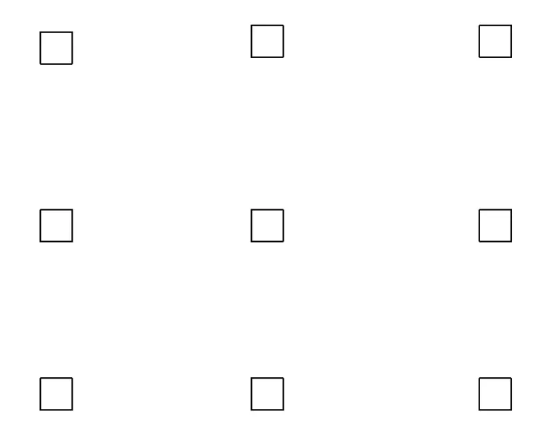
The properties of the model elements are varied using dynamo
Now open dynamo
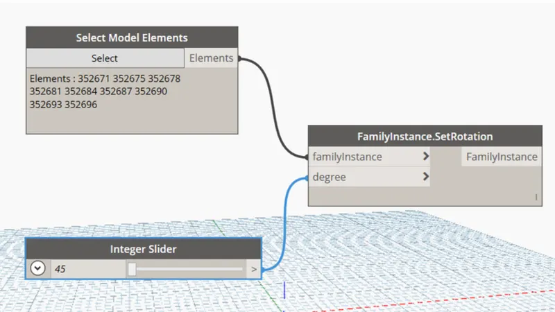
In search panel select model elements, integer slider and set rotation
The integer slider is renamed as rotation angle
Now select model elements block will be the input for family instances and integer slider(rotation angle) will be input for degree
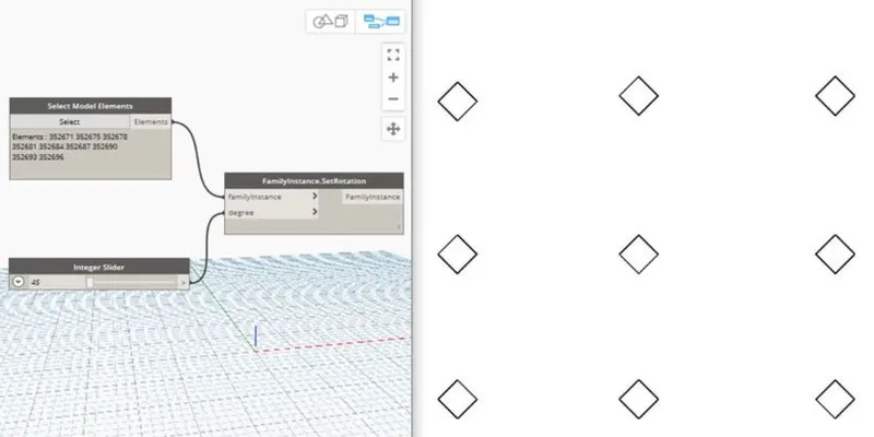
The rotation angle can be varied to desired value
RESULT:
The array of model elements have been created and their properties are being varied through the blocks created in dynamo
4) Create a conceptual mass in Revit and develop a parametric column by dividing the surfaces and apply the concepts similar to used in parametric walkway modelling. Use triangular bent or square shaped panels to add finish to the parametric column
AIM:
To create a conceptual mass in Revit and develop a parametric column by dividing the surfaces and apply the concepts similar to used in parametric walkway modelling. Use triangular bent or square shaped panels to add finish to the parametric column
INTRODUCTION:
The CDE provides flexibility early in the design process to express ideas and create parametric massing families that can be integrated into building information modeling (BIM). Use this environment to directly manipulate a design’s points, edges, and surfaces into buildable forms or parametric components.
You can design intelligent sub-components in the CDE that are nested in other models. For example, when the conceptual design is referenced into a larger building model, it can be used in multiple locations and regenerated. Similarly, design parametric components that have the intelligence to adapt to a divided surface.
The designs created in the CDE are massing families that can be used in the Revit project environment as the basis from which you create more detailed architecture by applying walls, roofs, floors, and curtain systems. You can also use the project environment to schedule floor areas, and to conduct preliminary spatial analysis.
Reference a design into a Revit project file and continue to modify it. For example, a design can be used to provide important reference information for the building model. Conceptual designs that have been saved as Revit project files can continue to be developed in the CDE.
Creating conceptual mass families means that the mass is external to the project. It uses the same tools to create the mass family, which is then saved and loaded into the project.
PROCEDURE:
Open revit software and under the families open a new > conceptual mass > mass
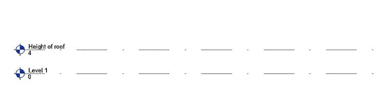
Now go to the elevation view and create a level at 3.6 m and name it as height of roof
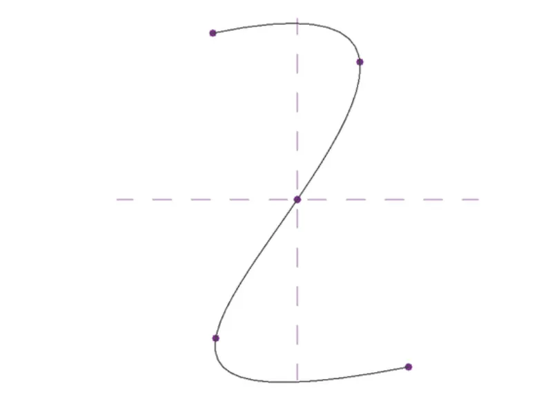
Now using spline tool draw the desired outline for the walkway
Now we have to create a rofile to sweep through the curve
For this we have to set the workplane at the points and develop a polygon at the workplane keeping the point as center
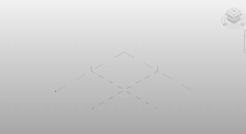
Now a polygon is developed with point as center
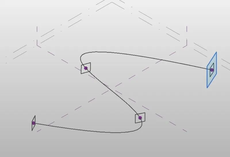
Similarly workplane and polygon is developed at all the nodes
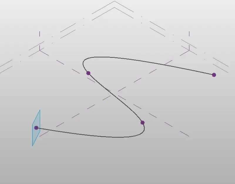
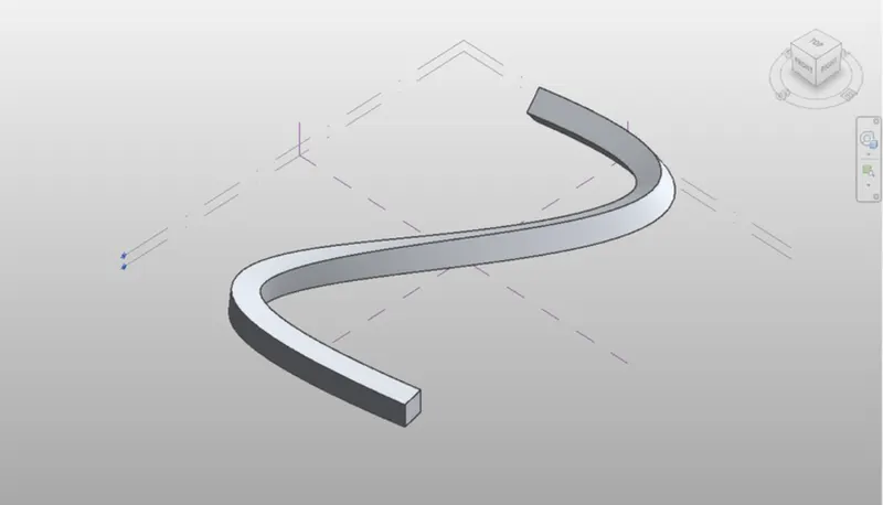
Now we have to create the surface which is done through sweep
For this, select all the polygons and the curve line and choose create from option
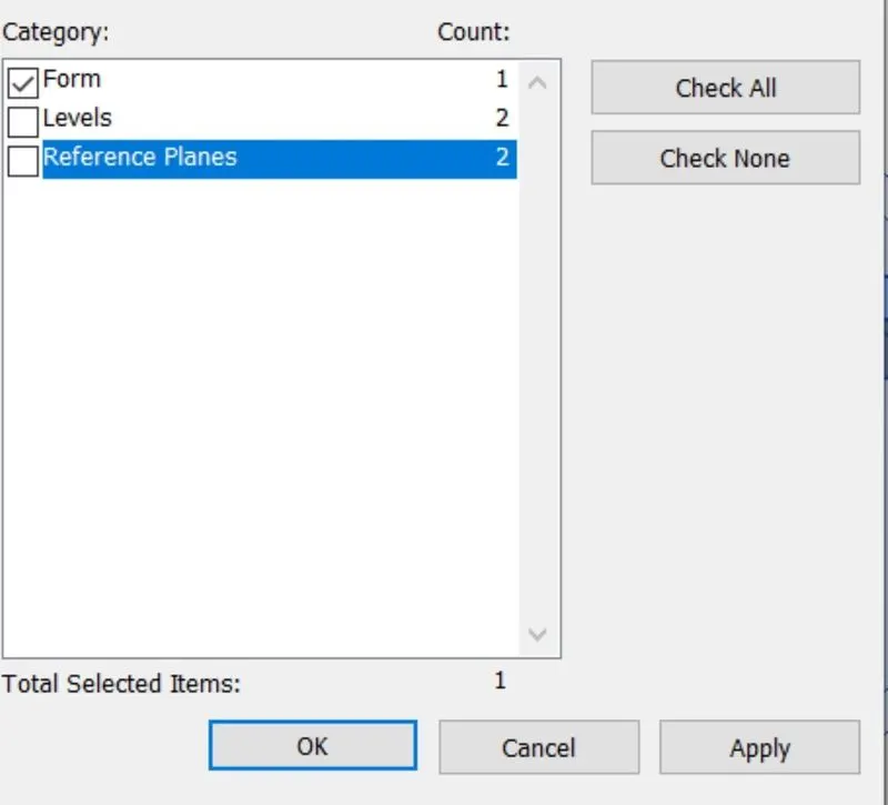
Now select the entire form and then filter and retain only the form
Now select the form > divide surface > then provide the pattern
Now open a new family > curtain panel pattern based
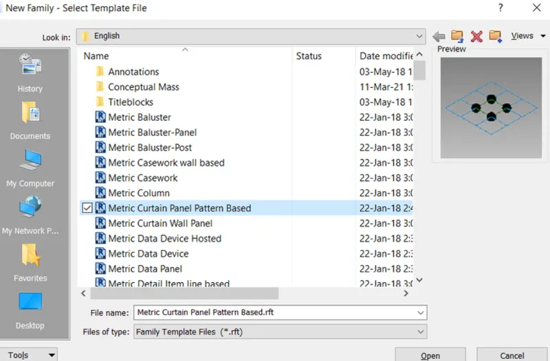
Now select the pattern as triangle bent
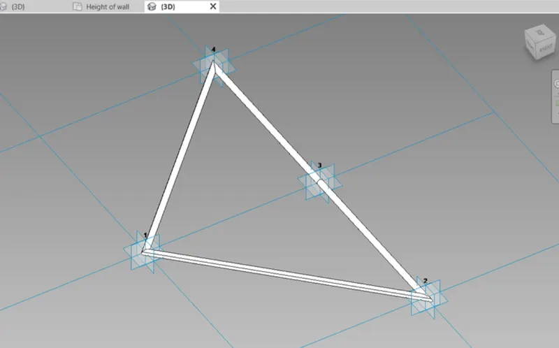
Then create a refrence point at center of the face . Then draw a circle of radius 3" at that refrence point
Now select the pattern refrence plane and circle created and choose create form
Now load this into the project . Now select the entire form of the walkway and filter it to retain only the divided surface
Then in the pattern select the family that we have created just now
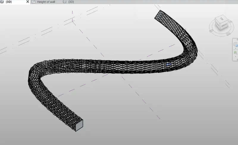
Hence the conceptual mass have been created
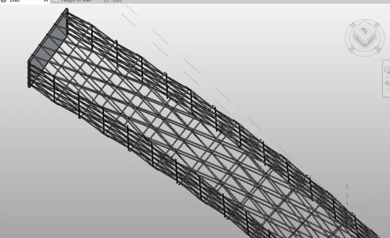
RESULT:
The conceptual mass have been created in REVIT and is given as follows
5) Use Dynamo to work on developing a Parametric Stadium. List your parameters and use the visual programming approach to complete the modelling, You can use the concepts discussed in parametric high rise tower in class for reference.
AIM:
To use Dynamo to work on developing a Parametric Stadium. List your parameters and use the visual programming approach to complete the modelling.
INTRODUCTION:
Parametric modeling refers to the relationships among all elements in a project that enable the coordination and change management that Revit provides. These relationships are created either automatically by the software or by you as you work.
In mathematics and mechanical CAD, the numbers or characteristics that define these kinds of relationships are called parameters; hence, the operation of the software is parametric. This capability delivers the fundamental coordination and productivity benefits of Revit: change anything at any time anywhere in the project, and Revit coordinates that change through the entire project.
Revit immediately determines what is affected by changes and reflects those changes to any affected elements.A fundamental characteristic of Revit is the ability to coordinate changes and maintain consistency at all times. You do not have to intervene to update drawings or other content. When you change something,Revit uses 2 key concepts that make it especially powerful and easy to use. The first is the capturing of relationships while the designer works. The second is its approach to propagating building changes. The result of these concepts is software that works like you do, without requiring entry of data that is unimportant to your design.
PROCEDURE:
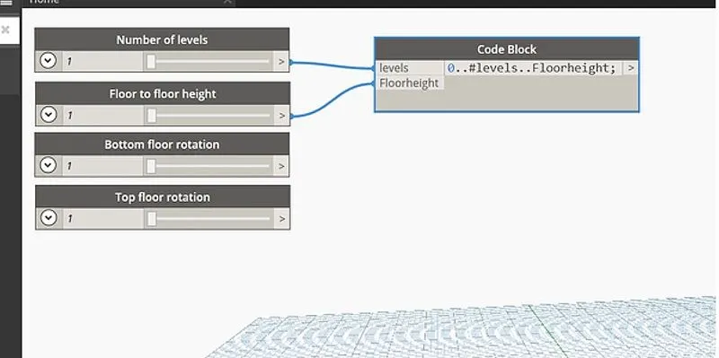
Intially open a new architectural template in revit and then open dynamo. Basic parameters to design a high rise structure is created as input in dynamo. Four integer sliders is taken from the library for the following
Number of levels
Floor to floor height
Bottom floor rotation
Top floor rotation
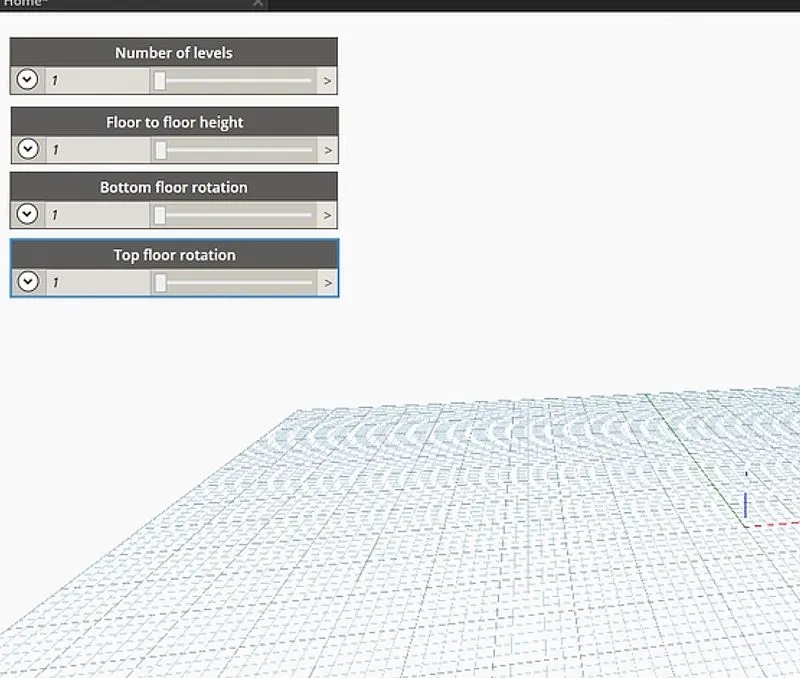
Now insert a code block from the library to combine level and floor to floor height and type 0..#levels..floorheight
Now connect the integer sliders named as levels and floor to floor height as input to the code block
Now search coordinates by origon in the library and insert it
Then connect the code block as input for z coordinate in the coordinate by origon block
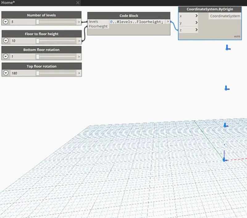
Five points are generated corresponding to 5 levels
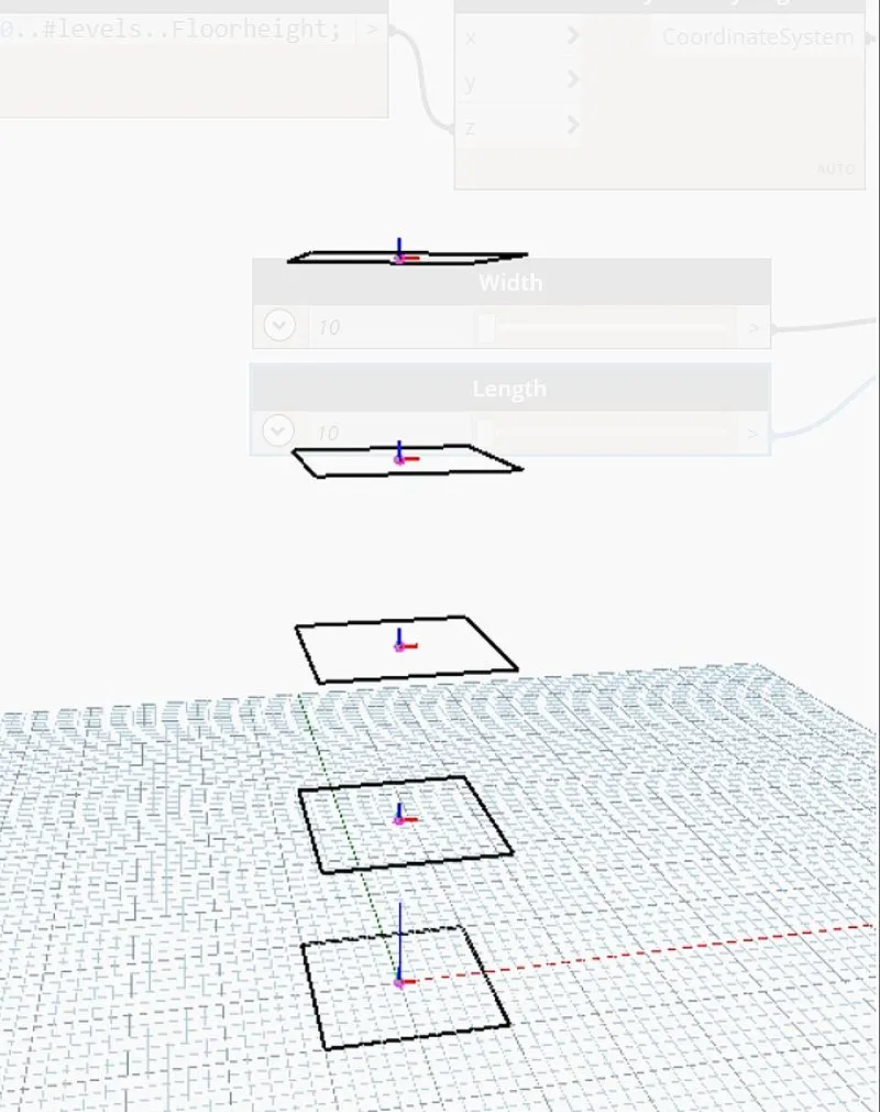
Now insert rectangle by width and length from the library
For this inputs required are coordinate system, length and width
So insert integer slider for length and width
Then connect the inputs for the rectangle block
Now we have to rotate the geometry . so, for this insert the rotate block from the library. The inputs required are
Geometry: Rectangle block
Origon : Insert an origon block from the library
Axis: Insert vector z axis from the library
Degrees: For this insert a code block and type bottom top...#level. The input for this code block is already available ie , bottom floor rotation, top floor rotation ad levels
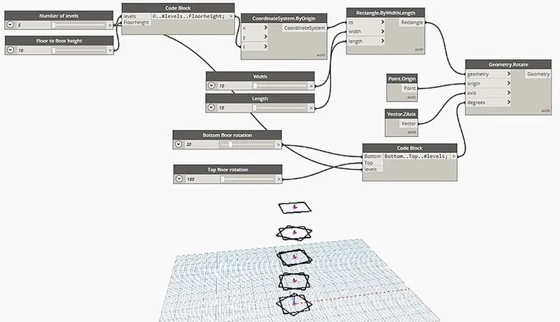
Now we have to create surface , for this type surface by loft in library
Then connect geometry , rotate block as input for surface by loft
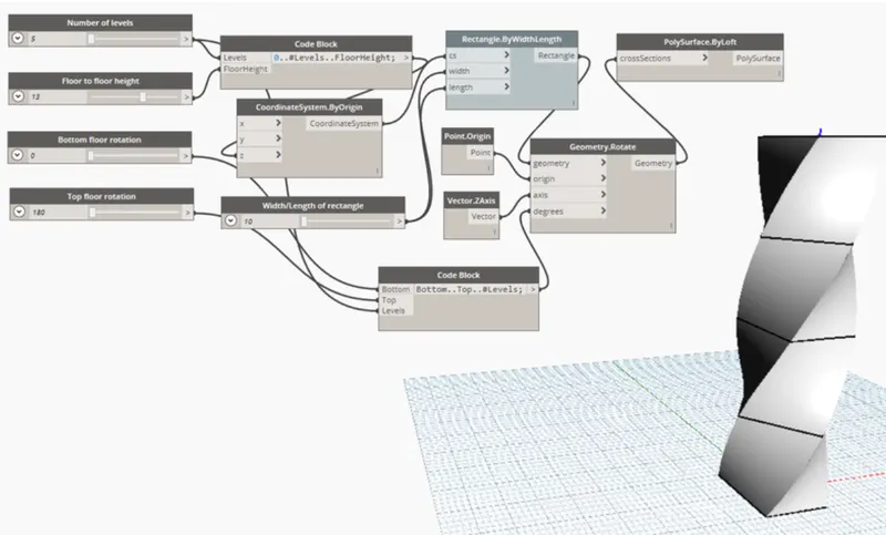
Hence the parametric stadium have been created
The number of levels and width and length of the rectangle can varied acordingly
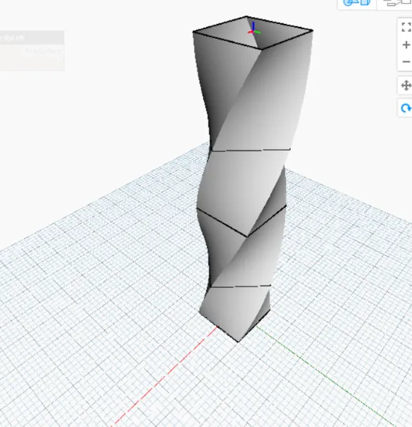
In the revit structure is visible as follows
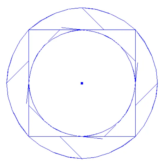
RESULT:
Developing a Parametric Stadium is done following the steps above