Creating Conceptual mass in REVIT and Creation of Sinusoidal curve and a Parametric stadium using Dynamo
1.
Aim
To Create points, Sinusoidal Curve and to create a surface by using the curve.
Procedure
- For using Dynamo go to Revit software and in manage tab there is an option called Dynamo. Click on it a new page will open with Dynamo.
- In search bar search for integer slider and select.
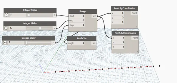
- Then range to connect the integer slider. Then search for points by co-ordinate. Click on it.
- Place these blocks in sequential order.
- Then connect the first integer to the start of range, and second to end of range and third to step.
- Provide integers value. Then from range to x of point by coordinate 1.
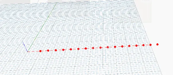
- Thus the points are created on the plane.
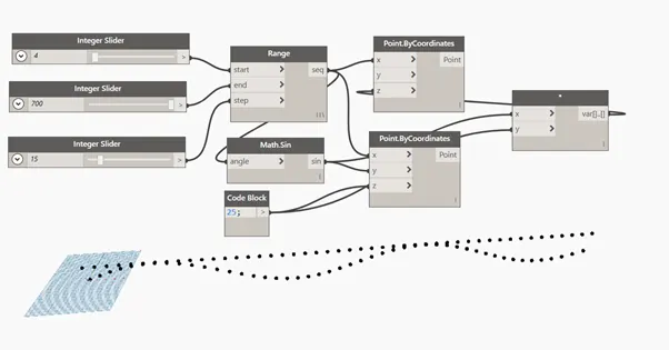
- Then for sinusoidal curve provide Math.sin, code block and Produce.
- Then connect Sequence of range to math. Sin.
- And enter the code block values as 25; then connect it to the Point by co-ordinate 2
- Then connect Math.Sine and Code block in x and y of product.
- Then the output of product is connected with the z of point by coordinate 1.
- Thus the Sinusoidal point curve has been created.
- For connecting the points create a block of Nurbs curve by control point
- We have 2 points by coordinates so create 2 Nurbs Curve and connect 2 points by coordinate with it.
- Then for creating the surface create list and connect the Nurbs to the list item 1 and 2.
- Then create surface and connect the output of list to the surface thus the surface has been created.
Out Put
Points
Sinusoidal Point Curve
Surface
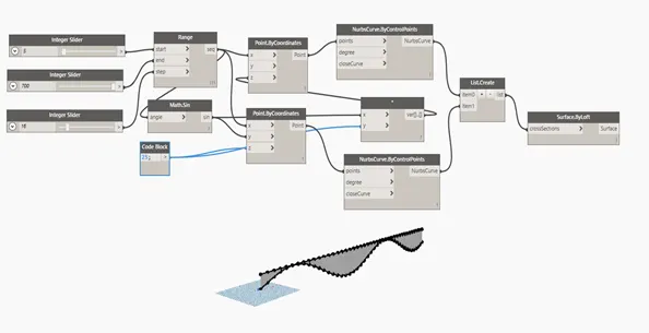
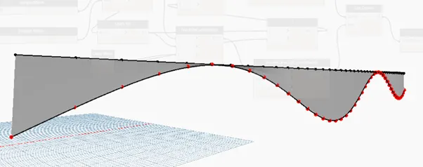
Result
Thus the points, Sinusoidal Curve and surface has been created by using Dynamo.
2.
Aim
To create a wall layout and floor by using Dynamo.
Procedure
- Go to Revit architect and in manage tab click Dynamo.
- A new window of dynamo has been opened.
- Then use Number Slider or integer and then points by coordinate to create points in the dynamo.
- Create4 points by coordinate block for four points.
- Connect number slider 1 and 2 in Points by coordinate x and y alternatively.
- Thus the points have created in the dynamo plane.
- Then for connecting all these points create a block called Line by start and end point.
- Create 4 line by start and end point to create 4 lines.
- Then connect points by coordinate output to line by start and end point.
- First connect the Point by coordinate Output to 1 Start and 2 Point by coordinate output to 1 end point.
- Then 2 output to 2 start point and 3 output to 2 end point.
- Then 3 output to 3 start point and 4 output to 3 end point.
- Then 4 output to 4 start point and 1 output to 4 end point.
- Thus the four lines have been created.
- The line by start and end output is connected with the list of items.
- For creating the wall and height of wall, create level, wall type and height of wall by number slider and wall by curve and height.
- Then provide level as Level 1, wall type as Generic 200mm and Height of wall as 4m then connect the outputs to wall by curve and radius.
- Thus the wall has been created.
- Then for creating floor create floor type and floor by outline type and level.
- Then select floor and connect it to floor type and connect level to level and list to outline curves.
- Thus the floor has been created.
Output
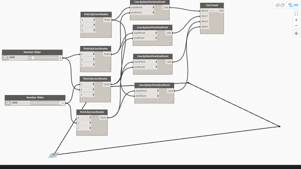
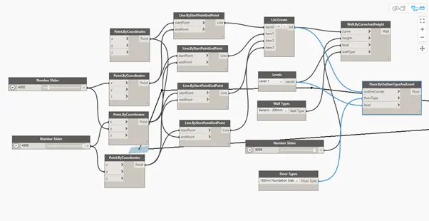
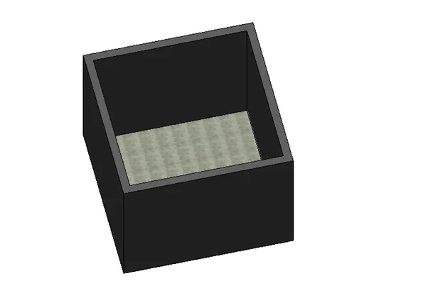
Result
Thus the wall and floor has been created by using dynamo.
3.
Aim
To create an array of model elements by using Revit and vary the properties of elements by using Dynamo.
Procedure
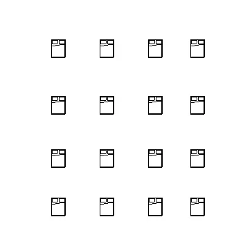
- Go to Revit software and create any element I have created sofa by using Array commend.
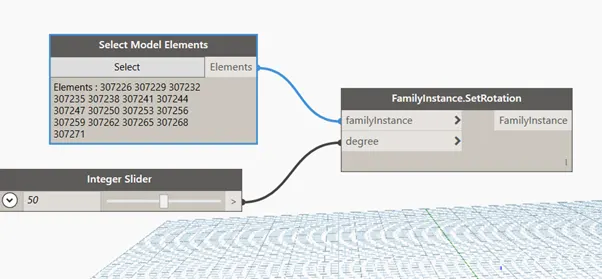
- Then open dynamo and use Select model element, rotate and integer slider blocks.
- To select model element, press select and go to Revit and select the created element.
- Then provide the angle of rotation to 30
- Then connect select model and integer slider to family instance and degree.
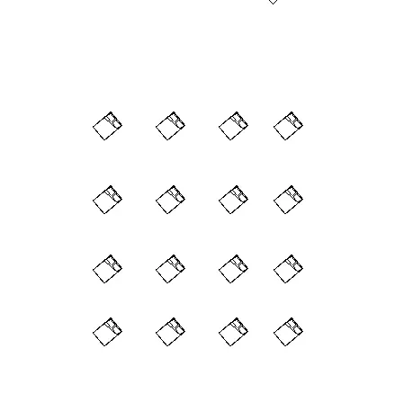
- Thus the elements are rotated to 30 deg.
- We can see the visual in Revit.
Output
Result
Thus the array of model has been created and the properties are varied by using Dynamo.
4.
Aim
To create a conceptual mass in Revit and develop a parametric column by dividing the surface and applying the concepts to be used in the parametric walkway modelling.
Procedure
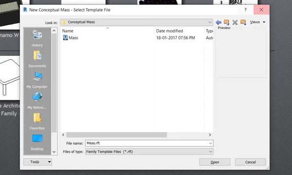
- Go to Revit software and open new and select conceptual mass and select imperial template then press ok.
- Then create level to a height of 20’
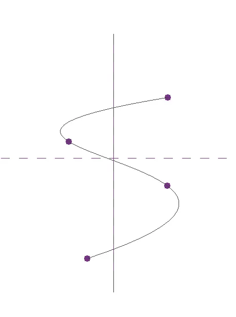
- Then go to floor plan in create tab select model line and choose spline option create a s shaped curve.
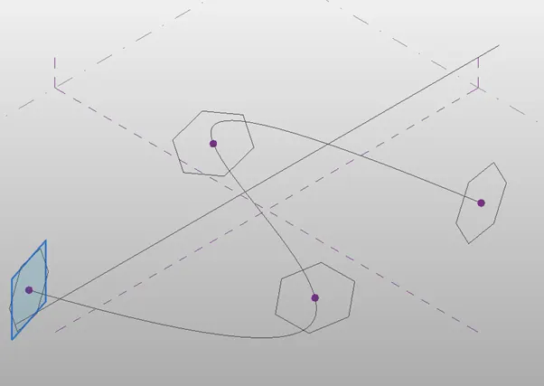
- Then need to place the plane select set option and choose the points and set the plane at each point.
- Then select polygon and place on each point on the plane with radius of 20’
- Once spline and polygon is created. Then make it solid by selecting the curve and start of the polygon.
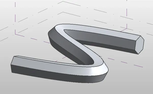
- Click on the create form option and select solid. A solid spline has been generated.
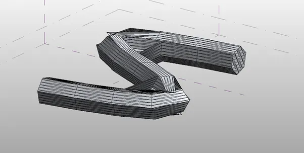
- Select the solid and choose divide surface.
- Then to apply the properties of triangular bent select the solid curve and in pattern there is an option called triangular bent click on it.
- Thus the triangular bent has been applied.
Output
Result
Thus the solid spline has been created and the property of triangular bent has been applied.
5.
Aim
To create a parametric stadium by using Dynamo
Procedure
- Go to Revit software and go to dynamo.
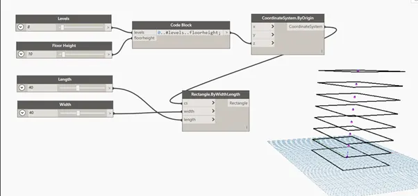
- Then for creating the parametric stadium we need levels, height of floor, length and width.
- Provide 4 integer slider a code block and point by origin.
- Rename the integer slider as Levels, Floor Height, Length and width.
- Then give levels as 8 and height of building as 10’ and length as 40’ and width as 40’
- Create a code in code block 0..levels..floorheight; then connect level and floor height to it.
- Then connect code block to coordinate system z axis. Also create point by origin and connect the code block to z axis we can see points.
- Then create rectangle with length, width and coordinate system.
- Then connect cs to cs and width to width and length to length. Thus rectangles have been created.
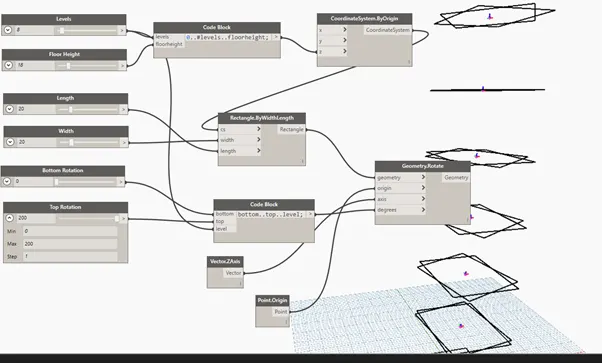
- Then create 2 integer slider for bottom and top floor rotation and code block for floor rotation.
- Create cod block as 0..bottom..top..levels; then connect bottom floor rotation to bottom and top to top and level to level.
- For creating rotation, create point by origin, vector Z axis and geometry.rotate.
- Then connect Rectangle to Geometry, Origin to Origin, Vector axis to Axis, and Rotation Code block to Degree.
- Thus the rotation has been seen in the plane.
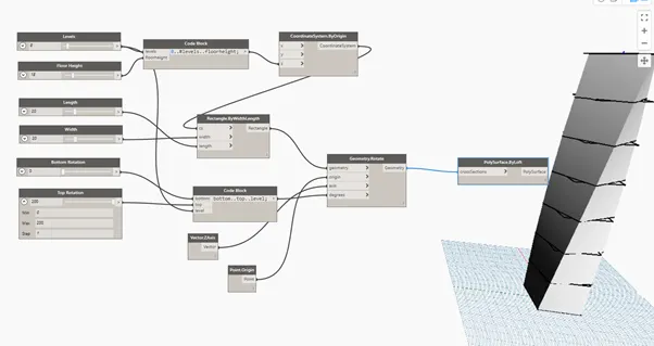
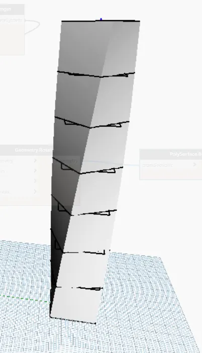
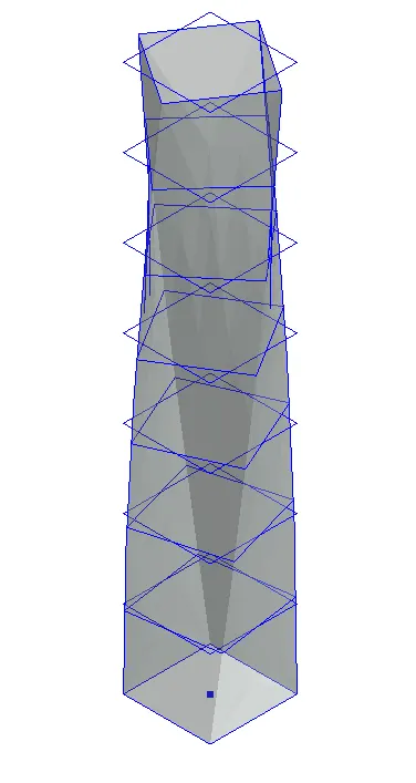
- At last to create surface, choose polysurface by loft and connect the geometry to the cross section of the loft.
- Thus the poly surface has been created.
Output
Result
Thus the parametric stadium has been created by using the code blocks in dynamo.