Creating Conceptual mass in REVIT and Creation of Sinusoidal curve and a Parametric stadium using Dynamo
1) Using Dynamo created a set of sinusoidal points, curve and a surface out of the curve :
AIM & INTRODUCTION :
AIM :
To create a set of sinusoidal points, curve and a surface out of the curve.
INTRODUCTION :
- Here, in dynamo we can create the 3D model structures using the tools available in it.
- The points and the coordinates along with sliders will be used to create the structure or curves.
- The elements created in the dynamo can be view and seen in the revit template after creation.
- In dynamo the element will be created as a line or curve then it can be converted as 3D model.
- As same as the revit template, we can also create models in a dynamo into 3 axizes.
PROCEDURE :
- To create a sinusoidal curve in dynamo.
- Open a new construction template in revit from New < Project < Construction template .
- Then open dynamo software from Manage < Dynamo.
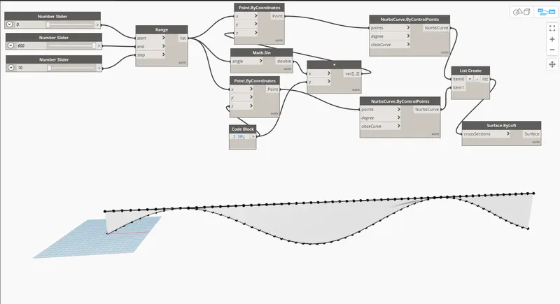
- Here, in dynamo open 3 integer sliders from the search < integer slider and click it 3 times to place it in the screen.
- Customise the integer values as start value, end value and step value.
- Then search Range and click it to place and connect the integer values to the similar names in the Range.
- Likewise, search point by coordinate along with (x,y,z) and click it 2 times to open 2.
- Followed by search and open Math.Sin , Code.Block and product (*).
- Then connect all those opened tabs appropriately as per the concepts discussed.
- Search and Open Nurbs curve.By control points and clicking it 2 times to open 2 tabs.
- Likewise search List Create and Surface.byLoft and connect all tabs appropriately.
- By connecting the Surface.byLoft with the list created, a surface will be created out of the curve.
RESULT :
2) Created a conceptual layout of floor plan in dynamo by using the tools available in dynamo and linked the lines to appropriate model elements in Revit by choosing the wall types and wall parameters. Used sliders to slide through the height of the wall and length of the wall :
AIM & INTRODUCTION :
AIM :
To create a conceptual layout of floor plan in dynamo by using the tools available in dynamo and link the lines to model elements in revit by choosing appropriate parameters.
INTRODUCTION :
- Here, in dynamo we can create the 3D model structures using the tools available in it.
- The points and the coordinates along with sliders will be used to create the structure or curves.
- The elements created in the dynamo can be view and seen in the revit template after creation.
- In dynamo the element will be created as a line or curve then it can be converted as 3D model.
- As same as the revit template, we can also create models in a dynamo into 3 axizes.
PROCEDURE :
- To create a sinusoidal curve in dynamo.
- Open a new construction template in revit from New < Project < Construction template .
- Then open dynamo software from Manage < Dynamo.
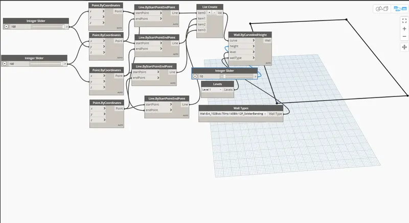
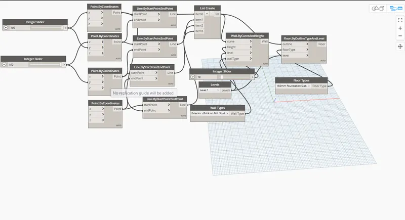
- Here, in dynamo open 2 integer sliders from the search < integer slider and click it 2 times to place it in the screen.
- Customise the integer values as appropriate to make a floor such as 100.
- Then search "point by coordinate" along with (x,y,z) and click it 3 times to open 3 tabs.
- And connect the 1st integer values to the "X" of first point by coordinate tab and "Y" of second Point by coordinate tab.
- Likewise, connect the 2nt integer values to the "X" of Second point by coordinate tab and "Y" of Third Point by coordinate tab.
- Followed by search and open "Line by start point end point" and click it 4 times to open 4 tabs.
- Then connect the Points created to the Start Point and End point of the Line by start and end point tabs appropriately.
- Likewise search List Create and add 4 lists in it and connect the 4 lines from the Line by start and end point appropriately.
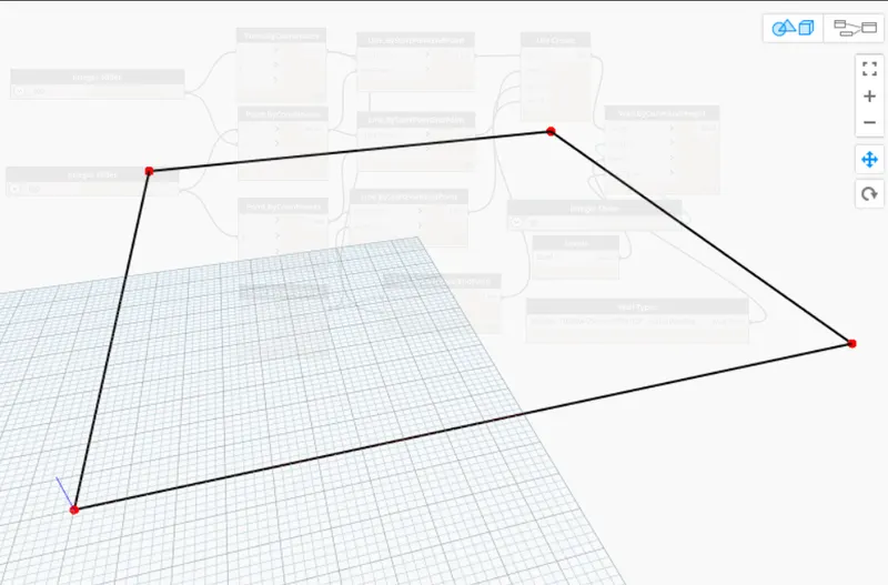
- It will create lines to all the points which was created by Point by coordinates.
- Search and Open Integer slider, Wall type, Level and clicking each 1 time to open each tabs separately.
- Then select the appropriate integer value (wall height) = 10, wall type and the Level = 1.
- Search and create "Wall by curve and height" and connect the customized values to it appropriately.
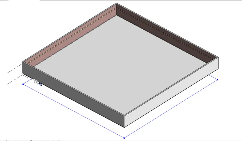
- By connecting all the appropriates to the "wall by curve and height" we can create the wall around the created floor line.
- Likewise the floor will be created by searching and opening the Floor type tab and Floor.by outline type and level tab.
- The conceptual floor layout will be created by connecting the floor type , Level and the wall to the "Floor.by outline type and level" as per the concepts discussed.
RESULT :
3) Created an array of model elements in Revit and Used dynamo to vary the properties of model elements by using the slider or code block :
AIM & INTRODUCTION :
AIM :
To create an array of model elements in revit and by using dynamo to vary the properties of model elements.
INTRODUCTION :
- Here, in dynamo we can create the 3D model structures using the tools available in it.
- The points and the coordinates along with sliders will be used to create the structure or curves.
- The elements created in the dynamo can be view and seen in the revit template after creation.
- In dynamo the element will be created as a line or curve then it can be converted as 3D model.
- As same as the revit template, we can also create models in a dynamo into 3 axizes.
PROCEDURE :
- To create a sinusoidal curve in dynamo.
- Open a new construction template in revit from New < Project < Construction template .
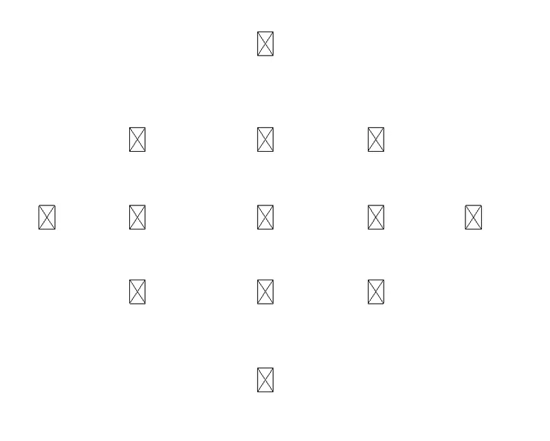
- Now create an array of Architectural Columns in the Revit template from Architecture < Column < Column architectural .
- Then open dynamo software from Manage < Dynamo.
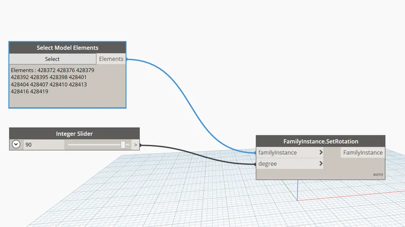
- Here, in dynamo open integer sliders from the search < integer slider and click it to place it in the screen.
- Customise the integer values as appropriate to make colums to rotate such as 90 degree.
- Search and open "Select model ements(Multipes)" and click select in it and Select all the columns created in the Revit template.
- Then search and open a "Familyinstance.SetRotation".
- Atlast connect Elements and integer slider to the opened Familyinstance to rotate the created colums as per the rotation value.
- We created an array of model elements in revit and by using dynamo to vary the properties of model elements by connecting the Elements and integer slider to the opened Familyinstance as per the concepts discussed.
RESULT :
4) Created a conceptual mass in Revit and developed a parametric column by dividing the surfaces and applied the concepts similar to used in parametric walkway modelling. Used triangular bent shaped panels to add finish to the parametric column:
AIM & INTRODUCTION :
AIM :
To create a conceptual mass in revit and to develop a parametric column by dividing the surfaces and adding a triangular bent shaped panel finish to the parametric column.
INTRODUCTION :
- In Revit we can create the 3D model structures in the project templates,
- Likewise in Revit we can also create a 3D model structures in Conceptual mass template.
- Here, in this conceptual mass workspace we can create a 3D element by creating a line and making it as a 3D element.
- To create a 3D element, the level lines and the Set work plane plays the major role.
- The 3D elements which can be created in all kinds of shapes in the Conceptual template such as spline, rectangular, circular etc.
PROCEDURE :
- To open a Conceptual mass work space first open a revit home.
- Then from File< New < Conceptual mass < Metric mass.
- Now click and open East Elevation view.
- Then try to create a level from the existing level upto the appropriate height.
- To pick the level upto the 12' , select the Pick line at the workspace tab under Create tab.
- And set the offset value as 12', select or pick the existing level to create a new level at the height of 12'.
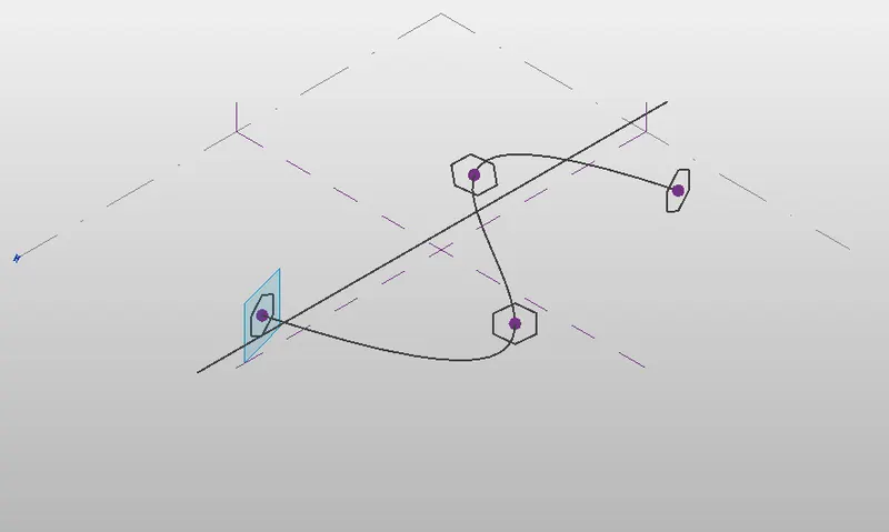
- Then again go to the 3D view and try to create a spline by placing points over the created level as spline.
- The spline option was selected from Create < Spline through points.
- After the creation of the spline line, the work plane has to be created at each points of the spline line.
- Evoke work plane from Create < Set (set work plane) and select each points.
- Then the Appropriate shape for the model which has to create will be selected the create tab.
- Here, the Inscribed Polygon was selected and which was created inside the Work plane created at the offset value of 12'.
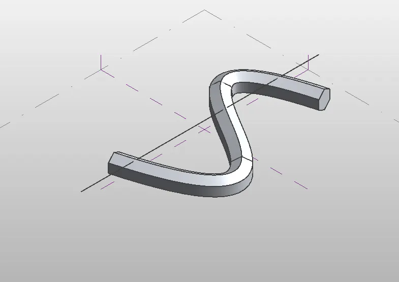
- Now select the Inscribed polygon at one corner of the spline and Select the option Create < Create form < Solid form displayed at the Work space.
- The 3D model will be created by connecting all the Inscribed polygon.
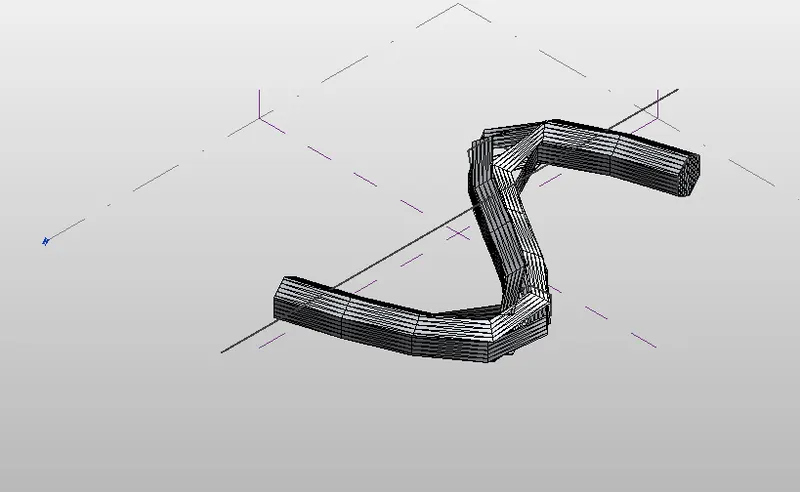
- Select the 3D model and click the option from Create < Divide path < Patterns (Properties Browser) < Triangular bent.
- Then we can see the Triangular bend shaped panel finish was applied on the Created 3D model.
RESULT :
5) Used Dynamo to work on developing a Parametric Stadium, Listed parameters and used the visual programming approach to complete the modelling, by using the concepts discussed in parametric high rise tower in class for reference :
AIM & INTRODUCTION :
AIM :
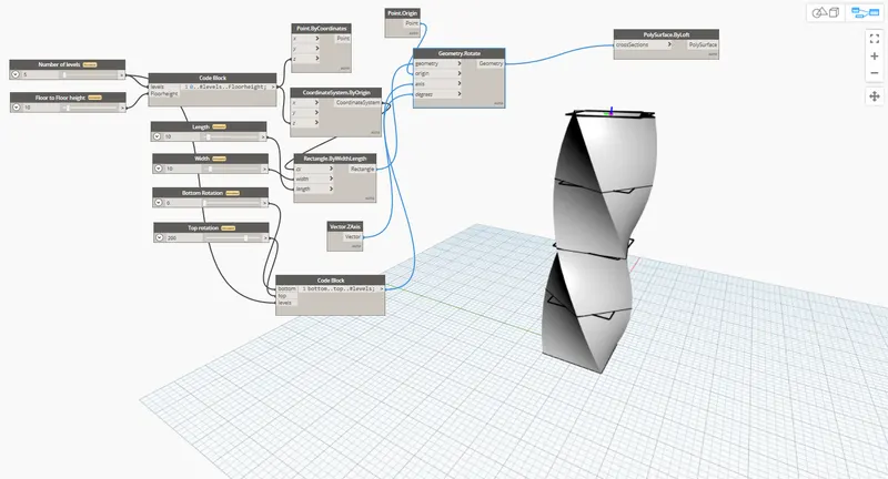
To create a Parametric high rise tower model by using Dynamo.
INTRODUCTION :
- Here, in dynamo we can create the 3D model structures using the tools available in it.
- The points and the coordinates along with sliders will be used to create the structure or curves.
- The elements created in the dynamo can be view and seen in the revit template after creation.
- In dynamo the element will be created as a line or curve then it can be converted as 3D model.
- As same as the revit template, we can also create models in a dynamo into 3 axizes.
PROCEDURE :
- To create a Parametric high rise tower model by using Dynamo.
- Open a new construction template in revit from New < Project < Construction template .
- Then open dynamo software from Manage < Dynamo.
- Here, in dynamo open 2 integer sliders from the search < integer slider and click it 2 times to place it in the screen.
- Change the Slider name as appropriate such as 1st slider as "No. of levels" and 2nd slider as "Floor to Floor height".
- And customize the No.of levels = 5 and Floor to Floor height = 10.
- Likewise, Search and open the "Code Block", there type and create Levels and Floor Height box in it.
- Then connect the 1st and 2nd Slider to the Levels and Floor height appropriately.
- Followed by search and open tabs such as "Point by Coordinates (x,y,z)" , "CoordinateSystem.byorigin" (xyz).
- And connect the Code Block (Levels, Floor height) to the X,Y,Z 's appropriately.
- Search and create 4 Integer sliders and edit the names as "Length", "Width", "Bottom Rotation" , "Top Rotation".
- Likewise Search and Create these tabs such as "Rectangle.by widthLength" , "Vector Z axis" , "Code Block (Bottom, top and levels)".
- Then connect the Created integer values to the created "Rectangle.by widthLength" , "Code Block (Bottom, top and levels)".
- And Search and Create tabs such as Point Origin, GeometryRotate (Geometry, origin, axis, degree).
- Connect all the created tabs appropriately to make the High rise tower model with the rotation.
- To make a 3D surface to the created model, Search and open a tab named Polysurface.byloft (Cross section).
- Then connect the Geometry to the Cross Section to Visualize the 3D surface of the twisted High rise Tower model.
RESULT :