Creating Conceptual mass in REVIT and Creation of Sinusoidal curve and a Parametric stadium using Dynamo
1) Using Dynamo create a set of sinusoidal points and create a curve and create a surface out of the curve.
Ans.1.
Aim :- Using Dynamo create a set of sinusoidal points and create a curve and create a surface out of the curve.
Introduction :- Using Dynamo create a set of sinusoidal points and create a curve and create a surface out of the curve.
Procedure :-
- Open REVIT
- Go to manage tab and select Dynamo.
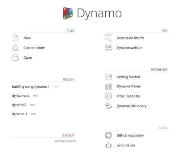
- We will get interface as shown below.
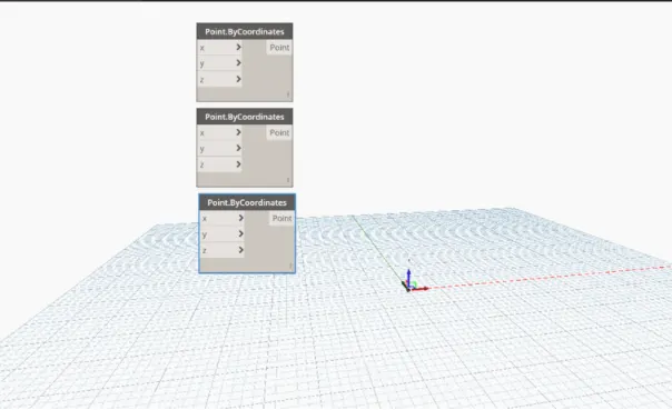
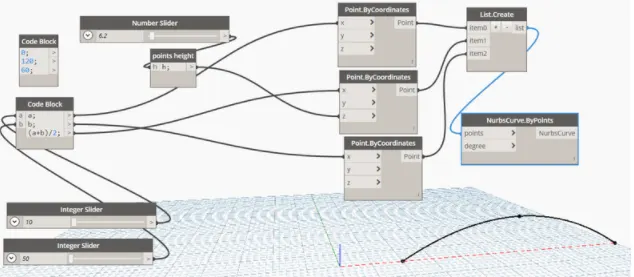
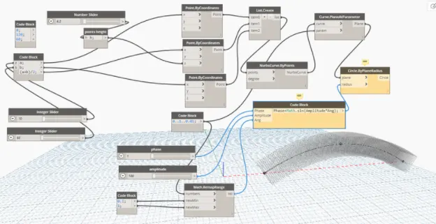
- After opening Dynamo, search point in search option and bring them on screen.
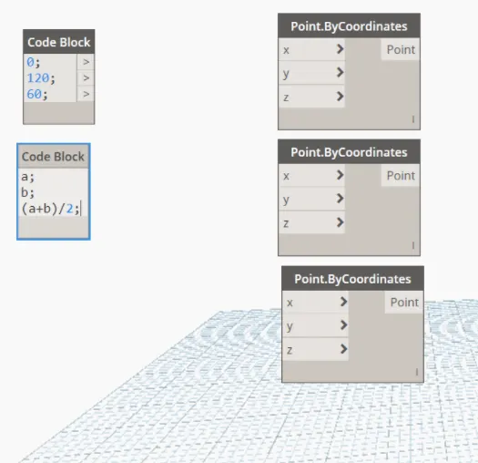
- Then search code block and bring them on screen and enter values.
- Now search sliders in search option and bring them on screen, set values as 0 to 50 and 50 to 100.
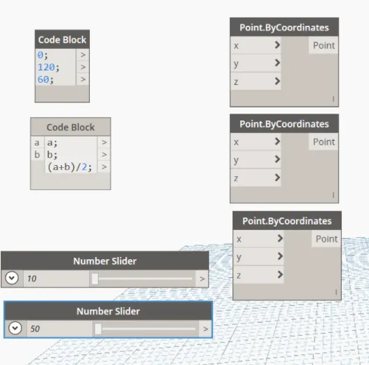
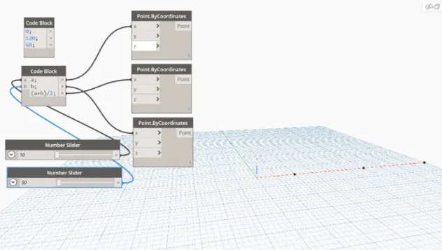
- Give the input of both the sliders to the variable a and b in the code block, and the output of which are connected to x of all the three points of coordinate.
- Introduce code block and name it as points height and give variable as h, take another number slider, connects its output to input of heights and the output of height is connected to z coordinate of middle point by coordinate.
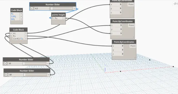
- If we make an increase in number of slider we can see the inclined point system in a form of curve as shown below.
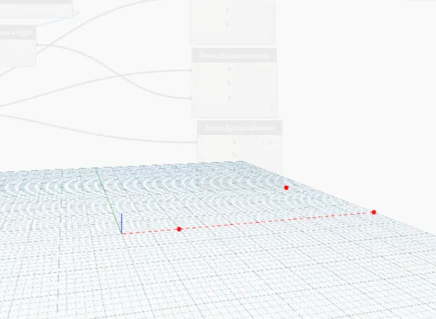
- To make it curve introduce nurbs by point and list to interface, connect the output of points by coordinate to each input of list n craete
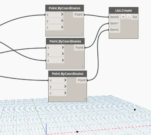
- Output of list is connected to input of nurbscurve, we will gwt a curve as shown below.
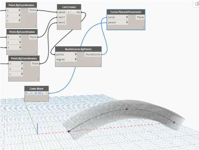
- Now, introduce plane at parameter into the interface and connect the output of nurbs to the input of curve (plane at parameters)
- In orderr to give the second input of (plane at parameter) take another code block and eneter its values
- We get a surface as shown below.
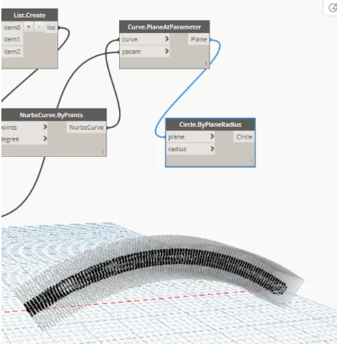
- Now introduce circle into screen, connect the output of plane parameter to the input of circle.
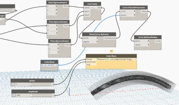
- In order to give radius create a code block and name it as phase+math.sin(amplitude*ang) ;
- Give input to the amplitude and angle using code block.
- Connect its output to the radius of circle.
Result :-
The results are shown above.
2) Create a conceptual layout of floor plan in dynamo . Using the tools available in dynamo link the lines to appropriate model elements in Revit by choosing the wall types and wall parameters. Make use of the sliders to slide through the height of the wall and length of the wall.
Ans.2.
Aim :- Create a conceptual layout of floor plan in dynamo . Using the tools available in dynamo link the lines to appropriate model elements in Revit by choosing the wall types and wall parameters. Make use of the sliders to slide through the height of the wall and length of the wall.
Introduction :- Create a conceptual layout of floor plan in dynamo . Using the tools available in dynamo link the lines to appropriate model elements in Revit by choosing the wall types and wall parameters. Make use of the sliders to slide through the height of the wall and length of the wall.
Procedure :-
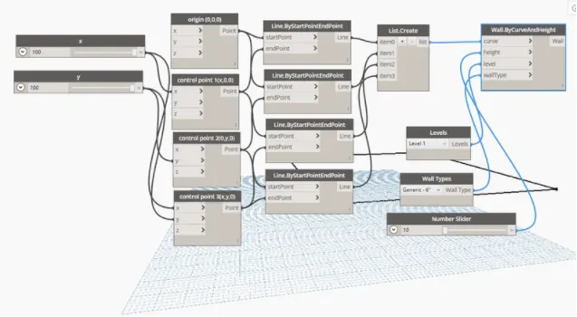
- Open Dynamo, search point in search option and bring them on screen.
- Give different name to each point as shown below.
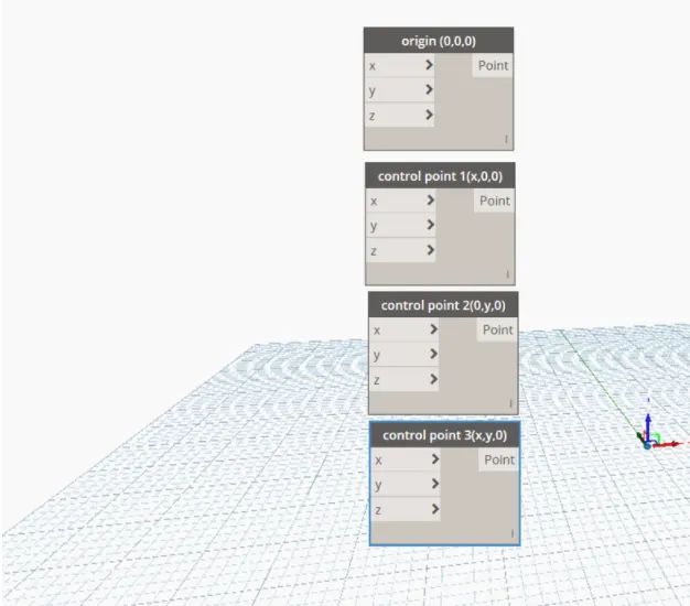
- Now bring number slider on the screen and name them as x and y, and set their limits as 10 to 100.
- connect the output of x and y to control point 1 followed by 2 and 3 as shown in figure
- Now introduce line by start point to end oint on the screen
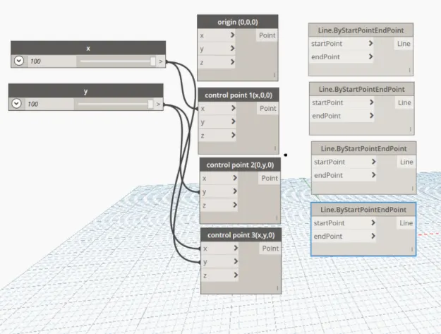
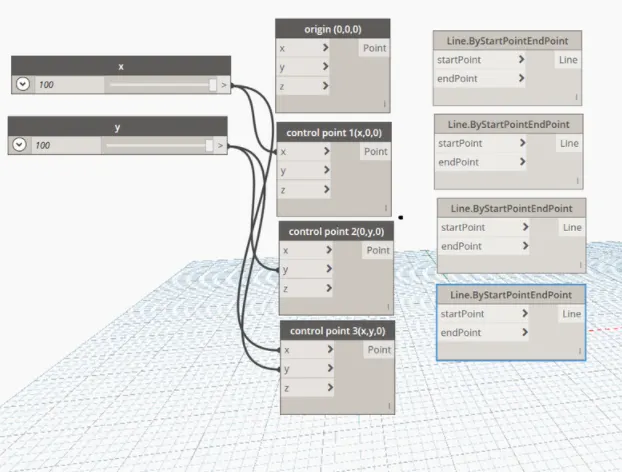
- Connect the output of points to the input of lines by start point and end point i.e. origin to start point and end point to control point 1. In this way connect all the points forming a layout as shown in the figure.
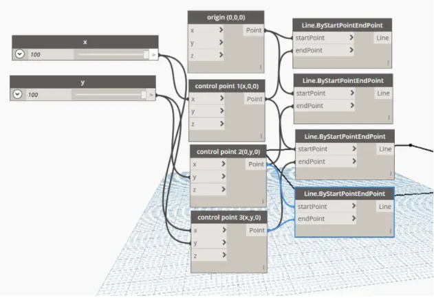
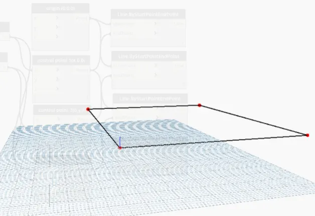
- Now, introduce wall by curve into the screen and its required inputs such as levelss, heights, wall type and curve.
- Set the wall type as generic 5" , followed by height as 10 to 40 using number slider.
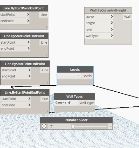
- Now, introduce the list option and connect the output of lines to the input of list, then connect its output to the curve.
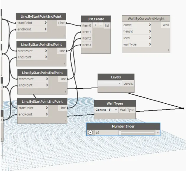
- Go back to the Revit screen, change the view to 3d, now we can alter the height of the layout using the height option (number slider) , can increase or decrease it.
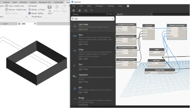
Result :-
The results are shown above.
3) Create an array of model elements in Revit. Use dynamo to vary the properties of model elements by using the slider or code block
Ans.3.
Aim :- Create an array of model elements in Revit. Use dynamo to vary the properties of model elements by using the slider or code block.
Introduction :- Create an array of model elements in Revit. Use dynamo to vary the properties of model elements by using the slider or code block.
Procedure :-
- Open Revit and draw a rectangular column, copy the same and place it beside the previous column.
- Now copy the group of two columns and place them above the previous group forming a group of 4 columns.
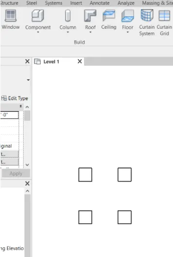
- Now go to manage tab and open dynamo.
- Search select model elements, set rotation and bring them on the screen.
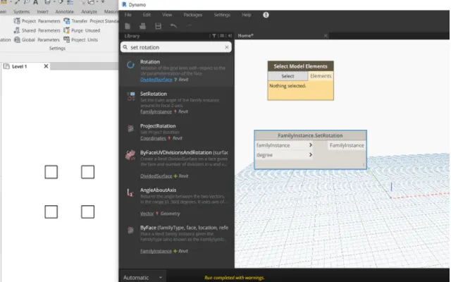
- Now click the select option and select all the four columns,you get a value.
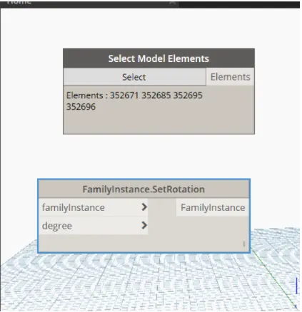
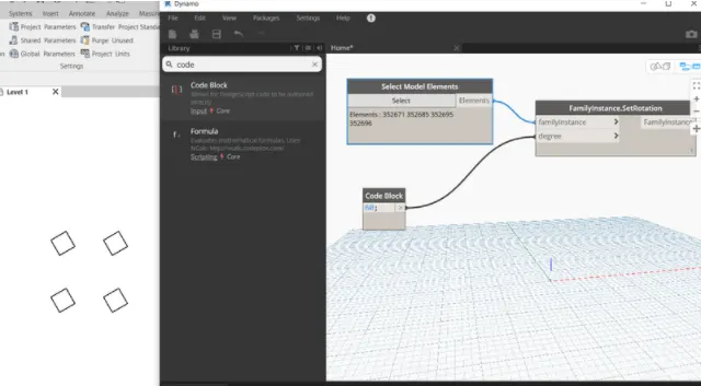
- Now insert code block and enter the angle, connect its output to the degree.
- We can see all the four columns have been rotated at an angle of 60.
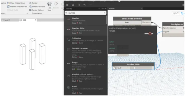
- Now insert number slider and connect it to the degree.
- As we increase the cursor in number slider we can see the changes in Revit screen in 3D
Result :-
The results are shown above.
4) Create a conceptual mass in Revit and develop a parametric column by dividing the surfaces and apply the concepts similar to used in parametric walkway modelling. Use triangular bent or square shaped panels to add finish to the parametric column.
Ans.4.
Aim :- Create a conceptual mass in Revit and develop a parametric column by dividing the surfaces and apply the concepts similar to used in parametric walkway modelling. Use triangular bent or square shaped panels to add finish to the parametric column.
Introduction :- Create a conceptual mass in Revit and develop a parametric column by dividing the surfaces and apply the concepts similar to used in parametric walkway modelling. Use triangular bent or square shaped panels to add finish to the parametric column.
Procedure :-
- Open Revit and go to file option and select families.
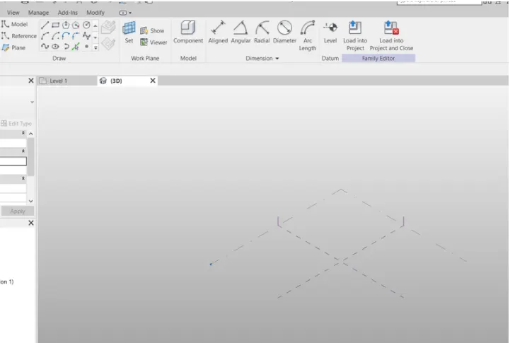
- Open conceptual mass from the family.
- We get an interface as shown below.
- Change the view to North view and increase level to 10'.
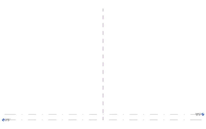
- Go to floor plan view, we can interface as shown below
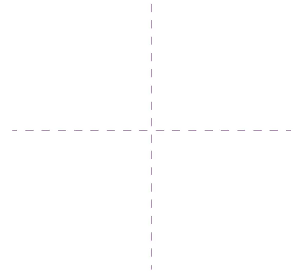
- Select the spline option and draw as shown below.
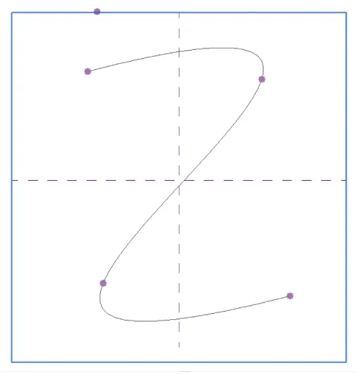
- Change the view to 3D
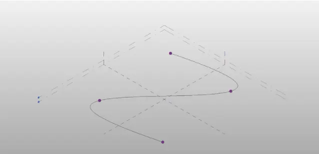
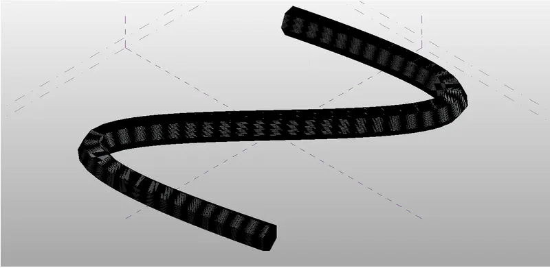
- Select the entire figure and click create form, resulting model we will get like this.
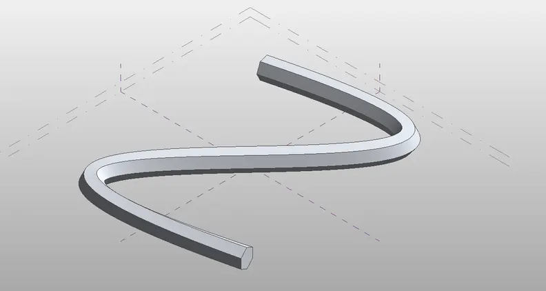
- Now from properties bar change the boundary to square or trianglular
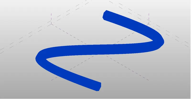
- Now go to file option, select families and select curtain wall pattern based.
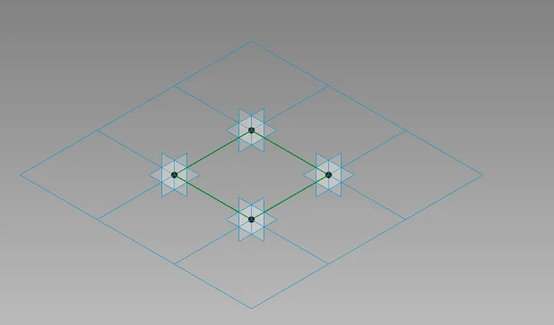
- In order to create circle select the center point of any one side and draw circle at that point.
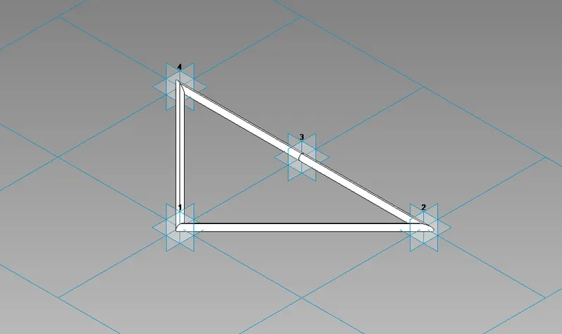
Result :-
The results are shown above.
5) Use Dynamo to work on developing a Parametric Stadium. List your parameters and use the visual programming approach to complete the modelling, You can use the concepts discussed in parametric high rise tower in class for reference.
Ans.5.
Aim :- Use Dynamo to work on developing a Parametric Stadium. List your parameters and use the visual programming approach to complete the modelling, You can use the concepts discussed in parametric high rise tower in class for reference.
Introduction :- Use Dynamo to work on developing a Parametric Stadium. List your parameters and use the visual programming approach to complete the modelling, You can use the concepts discussed in parametric high rise tower in class for reference.
Procedure :-
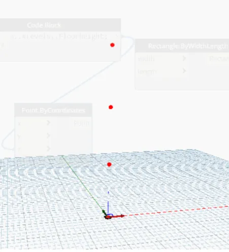
- Open Revit and go to Dynamo and make 4 integer slider and change their name as shown below
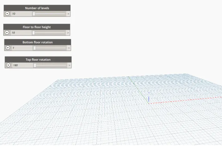
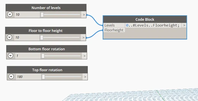
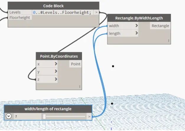
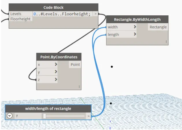
- Insert code block and insert the command as shown 0. #levels....floor height;
- Connect the output of levels to input level of code block
- Connect the output of floor height to the input of floor height (code block).
- Now introduce the rectangle by width using code block and give inputs to it using codeblock i.e. width/length of rectangle.
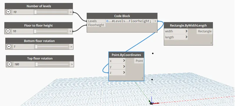
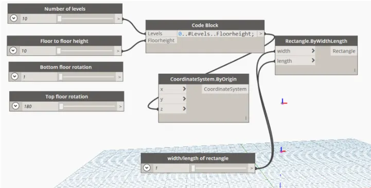
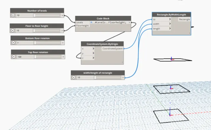
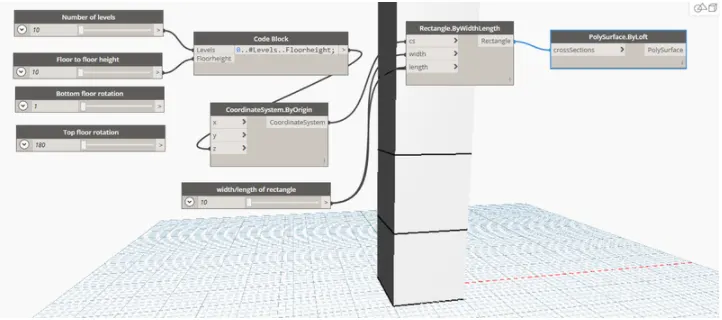
- Introduce the polysurface by loft and connect output of rectangle to its input
- Introduce geometry rotate and give inputs to it i.e. geometry, origin, axis, degree, as shown below.
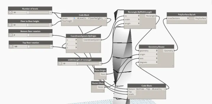
- Now we can rotate the figure by using of top floor rotation and bottom floor rotation.
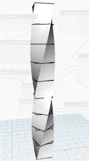
Result :-
The results are shown above.