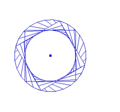
Creating Conceptual mass in REVIT and Creation of Sinusoidal curve and a Parametric stadium using Dynamo
1) Using Dynamo create a set of sinusoidal points and create a curve and create a surface out of the curve.
Aim :To create a set of sinusoidal points, create a curve and create a surface out of the curve using dynamo.
Introduction :
- Dynamo is extra add-ins in the Revit software which uses the visual programming.
- We can find dynamo in the manage tab of the Revit software in visual programming panel.
- In dynamo nodes are inserted and wired by following the logical sequence to create the geometry.
Procedure :
Step 1
- Open Revit software and open the new imperial architectural template file.
Step 2
- Go to the manage tab and open the dynamo tool from visual programming panel of manage tab.
Step 3
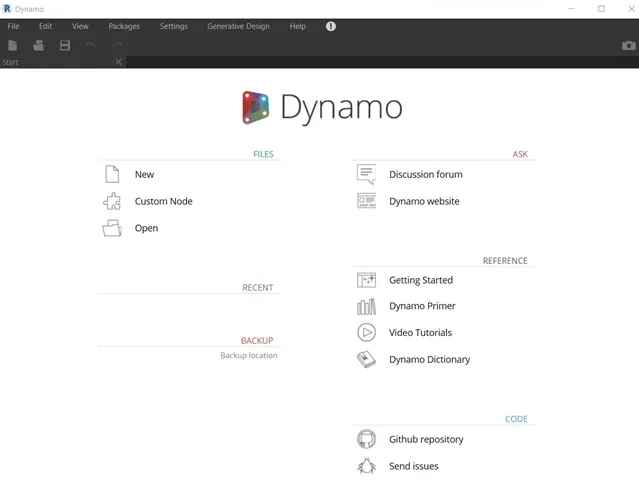
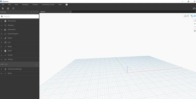
- Select new option to open the new dynamo file from the window as shown below.
Step 4
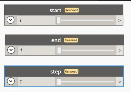
- Type the integer slider in the library browser to add the integer sliders as shown below.
Step 5
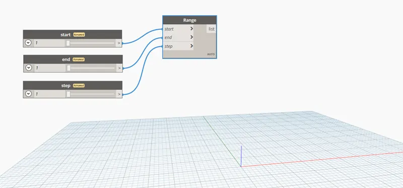
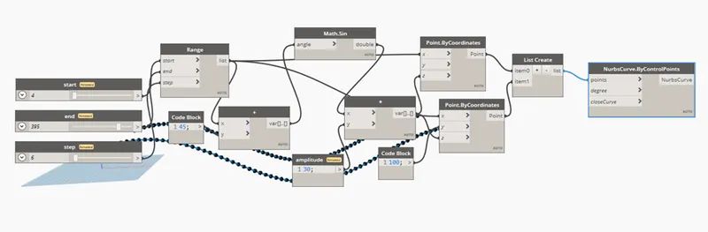
- Type range in the library browser and add range node and connect the start, end and step points by wire to the integer slider as shown below.
Step 6
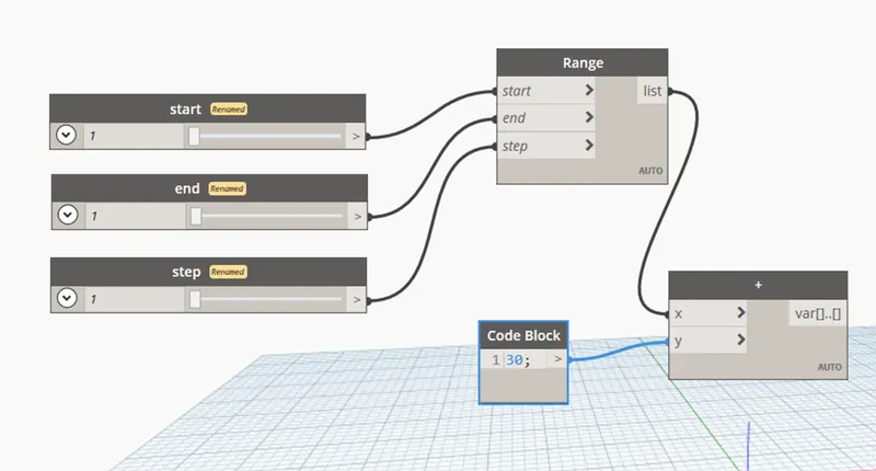
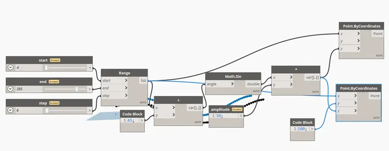
- Type add in the library to get add node and add code block by double clicking on the screen and type the value 30 to add phase angle and make wire connection as shown below.
Step 7
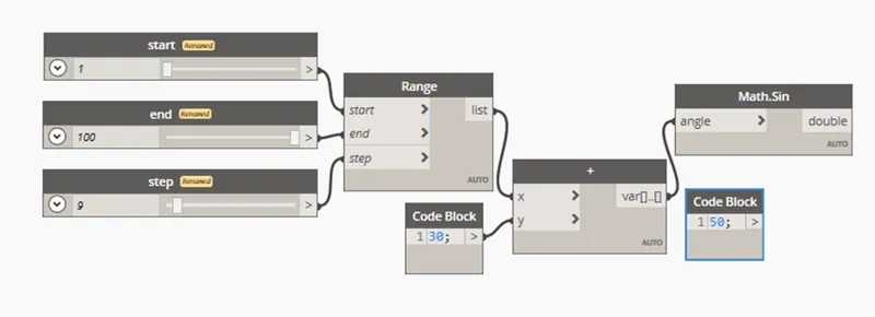
- Add math sine node by typing sine in the library browser and code block by double clicking on the screen as shown below.
Step 8
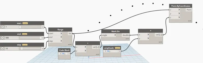
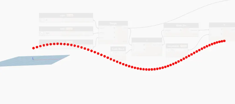
- Type point by coordinate from library to add and make wire connection, the resultant curve in the dynamo is shown below.
Step 9
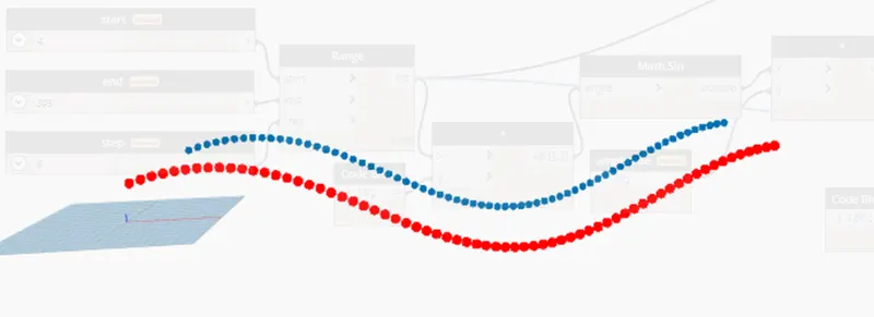
- To add similar curve add point node by coordinates and make connections as shown below.
Step 10
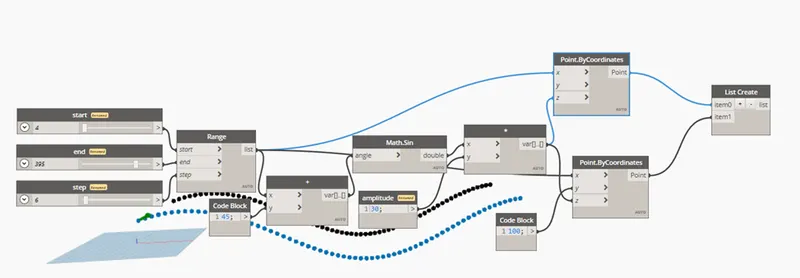
- Add the list node by typing list in the library browser and make connections as shown below.
Step 11
- Add Nurbscurve by control points and connect it to the created list as shown below.
Step 12
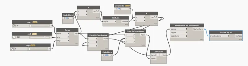
- Add surface by loft to create surface using library and make the connections as shown below.
Result :
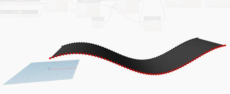
Therefore, the curve is created in the dynamo using visual programming as shown below.
The resultant curve surface in the dynamo is shown below.
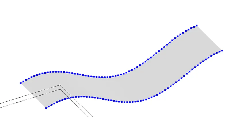
The resultant curve surface in Revit is shown below.
2) Create a conceptual layout of floor plan in dynamo . Using the tools available in dynamo link the lines to appropriate model elements in Revit by choosing the wall types and wall parameters. Make use of the sliders to slide through the height of the wall and length of the wall.
Aim : To create a conceptual layout of floor plan in dynamo and use the tools available in dynamo and link the lines to model elements in Revit by choosing wall types and wall parameters.
Introduction :
- Dynamo is visual scripting program with the help of which we can generate the geometry.
- In dynamo we can generate code without having to know how to code.
- In dynamo we can generate points followed by curves followed by surfaces by using visual programming in which we insert the nodes of appropriate parameters and wire them in proper logical sequential order.
Procedure
Step 1
- Open the Revit software, go to manage tab and open the dynamo by clicking on it.
Step 2
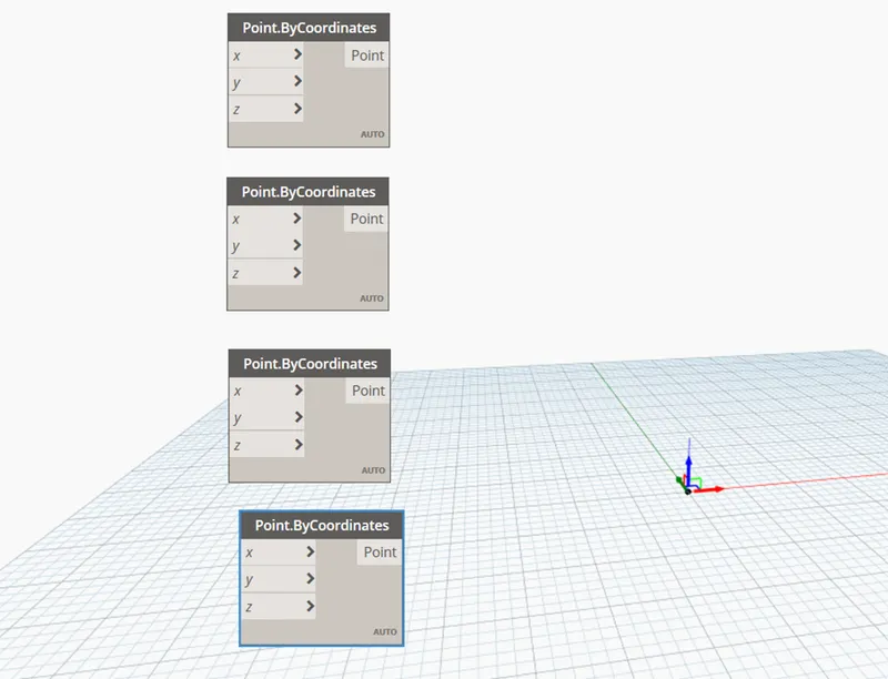
- Type point in library browser and insert four point nodes by coordinate as shown below.
Step 3
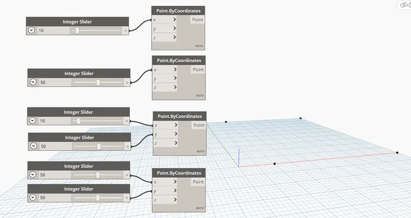
- Type integer slider in library browser and insert appropriate number of integer slider nodes and set the appropriate values in the integer sliders as shown below.
Step 4
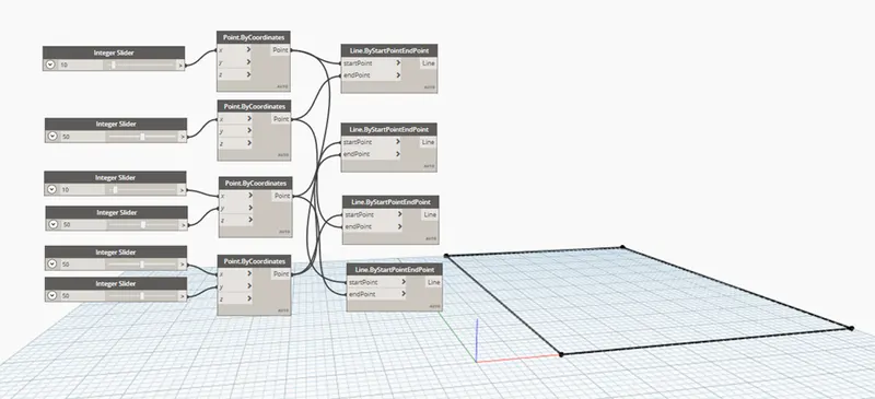
- Type line and choose line by ByStartPointEndPoint and make appropriate wire connections to draw the lines connecting point nodes as shown below.
Step 5
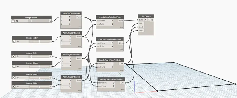
- Type list in library browser and add list node and connect the points nodes to the list node as shown below.
Step 6
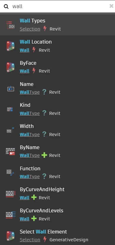
- Type walls in library browser and choose wall ByCurvesAndHeights from library browser.
Step 7
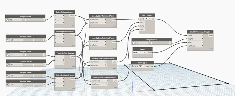
- Type levels and add level node and choose appropriate level from the nodes.
- Type integer slider in library browser and add integer slider node an set the required height to the walls in integer slider.
- Similarly add wall type node using library browser and select appropriate wall type by clicking on the drop down of the wall type node as shown below.
Step 8
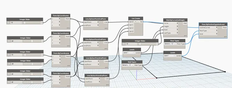
- Type floor and choose ByOutlineTypeAndLevel from library browser and also add the floor type node and integer slider nodes using the library browser as shown below.
- Set the appropriate value in integer slider and connect it to the degree of outline type and level node.
- Similarly select the type of floor in the floor type node and connect it to floor type in the floor outline node as shown below.
Result
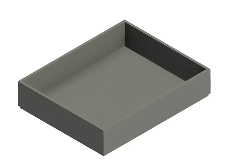
Therefore, conceptual layout of floor plan using the tools available in dynamo is created in Revitas shown below.
3) Create an array of model elements in Revit. Use dynamo to vary the properties of model elements by using the slider or code block
Aim : To create an array of model elements in Revit and vary the properties of the model elements using dynamo.
Introduction :
- Dynamo is the visual programming tool which is used to create the geometries by inserting the nodes and wiring them into proper sequence.
- By creating the model elements in the Revit followed by linking the elements in the dynamo we can change the shape or properties of element in Revit by operating on sliders of dynamo.
Procedure :
Step 1
- Open the Revit software and select architectural template.
Step 2
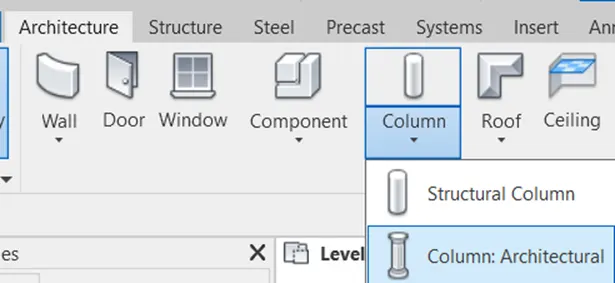
- Select the column architectural from architectural tab and insert the columns at the appropriate position as shown below.

Step 3
- Go to manage tab and select dynamo from visual programming panel and open the new file in the dynamo.
Step 4
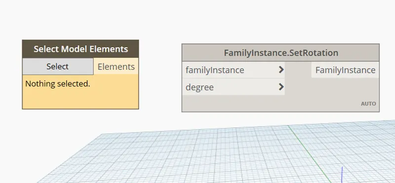
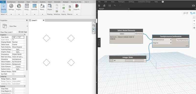
- Type select model element in the library browser
Step 5
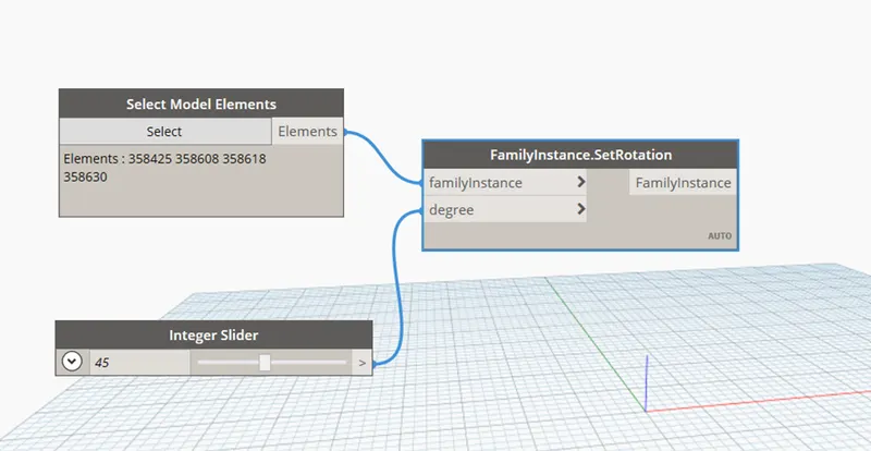
- Type integer slider in library browser and connect it to the rotation node by setting appropriate rotation angle as shown below.
- Select the select option from select model element node and select the columns from Revit software by dragging using the mouse.
Step 6
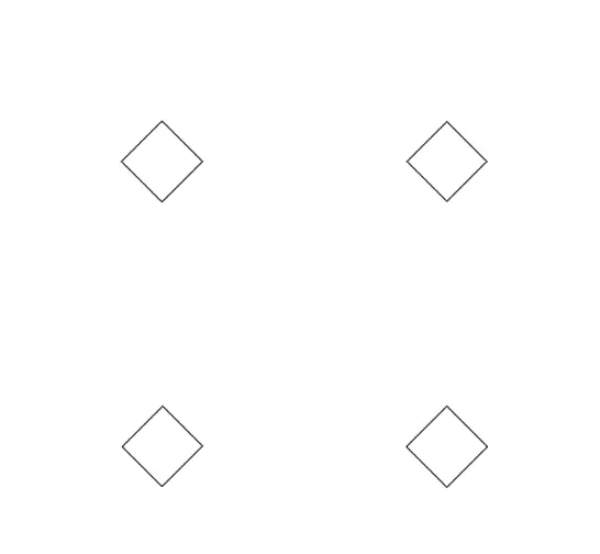
- Change the rotation degree using the slider as per requirement in the dynamo which is automatically reflected in the Revit screen as shown below.
Result :
Therefore, array of the model element such as column is created in Revit and model element is rotated by using integer slider in the dynamo as shown below.
4) Create a conceptual mass in Revit and develop a parametric column by dividing the surfaces and apply the concepts similar to used in parametric walkway modelling. Use triangular bent or square shaped panels to add finish to the parametric column.
Aim : To create a conceptual mass in Revit and develop a parametric column by dividing the surface using triangular bent pattern.
Introduction :
- Conceptual mass in Revit is 3D mass modelling.
- One of the purpose of mass modelling is to create 3D models of the odd shape building.
- By using this 3D modelling process we can create base of any odd shaped building.
Procedure :
Step 1
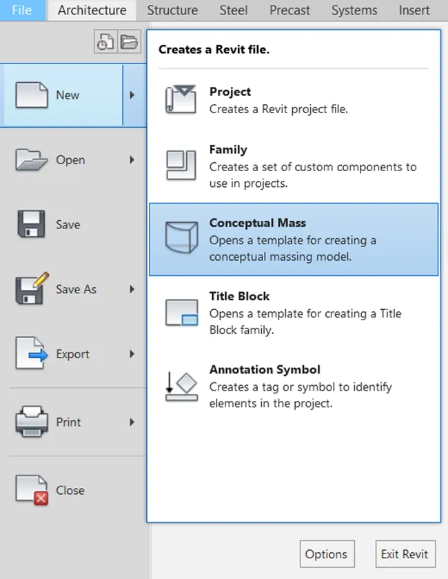
- Open the Revit software, go to file menu, select new and select conceptual mass from the file dialog box.
Step 2
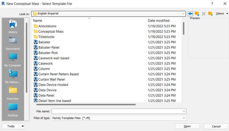
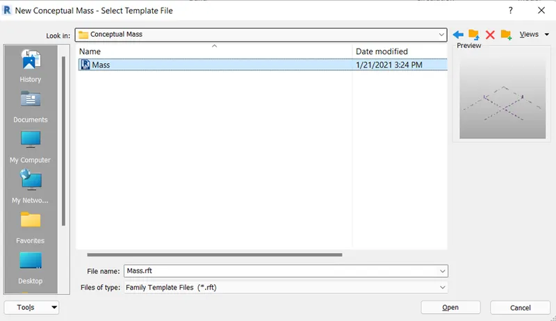
- Select the conceptual mass from English dialog box and select metric mass and select metric mass from select template dialog box.
Step 3
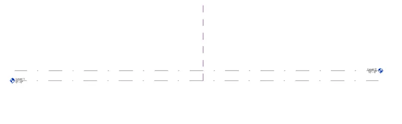
- Select the east elevation view and select the levels from datum panel and set the offset distance as 10’ and select pick line tool from draw panel.
Step 4
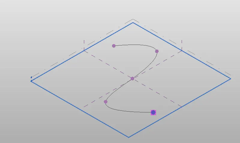
- Select the spline through points from draw panel and draw the spline curve by tracing the points as shown below.
Step 5
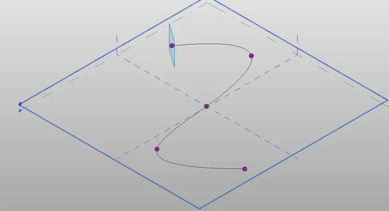
- Select the set work plane tool from modify window and set the work planes at each points as shown below.
Step 6
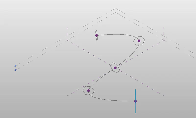
- Select the circumscribed polygon from draw tool and draw the polygon at each point as shown below.
Step 7
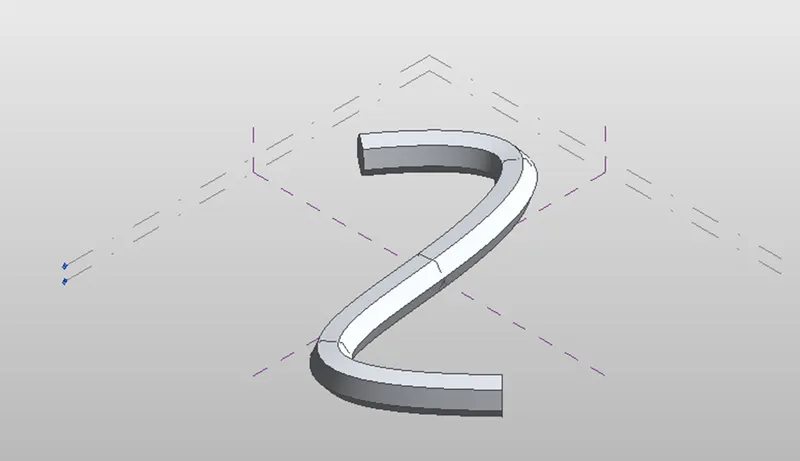
- Select the created polygon and spline curve and select create form panel of modify lines panel as shown below.
Step 8
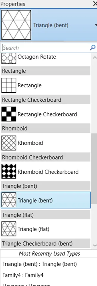
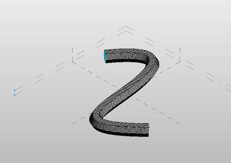
- Select the created model and select divide surface tool from divide panel of modify form tab and change the pattern to triangular bent from properties browser.
Step 9
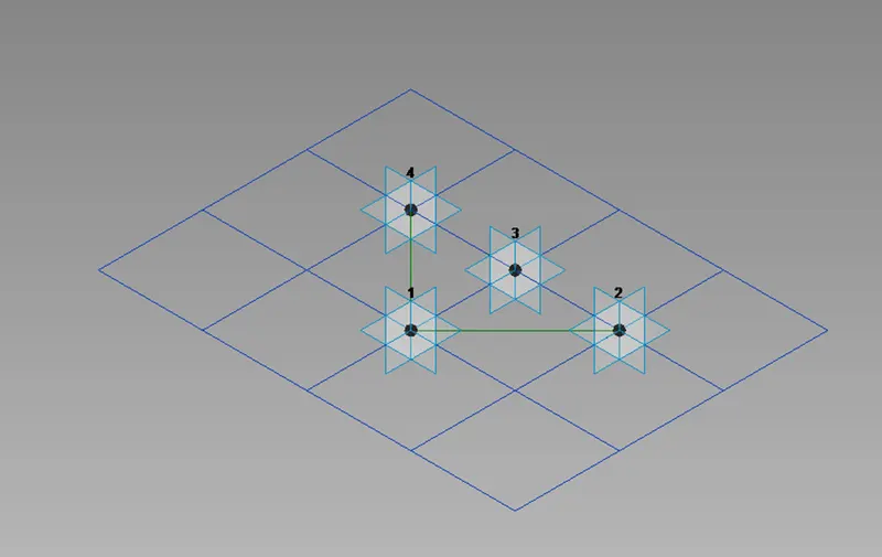
- Go to file tab and select new followed by family from file dialog box and select curtain panel pattern based wall, select the grid pattern, and select the hexagon pattern from properties window.
Step 10
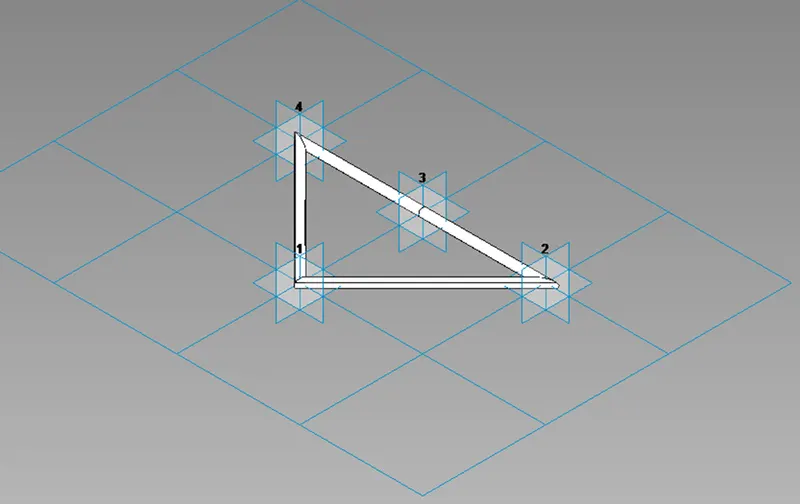
- Select the set work plane tool and set the plane at the one of the point on the triangle and draw the circle and create the form as shown below.
Step 11
- Select the load into project and load the hexagon pattern in the current project.
- Select the created mass and change the pattern to added triangular bent family pattern.
Result :
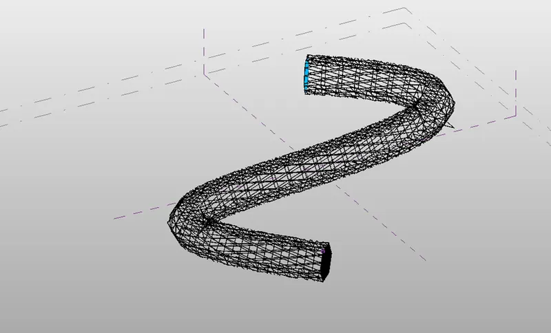
Therefore, conceptual mass in the Revit is created by developing the parametric column and the surface is divided as shown below.
5) Use Dynamo to work on developing a Parametric Stadium. List your parameters and use the visual programming approach to complete the modelling, You can use the concepts discussed in parametric high rise tower in class for reference.
Aim : To work on developing on the parametric stadium using dynamo and to use visual programming approach to complete the modelling.
Introduction :
- Parametric modelling is the creation of a digital model based on series of pre-programmed rules which is known as parameters.
- In this model or element is generated automatically by internal logical arguments rather than by being manually manipulated.
Procedure :
Step 1
- Open the Revit software and select dynamo tool from manage tab from visual programming panel.
Step 2
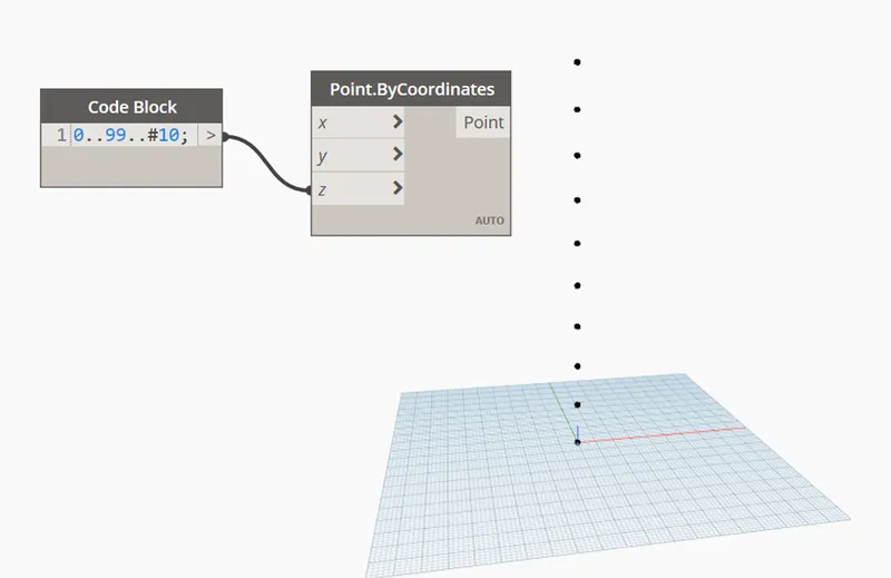
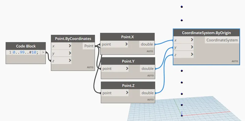
- Type point in the library browser and insert the point node along with the code block and set appropriate value in the code block node in the dynamo as shown below.
Step 3
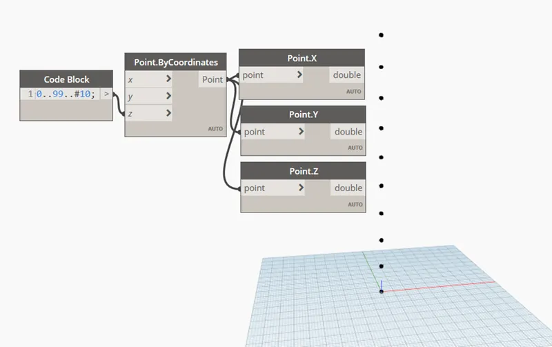
- Type point in the library browser and add the X point, Y point and Z point node as shown below and make appropriate wiring of the nodes as shown below.
Step 4
- Type origin in the library browser and add the point ByOrigin (x,y, z) node and make appropriate wirings of the nodes as shown below.
Step 5
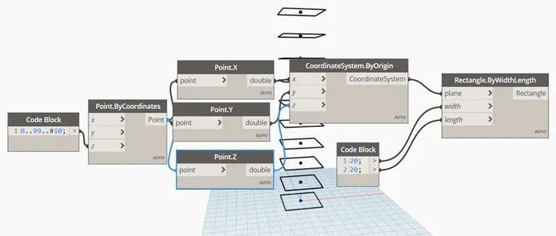
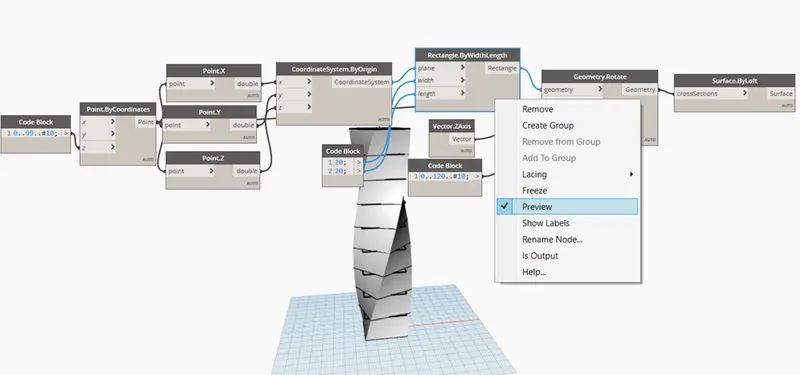
- Type rectangle in library browser and add rectangle by width and length node and make appropriate wiring of nodes as shown below.
- Add code block and set appropriate values to length and width of rectangle in the code block.
Step 6
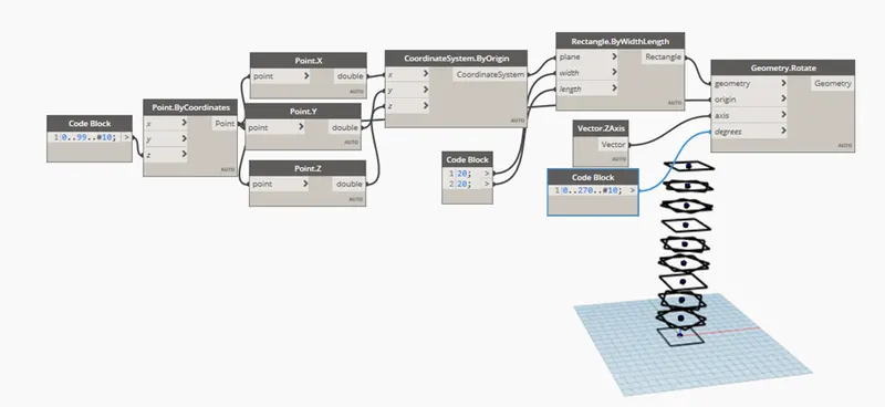
- Type geometry rotation and select rotation(origin, axis, rotation) from library browser and add the rotation node by making appropriate wiring.
Step 7
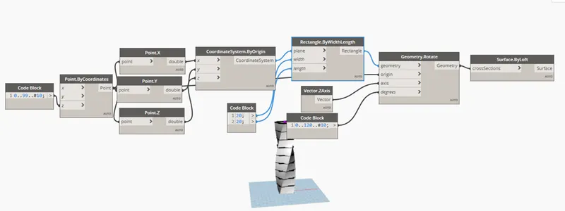
- Type surface and select surface by loft option from library browser and make appropriate wirings as shown below.
Step 8
- Select the rectangle node and right click on mouse. Select preview option from list as shown below.
Result :
Therefore, parametric stadium is developed by using the Dynamo as shown below.
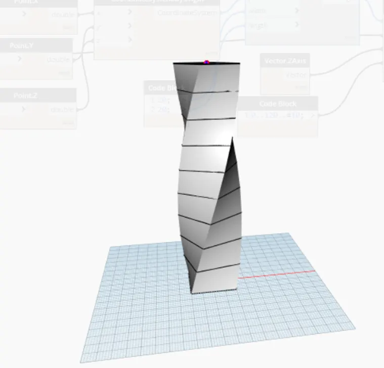
Plan view in Revit is shown below.