Creating Conceptual mass in REVIT and Creation of Sinusoidal curve and a Parametric stadium using Dynamo
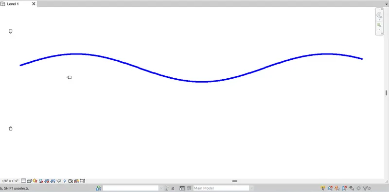
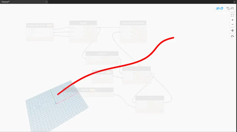
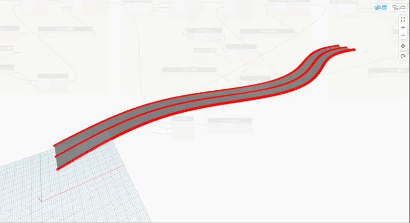
1) Using Dynamo creates a set of sinusoidal points and create a curve and create a surface out of the curve.
STEPWISE PROCEDURE:
- Open The Dynamo linked to your Revit File
- Open an Architectural template in Revit.
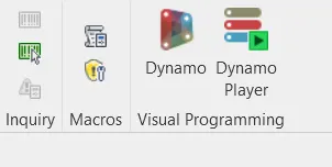
- Go to the Manage tab and click on the Dynamo logo to enter the Software.
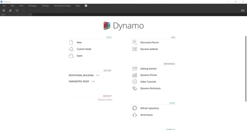
- A typical Dynamo intro page will be loaded on your screen.
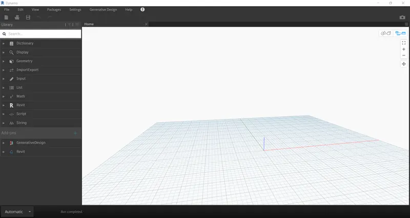
- Now, you can open up a new Dynamo project to create the required sinusoidal curve.
- Create a Range of Points in the X-Axis to Locate the Sinusoidal Curve
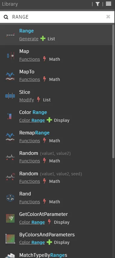
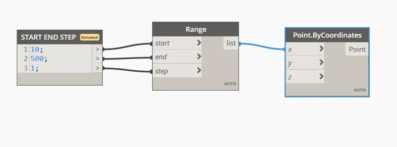
- In the search panel, type in the range command and insert the same into your Dynamo project.
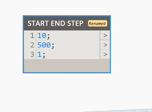
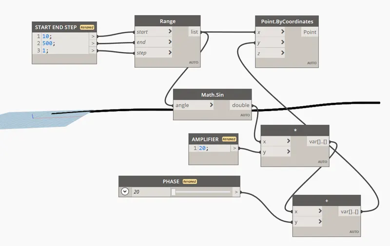
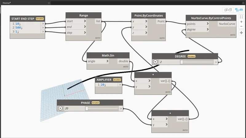
- Then, you will need three values as such start, end, and step. So, create a code block defining these three values.
- You can type in manually the code block in the search panel or you can also double click on the Dynamo screen and a code block shall be automatically generated for you.
- Assign the relevant range of values in the X-axis for the sinusoidal curve and attach the same to the coordinate point system.
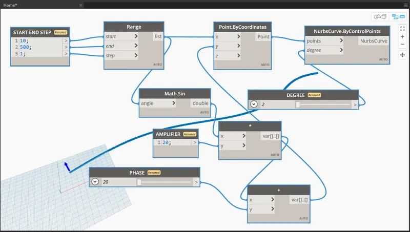
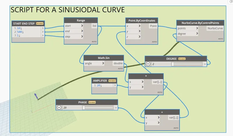
- Attach the range to the x point in the points by coordinates node. Thus, the range of points for your curve will be created.
- Create the Sinusoidal Function for the Curve
- Since we are aiming at the sinusoidal curve, we have to insert the sin function for the same.
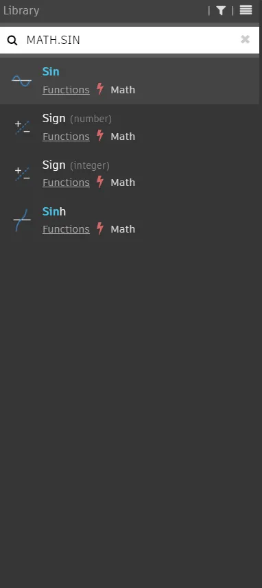
- And to do that, just type in the Math.sin command to insert the sin function node and attach the same with our range.
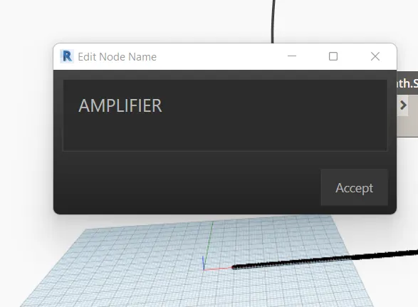
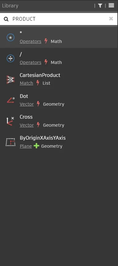
- However, the sin value for our range is going to be a lot less than what we need. Hence, we will attach an amplifier for it.
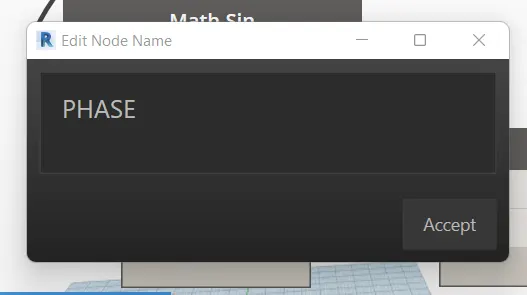
- Then, the product of the sin value and the amplifier is added with the phase to define the curve phase.
- At last, the calculated sum is attached to the y axis to generate the sinusoidal path for our curve.
- Curve by Control Points
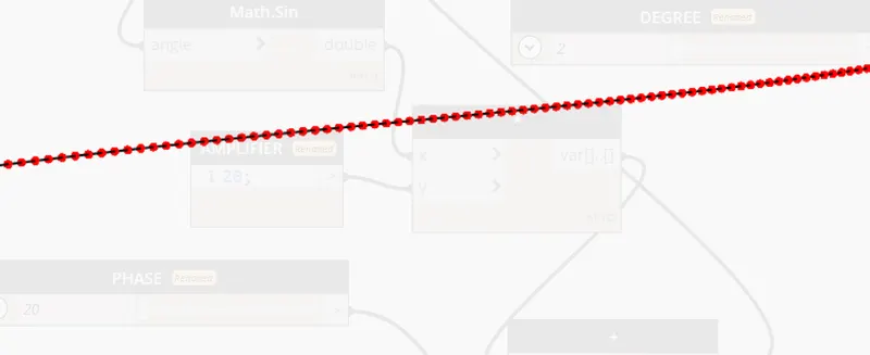
- Since we have laid down our points for the sinusoidal curve, now we can insert the node for the curve by control points.
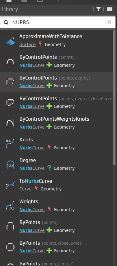
- And to do that, type in the NURBS curve in the search panel and insert the node.
- Now, you have to assign the degree for the curve so, insert the code block and define the curve degree.
- Create Two More Similar Curves with Different Phases
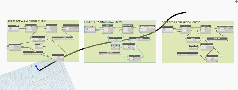
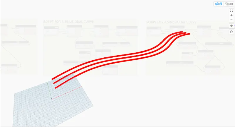
- To create a surface, we need more than one curve so, we will create a total of three curves for a sinusoidal surface.
- And to do so, just group all the nodes we created for a sinusoidal curve into a single script.
- Then, copy it down two more times within the Dynamo project.
- Now, change the phase for the copied scripts to form two more different curves.
- Create the Surface by Loft
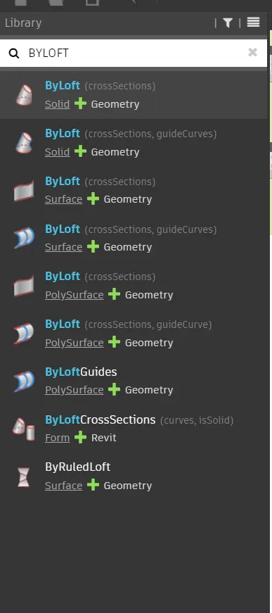
- Now we have all the curves required for the sinusoidal surface. Therefore, insert the surface by loft node into the project.
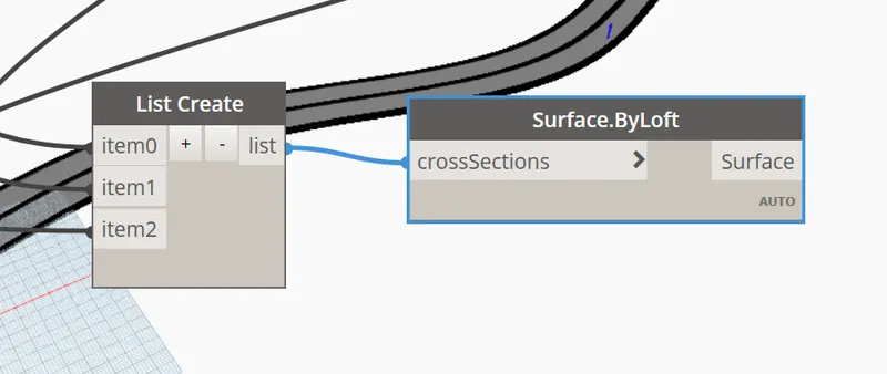
- However, we need to create a list of all the curves and then attach it with the surface cross-section.
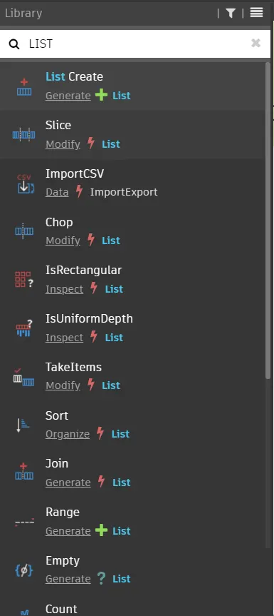
- So, type in the list command and insert the list.create node.
- Now, attach the list to the by loft node, and boom we're done.
- Hence, a sinusoidal surface is created using Dynamo.
FINAL OUTPUT:
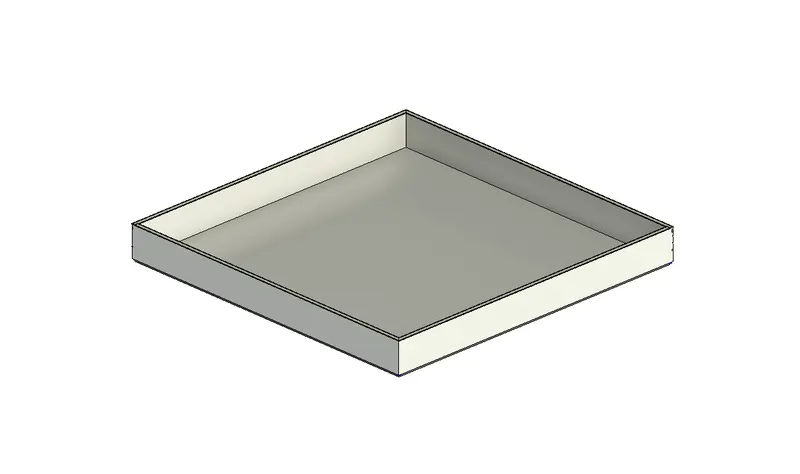
2) Create a conceptual layout of the floor plan in dynamo. Using the tools available in dynamo link the lines to appropriate model elements in Revit by choosing the wall types and wall parameters. Make use of the sliders to slide through the height of the wall and the length of the wall.
STEPWISE PROCEDURE:
- Insert the Points to Locate the Wall in Dynamo
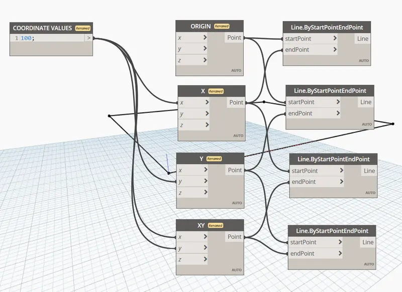
- We need four points to create a rectangular wall so we have to insert the relevant nodes for the same.
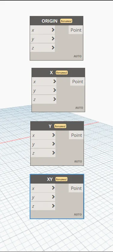
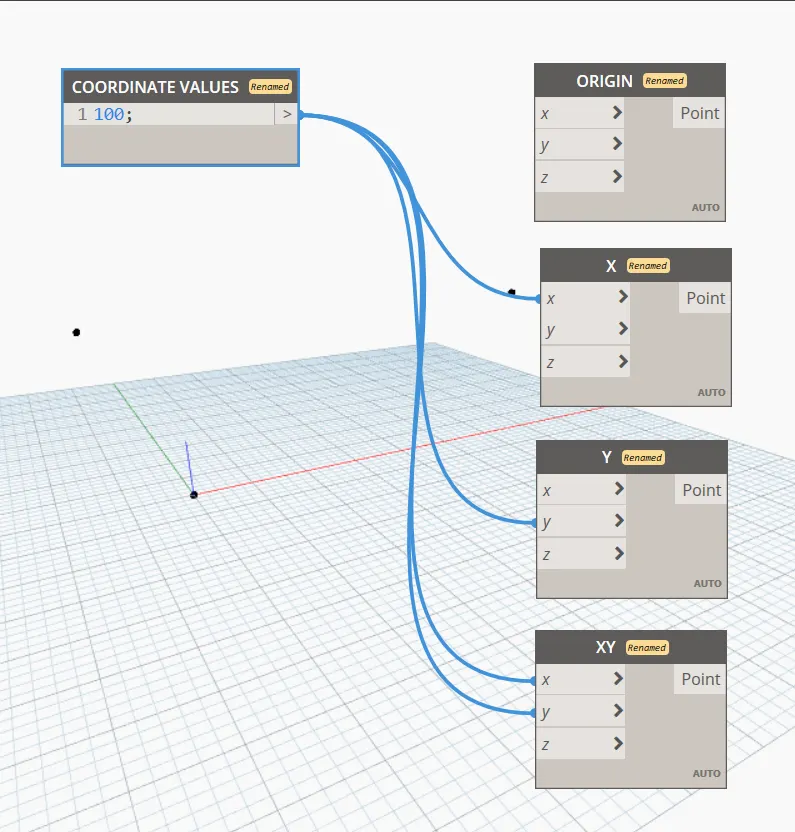
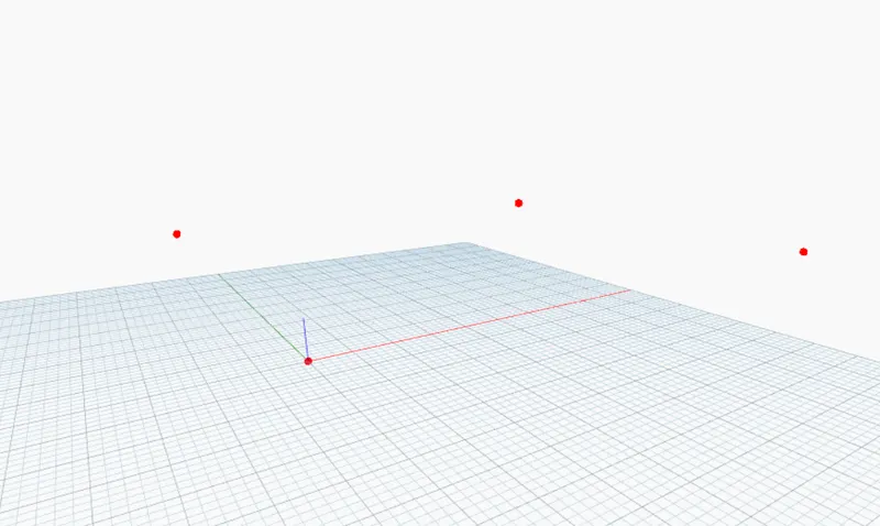
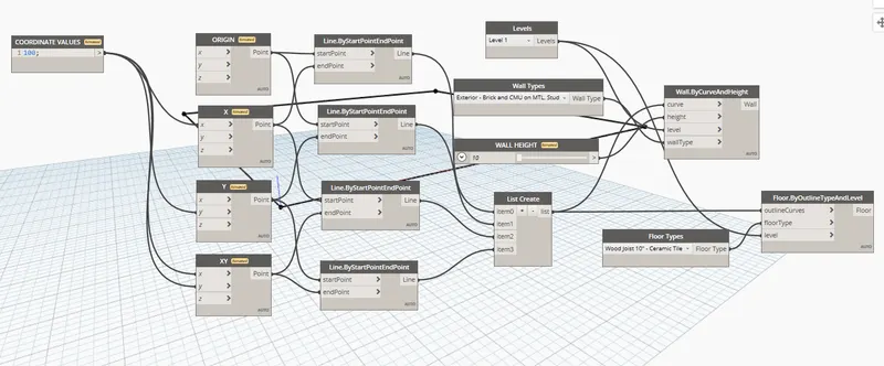
- So, insert four points by coordinates and then assign the values in both X and Y directions to create a rectangular layout.
- Also, keep one point for the origin and assign relevant values to all three points in a stepwise manner using the code block.
- Create the Lines Using the Four Points
- Now, insert the node that goes by the name lines by start and endpoint.
- Then, attach all four points to all the four lines in a stepwise manner to form a rectangular line section.
- Define Wall Type, Height, and Level
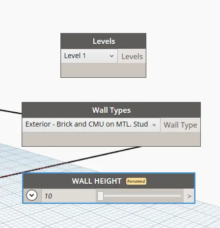
- Insert the node for the wall types and choose the accordant type from the dropdown list.
- Similarly, insert the node for levels and select the appropriate level that is level 1 for our current project.
- Now, insert an integer slider and define the wall height based on the project requirements.
- Then, minimize Dynamo and look up the result in your Revit screen.
- Wall by Curve and Height
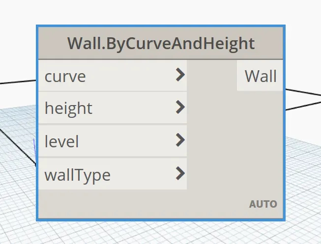
- Insert the node for the wall by curve and height.
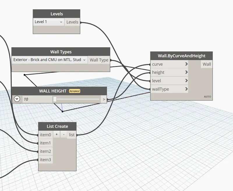
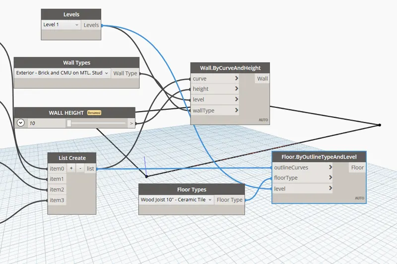
- Then, create a list of the lines that define our wall path and attach the same to the node.
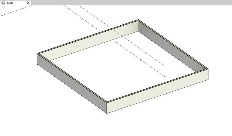
- Then assign all other required nodes like wall type, level, etc and complete the wall formation as follows:
- Floor Properties
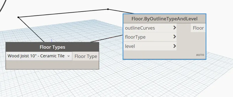
- Insert the node for floor types and look for the required values to create a floor within the boundary of our rectangular walls.
- Thus, follow the similar procedure which we followed in-wall creation and complete the script for the floor type, thickness, and other details.
- Lastly, minimize dynamo and look up the floor in your Revit screen to if it attached within the specified boundary or not.
FINAL OUTPUT
3) Create an array of model elements in Revit. Use dynamo to vary the properties of model elements by using the slider or code block
STEPWISE PROCEDURE:
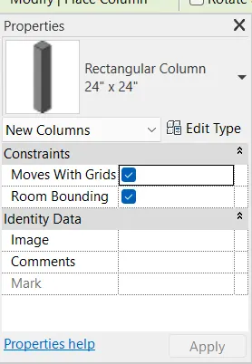
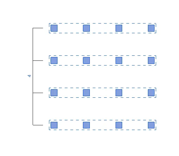
- Place an Array of Columns inside your Revit Project
- Open a new Architectural template.
- Go to the Architectural tab and select the columns and place it anywhere on the screen.
- Then, select the column and hit the "AR" Enter on your keyboard.
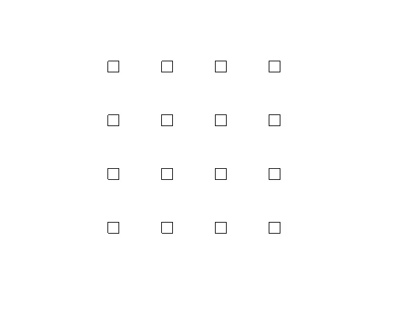
- Specify the number of columns and the distance at which you want the array to be executed.
- Adjust the array settings and finish up with the array of model elements creation.
- Open up the Dynamo Screen and Select Model Elements to be Edited
- Go to the Manage tab and hit the Dynamo option.
- Dynamo intro page will pop up, click on new to start a new Dynamo page.
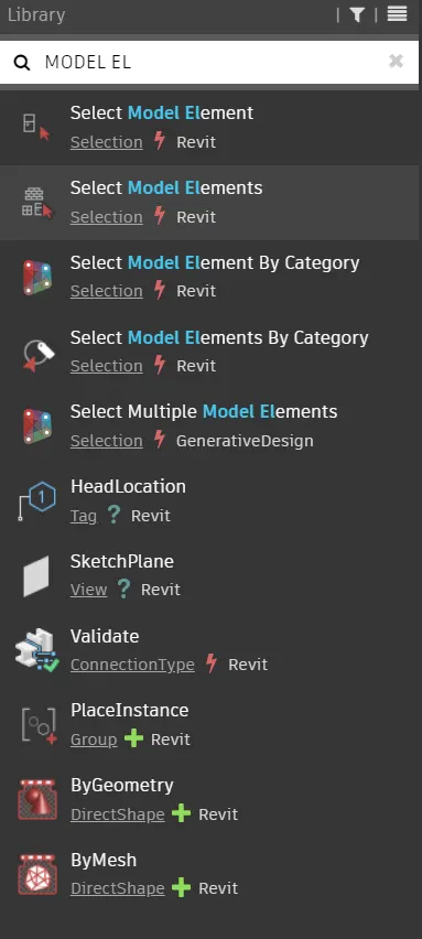
- Now, type in select in the Dynamo search panel and insert the select model elements node.
- Click on the select button within the node and come back to your Revit screen and select the array of columns that we have created in the previous step.
- Set Rotation
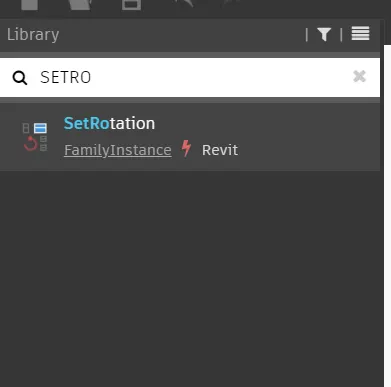
- Insert the node that goes by the name SetRotation.
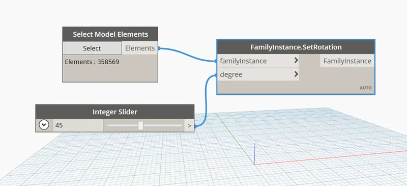
- It needs two values that are the family instances that are selected and the degree of rotation.
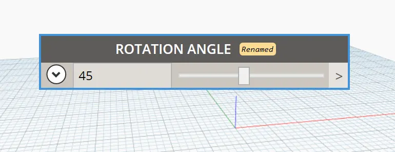
- So, you will have to insert an integer slider to define the rotation angle to edit the array of columns.
- Hence, insert the integer slider and specify the degree of rotation and attach the same to the set rotation node.
- Also, attach the selected family instances to the same node, and done your array of elements have been rotated to the degrees you have specified.
- Now, you can go back to your Revit screen and see that the edits have been executed successfully.
FINAL OUTPUT
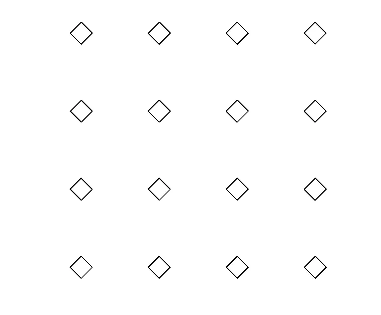
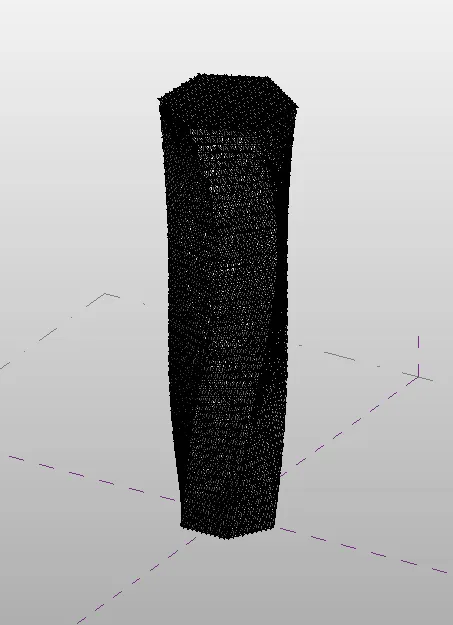
4) Create a conceptual mass in Revit and develop a parametric column by dividing the surfaces and applying the concepts similar to those used in parametric walkway modeling. Use triangular bent or square-shaped panels to add a finish to the parametric column.
STEPWISE PROCEDURE:
- Open a New Conceptual Mass Family in Revit
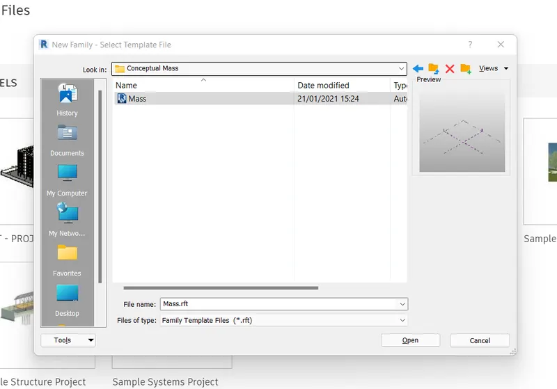
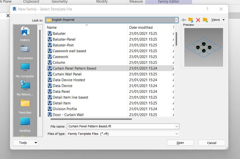
- Go to file<new<family and then select the conceptual mass file from the browse option.
- Set up the Conceptual Path for your Column
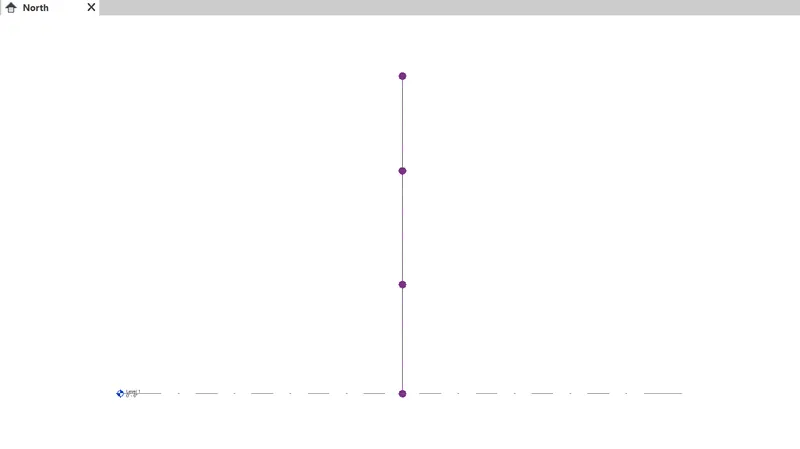
- Go to the north elevation and from the create tab, select the spline option to set up the column path.
- Now, set the base for the column and create the vertical path with different points.
- Define the 3D- Shape for your Column
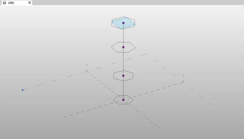
- Go to the 3d view and select the shape of your choice from the draw menu.
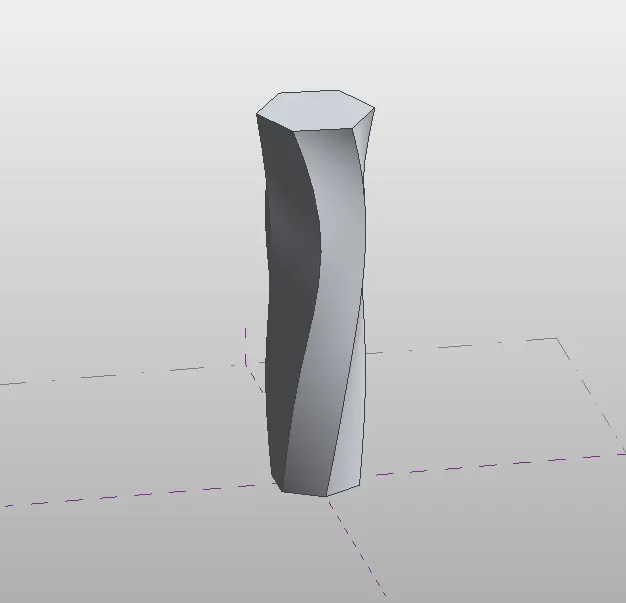
- For this instance, we have chosen the polygonal shape for our column.
- So, select each point within the column path, set the workplane, and create the polygon of an appropriate dimension based on the concept needs.
- Create From
- After setting up the shape, go ahead and select the spline and all of the polygons by using the control key on your keyboard.
- Then, you will see an option named create form within the top tools panel.
- So, click on it, and boom your column's conceptual shape will be automatically generated.
- Divide the Surface
- Now, select the entire column.
- Go to filter and uncheck everything except the form.
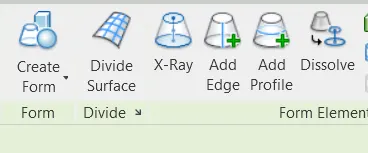
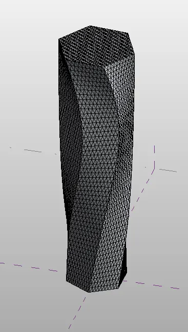
- Then, from the top tools bar, click on the divide surface.
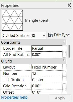
- Also, we have chosen a triangle bent form but you can choose the form of your choice.
- Create the Curtain Panels for the Column
- Open up a new Revit family and choose the file with the name curtain panel pattern-based.
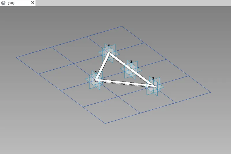
- Then, insert the triangle bent panels which we have chosen for our divided surface.
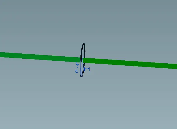
- Now, to create the circular panel, create a circle of 4" and create a form with the same like we did with the polygons while creating the column.
- So, the panel is ready and now you can load it into your conceptual mass project.
- Add the Curtain Panels to your Column's Conceptual Mass
- So, select the column sides one at a time and from the properties panel, select the newly created curtain panel family.
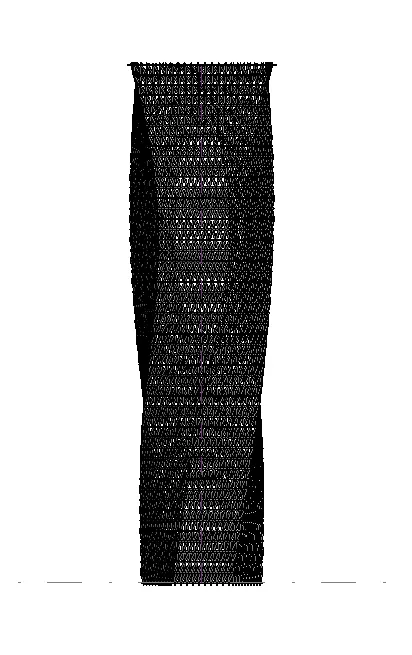
- Also, strictly make sure to select one column side at a time as selecting the entire section can create hurdles and make your Revit software lag big time.
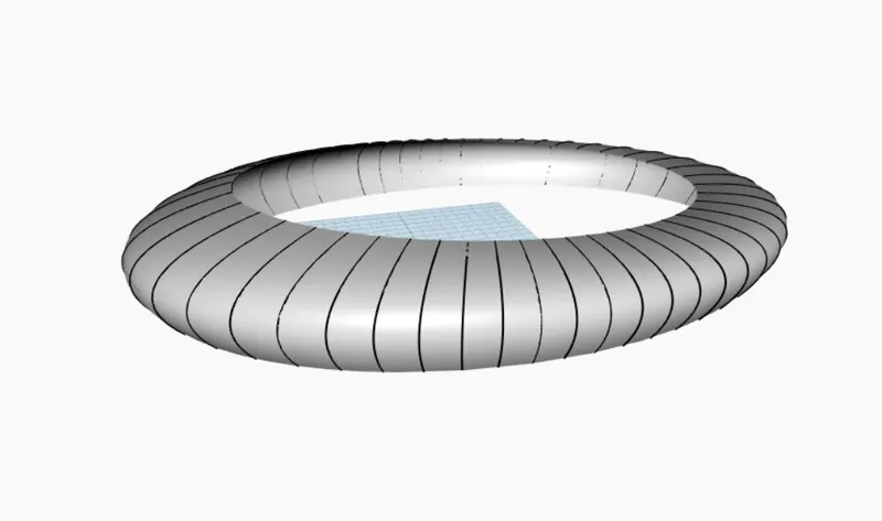
5) Use Dynamo to work on developing a Parametric Stadium. List your parameters and use the visual programming approach to complete the modeling, You can use the concepts discussed in parametric high rise tower in class for reference.
COMPLETE STEPWISE PROCEDURE TO CREATE A PARAMETRIC STADIUM USING DYNAMO:
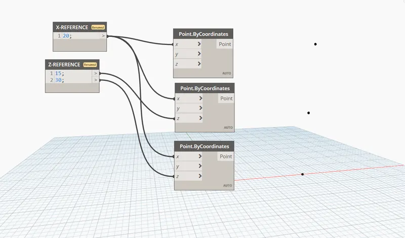
- Set up Three Base Points for the Stadium
- Insert three points by coordinates nodes from the search panel.
- Locate these points at a distance within the X-axis and vertically in a pre-defined range of Z-axis through the code block.
- Create Circles from the Base Points
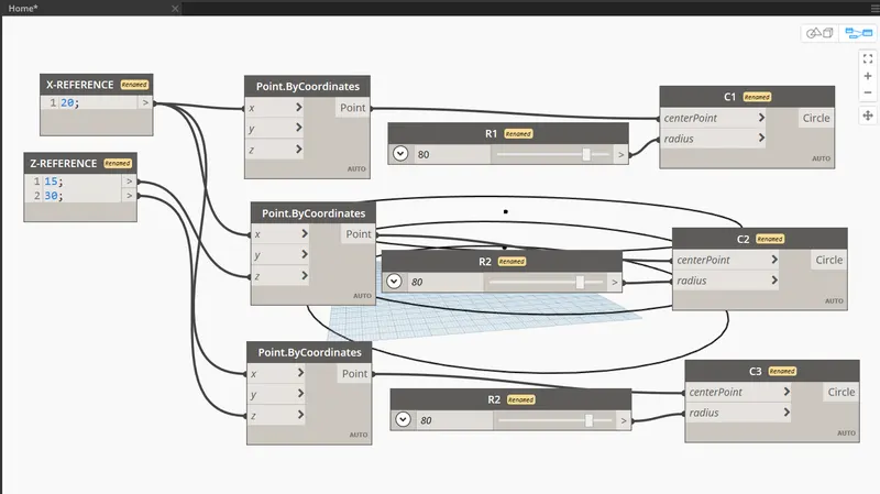
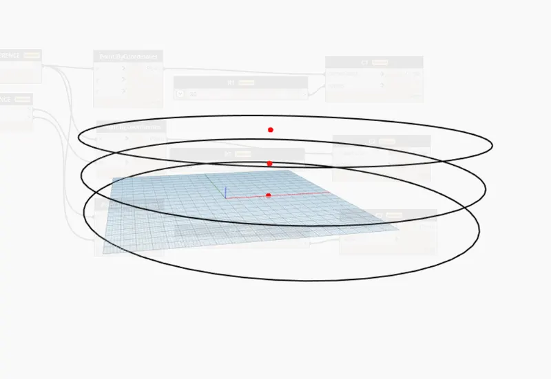
- Insert the node named circle by center point and radius.
- Also, insert different sliders for each radius as we will have to change the radius in the future based on the geometry of the stadium.
- Create the Surface by Loft
- Create a list of all three circles and attach the same to the surface by loft node.
- A circular surface will be created which will act as the base surface for our stadium.
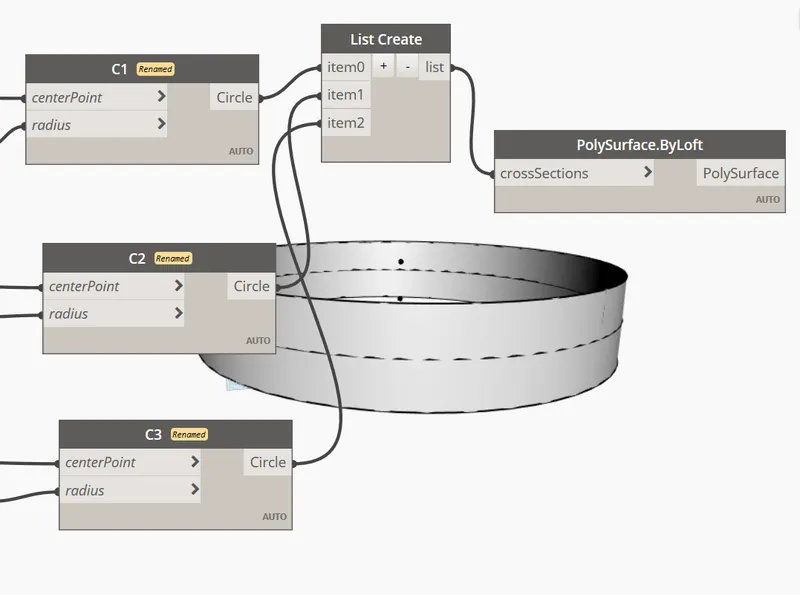
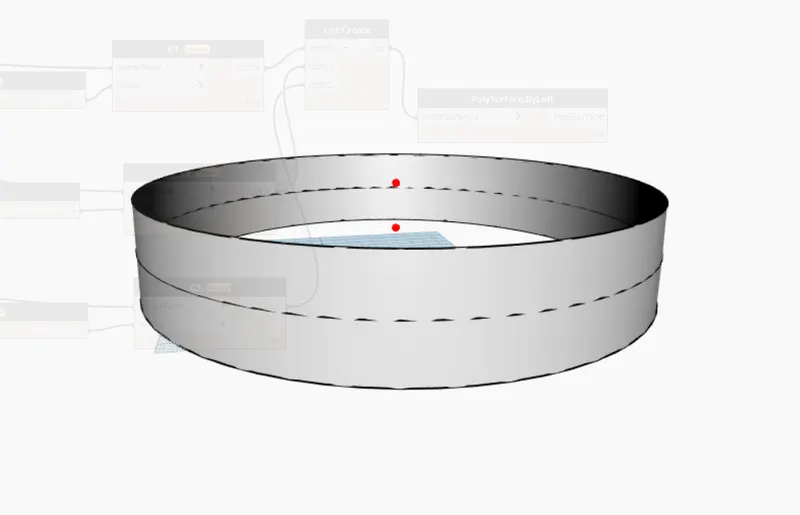
- Scale the Surace Geometry
- As you can see we have a basic circular surface which is not ideal for a parametric stadium. Therefore, we have to scale it as per the standard stadium design.
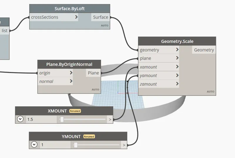
- And to do so, insert a node named scale.geometry into your dynamo project.
- Then, it will further need you to define the plane, surface, x mount, and y mount.
- So, set up the plane with the origin as the center point of our first circle.
- Moreover, the surface will be the basic circular stadium that we just created.
- Also, attach x and y amounts with the help of sliders as we will have to adjust them according to the stadium shape.
- Hence, after attaching all the nodes, manage the x and y mounts until the stadium takes an oval shape.
- Then, hide the basic circular geometry from the preview by right-clicking the same.
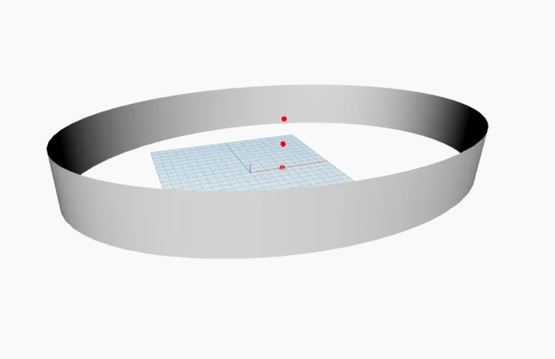
- Rotate the Stadium Geometry
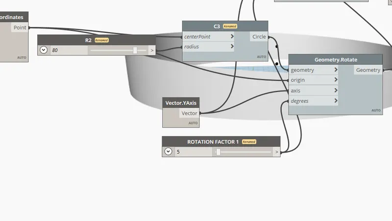
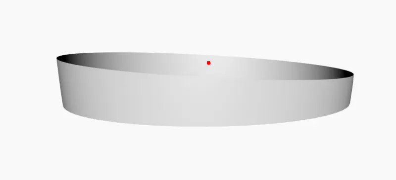
- Now to make the outlook of the stadium a bit more fascinating, we will rotate the stadium geometry from one side.
- So, insert the geometry. rotate node from the search panel.
- Now, you will need to attach the geometry, origin, axis, and degrees to execute the rotation successfully.
- To be more clear, we are rotating the circles we created, in the beginning, to make the stadium look a bit rotated.
- So, attach the geometry as one of the circles, then origin as the center point, axis as the Y-axis, and the degrees as the number slider.
- Adjust the Geometry Radius to Improve the Curvature Outlook
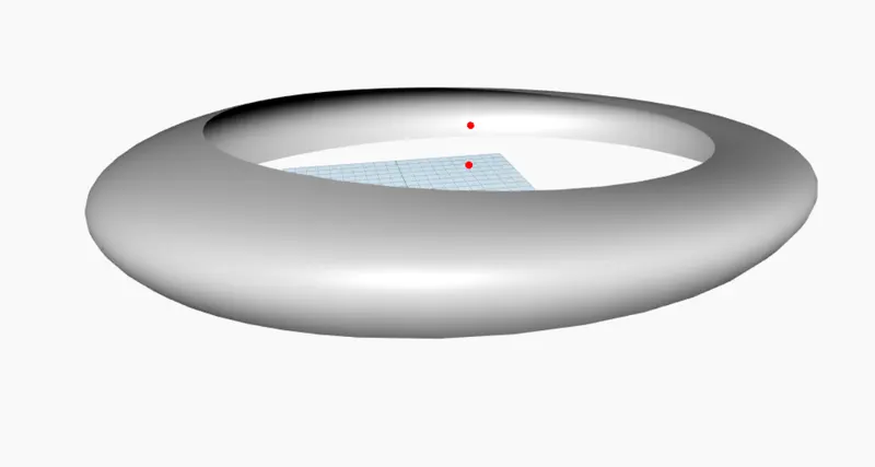
- Now, go back to the radius we assigned to the circles at the start.
- Assign a negative value to one of the radii and see the stadium take a curved form inside out.
- Assign the Segments to the Stadium
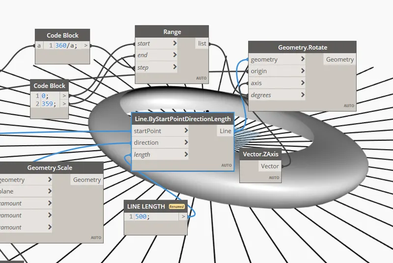
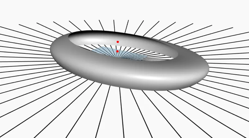
- Create a line from the start point, direction, and length.
- Give the start point as the center of our first circle, direction as y-axis, and the length as 500; via code block.
- Then rotate the line in a 360 degree throughout the stadium.
- And to do so, create a number slider and name it as a number of sliders and give it a 50 value.
- Then, create a range with start, end, and step.
- Now, create a code block for step and type in 360/a as the code.
- Assign the number slider for segments as 'a'.
- Attach 360/a code block to the step of range.
- And, attach 0 and 359 as start and end to rotating the line segment throughout the stadium.
- Make the segments intersect with the stadium
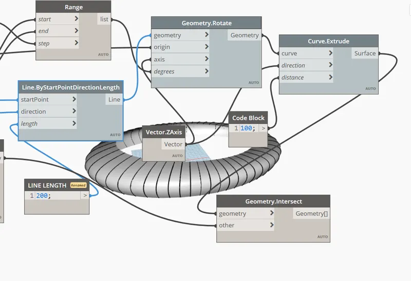
- First, extrude a curve in the Z-axis via the rotated line segments.
- Then, insert a node named geometry.intersect into the dynamo project.
- It needs you to attach two values that are geometry and another cross-section you want to intersect with.
- So, give geometry as the rotated line segments and other as our scaled geometry, and done it will be successfully intersected.
- Now, hide a preview of all the unnecessary elements from the dynamo screen and make the stadium visible crystal clear.
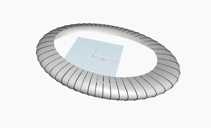
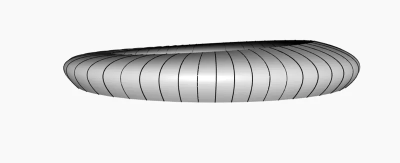
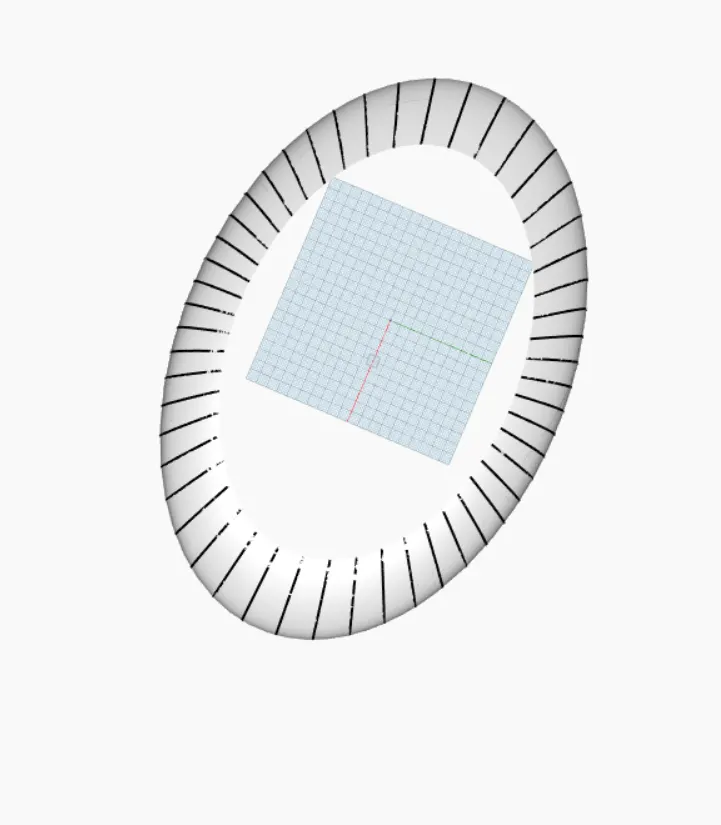
- So that's it, a parametric stadium geometry outlook has been completed using dynamo.
FINAL OUTPUT