Creating Bar Bending schedule, Different Door types, and Creation of standard drawing templates using AutoCad
1.
AIM:
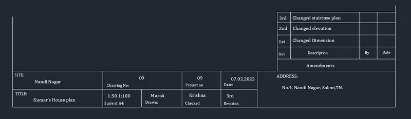
To create the templates as shown in figure, add texts, attributes and save the templates as blocks with names custom titleblock 1 and custom titleblock 2. Explain the procedure step by step and show the result.
INTRODUCTION:
AutoCAD is a computer aided design software and drafting software application.
In this project, I have used various commands like,
* Line, XLine, Join - to create the objects
* DText - to mention texts
* Block definition - to create blocks
* Attribute definition - to create attributes
* Copy - to create objects.
* Fillet, Trim/erase, Offset, trim, ED - are regularly used at various places to complete the diagrams.
In the next step, the procedure is explained perfectly.
PROCEDURE:
- Open AutoCAD software
- Start from scratch
- Set the units to engineering and select ok
- Set limits as lower left corner (0,0) and upper right corner (500',500')
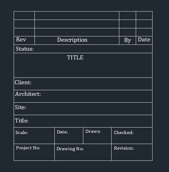
- First, I have created the table and mentioned the texts wherever required.
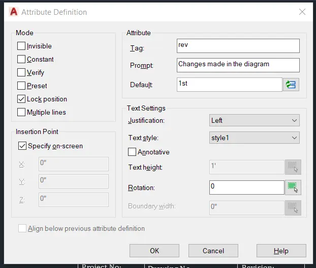
- Using Attribute Definition, I have created a tag named Rev(revision) with prompt as changes made in the diagram and default as 1st.
- Checked all other requirements and selected OK.
- The insertion point was specified on screen.
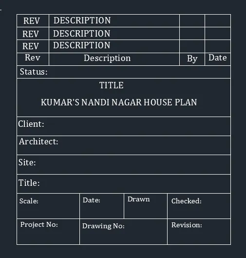
- The following image shows that I have created a total 6 attribute definitions ( 3 as Rev Tags and 3 as Description tags).
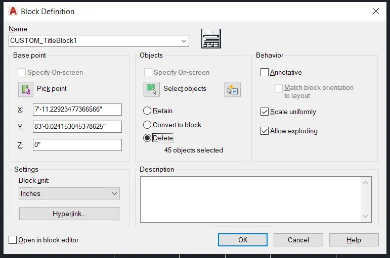
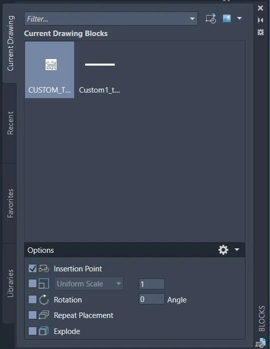
- Then, using Block definition I have selected the whole Template, picked a base point and named the block as CUSTOM_TitleBlock1.
- Using INSERT Command, I have selected the CUSTOM_TitleBlock1 and inserted it on the screen where i required.
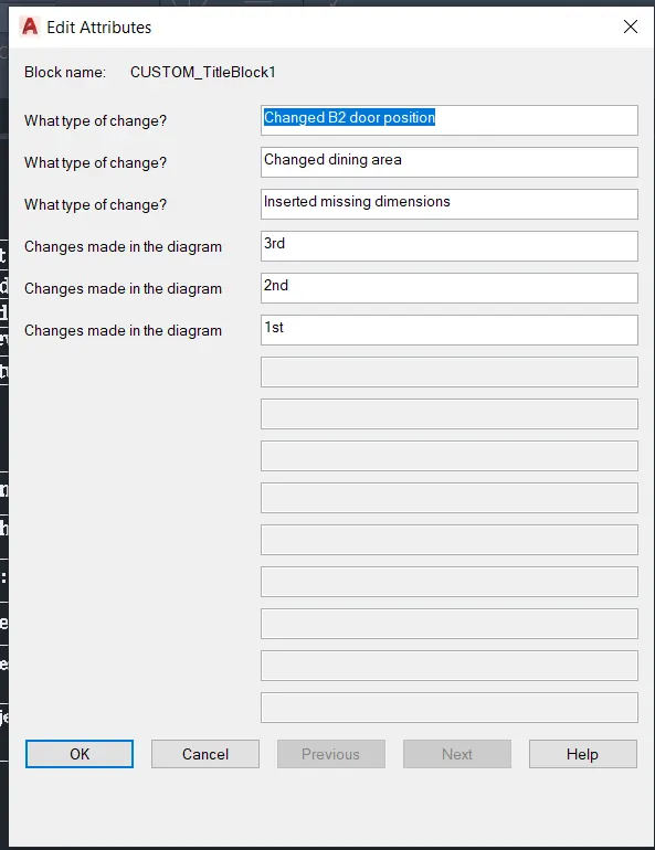
- These are the attributes I have created in this block and the EDIT ATTributes allows me to make any changes in the last before inserting the block on the screen.
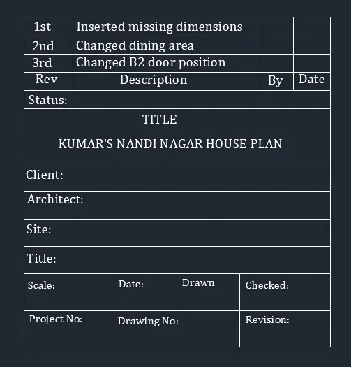
- The Following Image shows the Final output of REV and DESCRIPTION attributes after inserting the block on the screen.
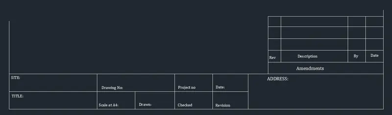
- Similarly, for the second diagram too, I have created the table and mentioned the texts wherever required.
- In the Next step, I have added ATTRIBUTES using Attribute Definition.
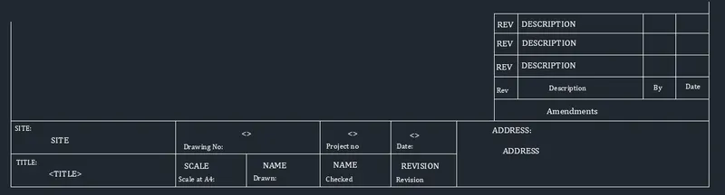
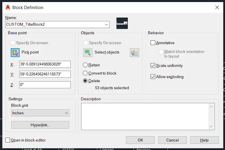
- Using Block Definition I have selected the whole template, picked a base point and named the block as CUSTOM_TitleBlock2.
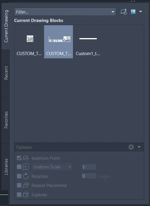
- Using INSERT command, I have selected the block CUSTOM_TitleBlock2 and inserted it on the screen
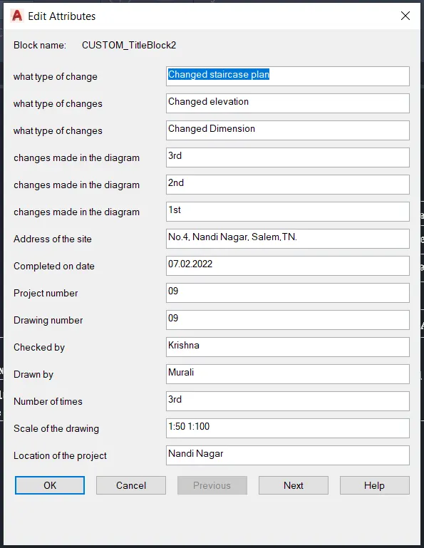
- The following image shows all the Attributes that i have created in this block.
- This is the final output after the block with attributes is inserted.
RESULT:
2.
AIM:
To create the warehouse door blocks as shown in the figure, explain the procedure step by step and display the result.
INTRODUCTION:
AutoCAD is a computer aided design software and drafting software application.
In this project, I have used various commands like,
* Line, XLine, Join - to create the objects
* Block definition - to create blocks
* Copy - to create objects.
* Fillet, Trim/erase, Offset - are regularly used at various places to complete the diagrams.
In the next step, the procedure is explained perfectly.
PROCEDURE:
- Open AutoCAD software
- Start from scratch
- Set the units to Decimal and select ok
- Set limits as lower left corner (0,0) and upper right corner (500',500')
- Using the commands,
Line, Polyline, Xline, Offset, Fillet and trim, I have created the door type 1.
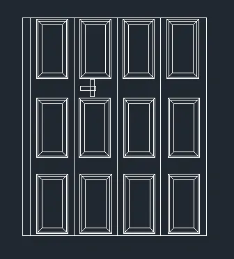
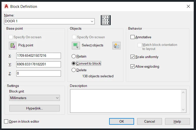
- Using Block Definition, I have selected the whole door, picked a base point, named the block as DOOR 1 and convert to Block.
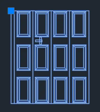
- The following image shows the DOOR 1 as a single block object with the base point in the top left.
- Similarly, Using the commands,
-
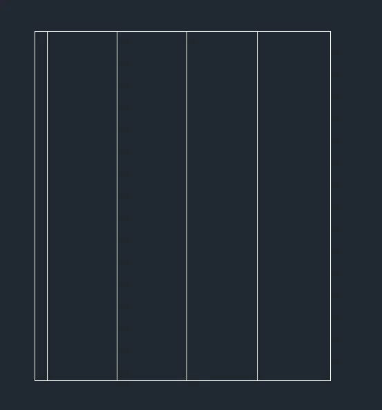
Line, Polyline, Xline, Offset, Fillet and trim, I have created the door type 2.
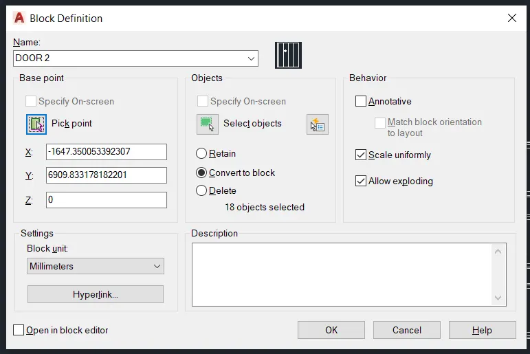
- Then, Using Block Definition I have selected the whole door, picked a base point, named the block as DOOR 2 and convert to Block.
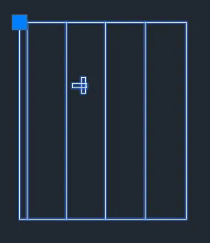
- The following image shows the DOOR 2 as a single block object with the base point in the top left.
RESULT:
Warehouse Doors as Single blocks.
3.
AIM:
To create each symbol as a block with names given in the legend and insert them and create a complete legend as shown in figure. Explain the procedure step by step and display the result.
INTRODUCTION:
AutoCAD is a computer aided design software and drafting software application.
In this project, I have used various commands like,
* Line, XLine, Circle, Hatch, Join - to create the objects
* DText - to mention texts
* Block definition - to create blocks
* Field - to insert names of the blocks in the table.
* Copy - to create objects.
* Fillet, Trim/erase, Offset, trim, ED - are regularly used at various places to complete the diagrams.
In the next step, the procedure is explained perfectly.
PROCEDURE:
- Open AutoCAD software
- Start from scratch
- Set the units to engineering and select ok
- Set limits as lower left corner (0,0) and upper right corner (500',500')
- Using the commands,
Line and circle, I have created the Single Gang Switch as shown in figure.

- Using Block Definition I have selected the whole switch diagram, picked a base point, named the block as SINGLE GANG SWITCH and convert to block.
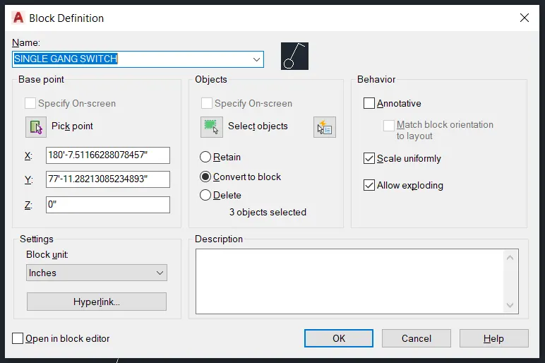
- Similarly, I have created all the symbols and using block definition i have converted them into blocks with names given in the legend.
- The following images shows the block definitions for two other symbols.
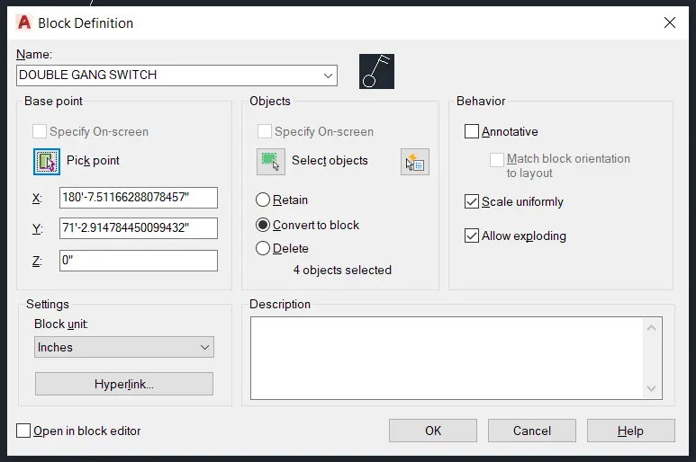
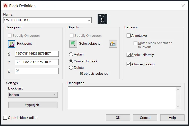
- The following image shows all the Symbols as blocks with names given in the legend.
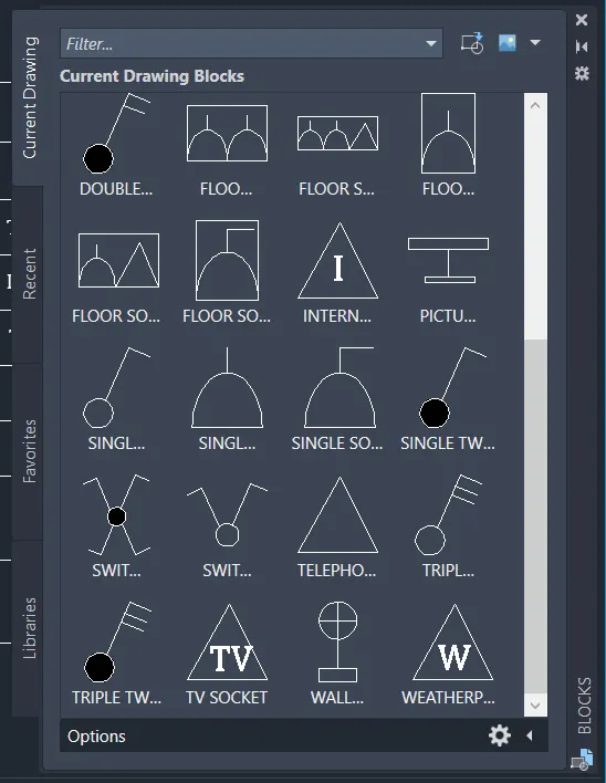
- After creating all the symbols and converting them into blocks, I created a tabular column with headings.
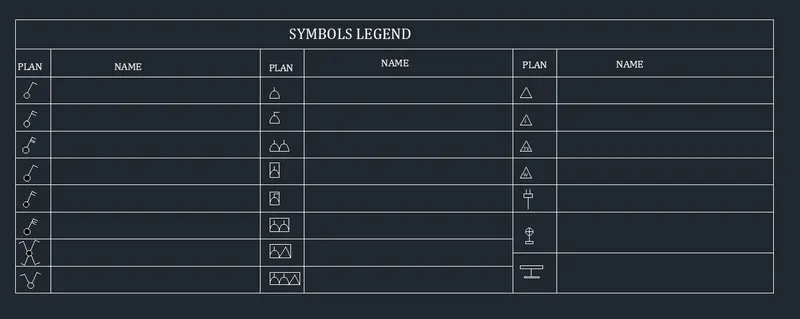
- Then, using FIELD Option, I have inserted the block names in the tabular column.
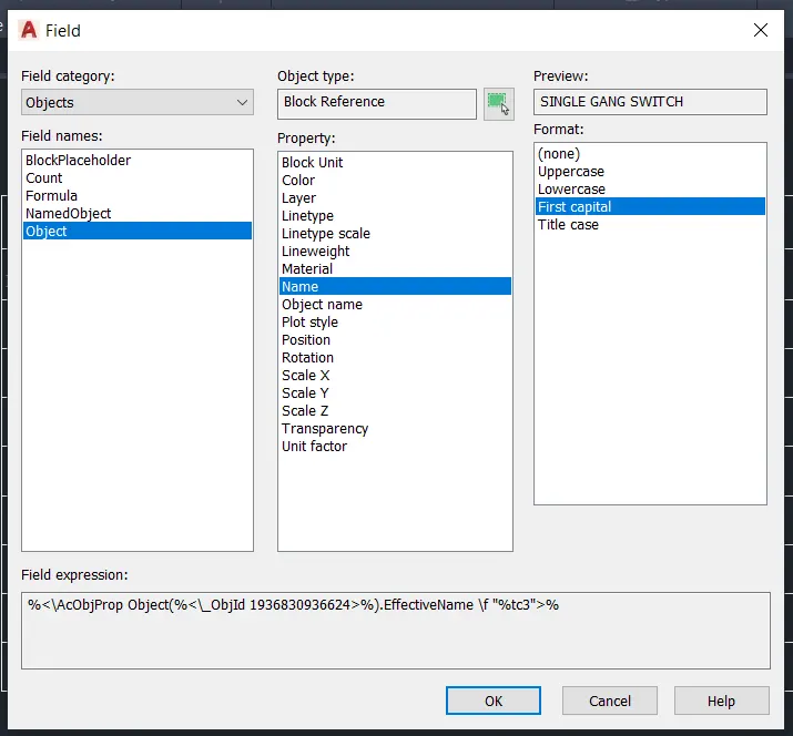
- This is the image of tabular column after using FIELD option to mention the block names.
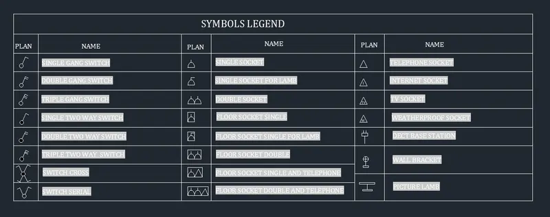
- In order to remove the shade behind the block names, Select all the names and EXPLODE it.
- This is the final image after the Block names are mentioned.
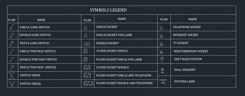
RESULT:
The complete legend with block symbols and its names
4.
AIM:
To create the door type for residential building as blocks and name the blocks as types. Explain the procedure step by step and display the result.
INTRODUCTION:
AutoCAD is a computer aided design software and drafting software application.
In this project, I have used various commands like,
* Line, XLine, Polyline, Join - to create the objects
* Block definition - to create blocks
* Copy - to create objects.
* Fillet, Trim/erase, Offset - are regularly used at various places to complete the diagrams.
In the next step, the procedure is explained perfectly.
PROCEDURE:
- Open AutoCAD software
- Start from scratch
- Set the units to engineering and select ok
- Set limits as lower left corner (0,0) and upper right corner (500',500')
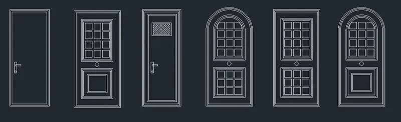
- Using the Commands Line, Polyline, Circle, Offset and join, I have created the following door as shown in fig.

- Using Block definition, I have selected the entire door, picked a base point, named the block as DOOR TYPE 1 and convert to Block.
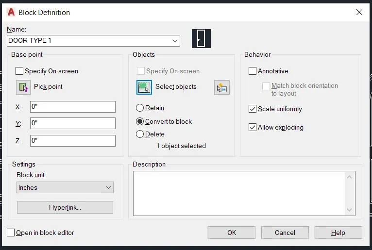
- Similarly, I have created all the other doors and converted it to blocks and named them.
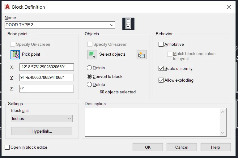
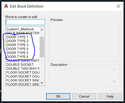
- Using INSERT command, I have inserted all the door types that i have created in this diagram.
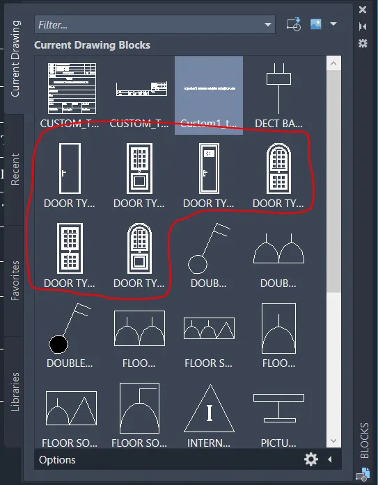
- This is the final output after doors being converted into single blocks.
RESULT:
The following images shows that the doors have been converted into blocks and names are given as types.
5.
AIM:
To create each bar bending shape as a block and insert them in the table like shown in the figure. Explain the procedure step by step and display the result.
INTRODUCTION:
AutoCAD is a computer aided design software and drafting software application.
In this project, I have used various commands like,
* Line, XLine, Join - to create the objects
* DText - to mention texts
* Block definition - to create blocks
* DIM Lin - to mention the dimensions
* Copy - to create objects.
* Fillet, Trim/erase, Offset, trim, ED - are regularly used at various places to complete the diagrams.
In the next step, the procedure is explained perfectly.
PROCEDURE:
- Open AutoCAD software
- Start from scratch
- Set the units to Decimal and select ok
- Set limits as lower left corner (0,0) and upper right corner (500',500')
- Using the commans Line, Dtext and DIM LIN, I have created the first bar bending shape as shown in figure.
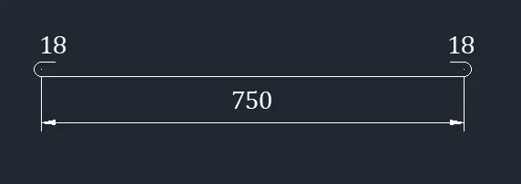
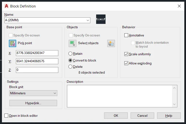
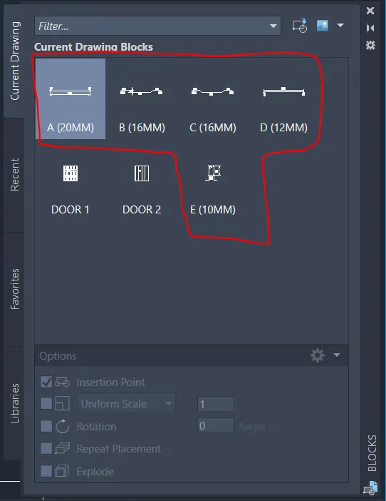
- Then, using Block definition I have selected the entire shape, picked a base point, named as block A(20MM) and deleted it to insert later after creating the table.
- Similarly, I have created all the shapes and converted it into blocks and named them.
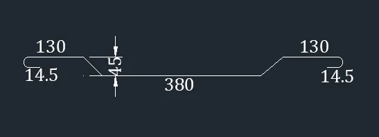
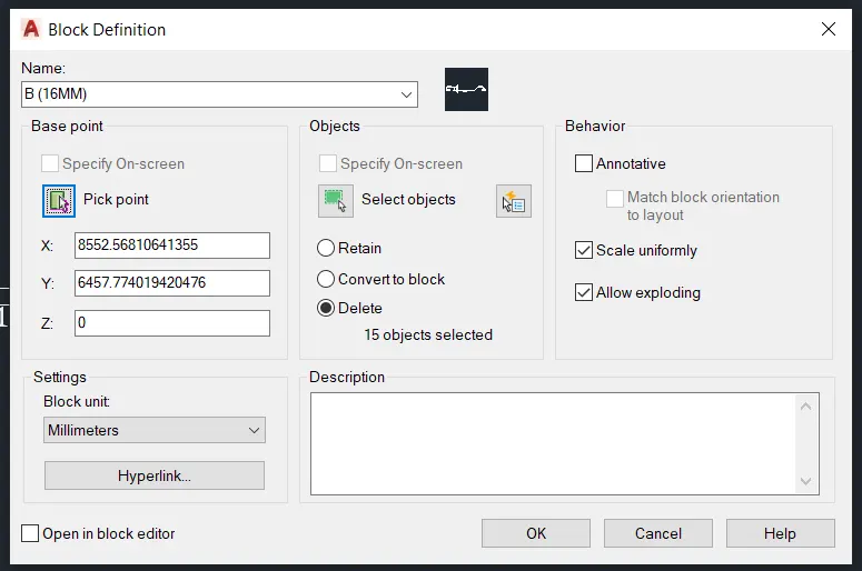
- The following mark in the image shows the block shapes that i have created.
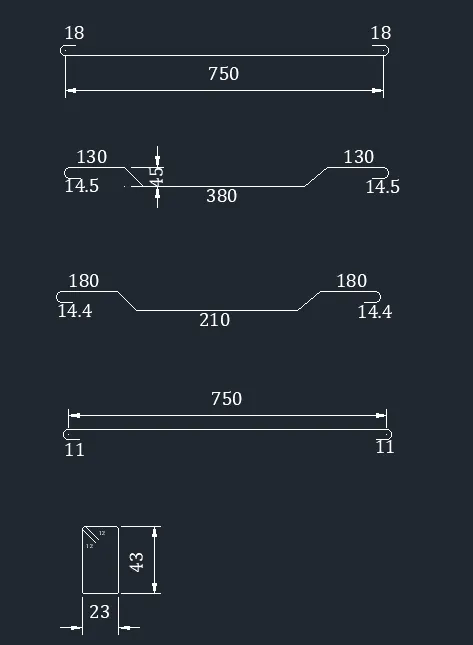
- Using INSERT command, I have inserted all the block shapes in the screen.
- Then, using the commands
Line, Offset, Fillet, Trim, and Dtext, I have created the tabular column as shown in figure.
Using FIELD Option, I have inserted the Block names.
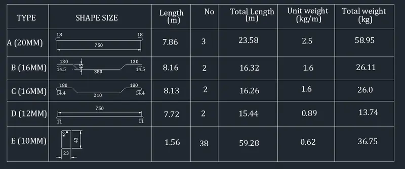
RESULT: