Creating Bar Bending schedule, Different Door types, and Creation of standard drawing templates using AutoCad
Q1
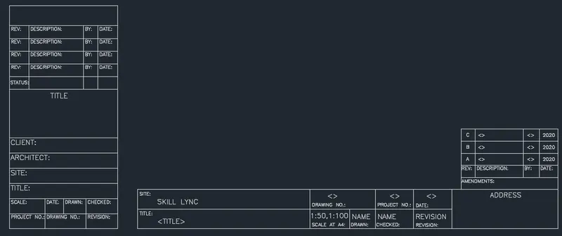
AIM : To Create the templates as shown in Figures.
PROCEDURE
STEP 1 :
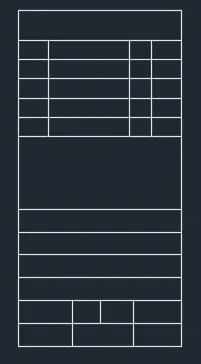
Type L or line in the command box and press enter
Draw the table as per the given figure
STEP 2 :
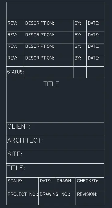
Type DTEXT in the command box and press enter
Add the text where ever required
STEP 3 :
Type B or block in the command box and press enter
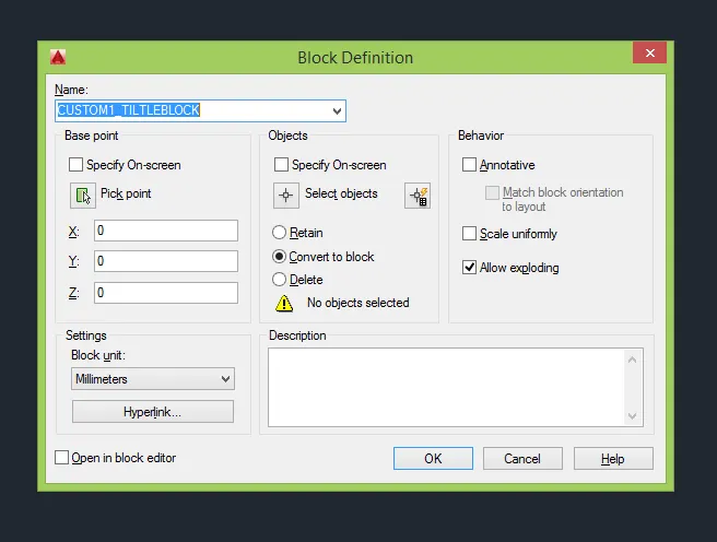
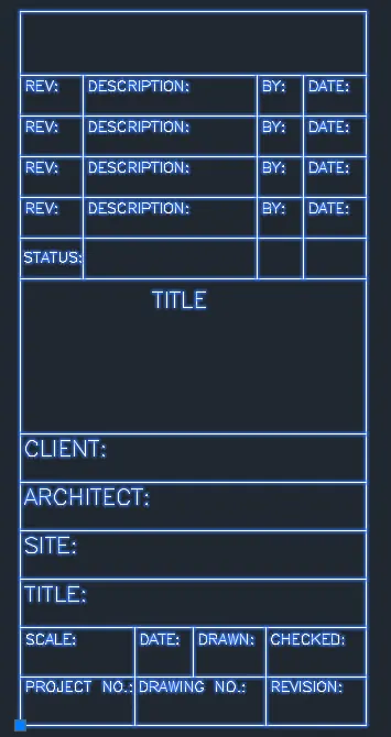
Give the name as CUSTOM1_TITLEBLOCK and pick the point from the AutoCAD screen and press enter and select the object from the screen and press enter
Block is been created
STEP 4 :
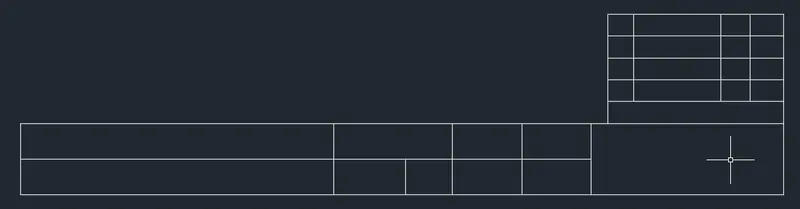
Type L or line in the command box and press enter
Draw the table as per the given figure
STEP 5 :
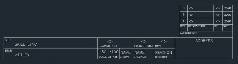
Type DTEXT in the command box and press enter
Add the text where ever required
STEP 6 :
Type B or block in the command box and press enter
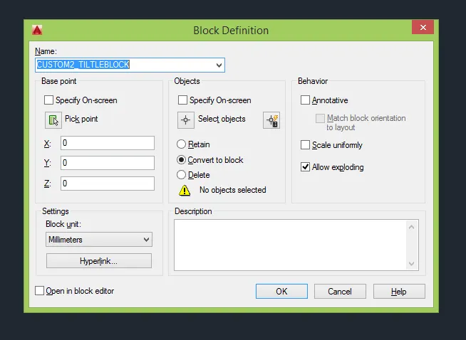
Give the name as CUSTOM2_TITLEBLOCK and pick the point from the AutoCAD screen and press enter and select the object from the screen and press enter
Block is been created
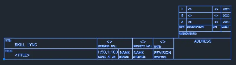
RESULT :
The given Template is drawn using necessary tools from AutoCAD
Q2
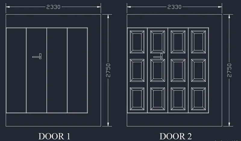
AIM : To Create the door type warehouse as shown in Figures.
PROCEDURE
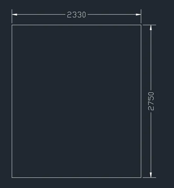
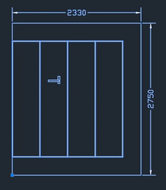
STEP 1:
Type line or L in the command box and press enter
Draw the outer line as given in the figure
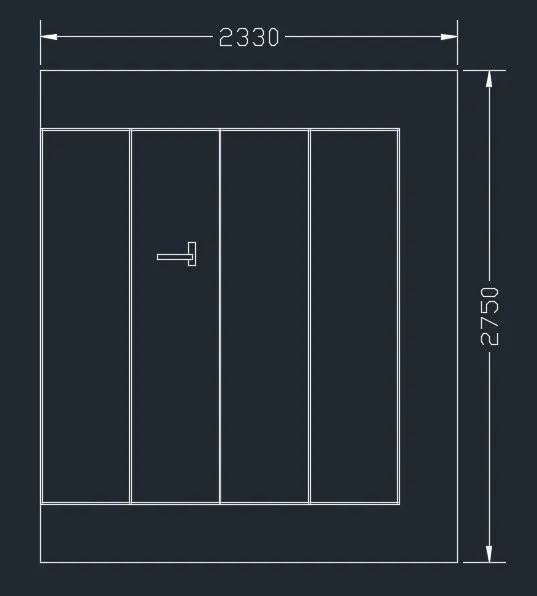
STEP 2:
Type line or L in the command box and press enter
Draw the door as per the given figure
STEP 3 :
Type B or block in the command box and press enter
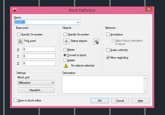
Give the name as DOOR 1 and pick the point from the AutoCAD screen and press enter and select the object from the screen and press enter
Block is been created
STEP 2:
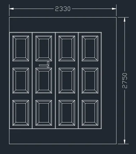
Type line or L in the command box and press enter
Draw the outer line as given in the figure
STEP 2:
Type line or L in the command box and press enter
Draw the door as per the given figure
STEP 3 :
Type B or block in the command box and press enter
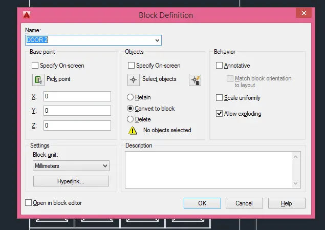
Give the name as DOOR 2 and pick the point from the AutoCAD screen and press enter and select the object from the screen and press enter
Block is been created
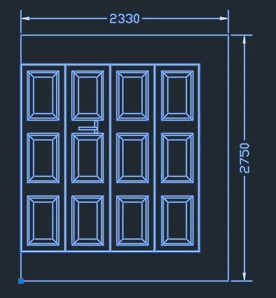
RESULT :
The given door is drawn using necessary tools from AutoCAD
Q3
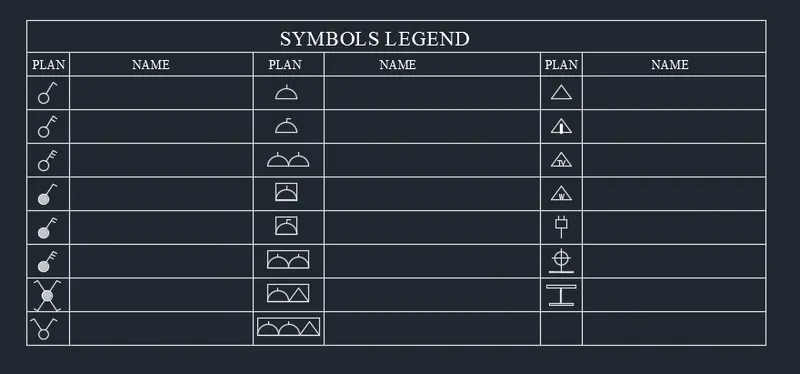
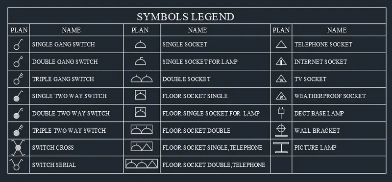
AIM : To Create each symbol as a block with the name given in the legend. After creating the blocks arrange them in the legend as shown in the Figure.
PROCEDURE
STEP 1 :
By using necessary tools draw the symbols and make them Blocks by naming them with there corresponding names

STEP 2 :
Type L or line in the command box and press enter
Draw the table as per the given figure

STEP 3 :
Go to insert and insert the blocks by using the names of the given blocks in the table.
STEP 4 :
Go to insert, select the field option and select the named object and select the name the block which needsto be placed next to the block.
RESULT :
The given table is drawn using necessary tools from AutoCAD
Q4
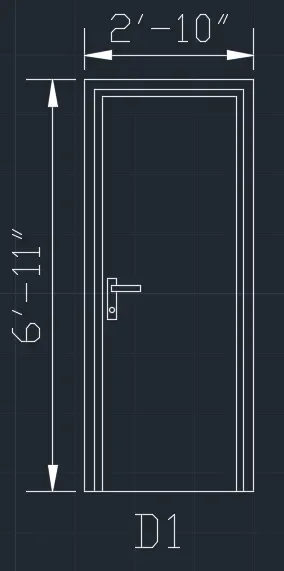
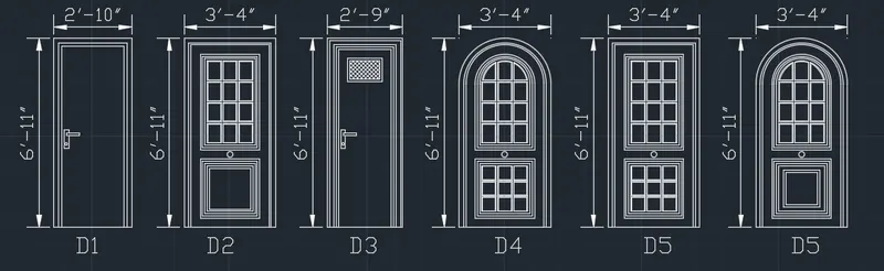
AIM : To create the door type for residential building as a block. Save the name of the blocks as type. Use given dimensions or assume dimensions as per industry standards.
PROCEDURE
STEP 1 :
Type L or line in the command box and press enter
Draw the door D1 by using the line tool, offset tool and trim tool
STEP 2 :
Type B or block in the command box and press enter
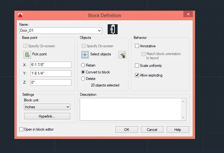
Give the name as Door_D1 and pick the point from the AutoCAD screen and press enter and select the object from the screen and press enter
Block is been created
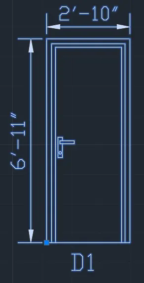
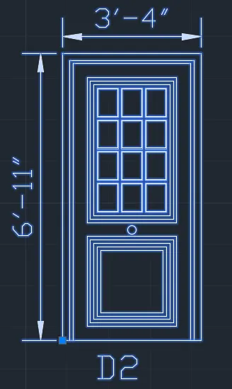
STEP 3 :
Type L or line in the command box and press enter
Draw the door D2 by using the line tool, offset tool and trim tool
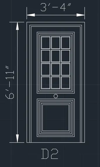
STEP 4 :
Type B or block in the command box and press enter
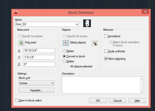
Give the name as Door_D2 and pick the point from the AutoCAD screen and press enter and select the object from the screen and press enter
Block is been created
STEP 5 :
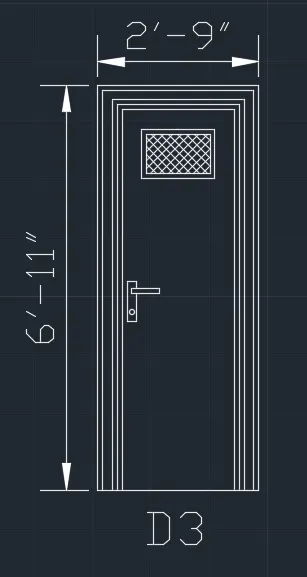
Type L or line in the command box and press enter
Draw the door D3 by using the line tool, offset tool and trim tool
STEP 6 :
Type B or block in the command box and press enter
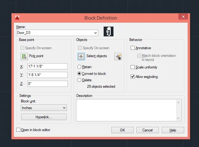
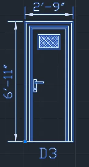
Give the name as Door_D3 and pick the point from the AutoCAD screen and press enter and select the object from the screen and press enter
Block is been created
STEP 7 :
Type L or line in the command box and press enter
Draw the door D4 by using the line tool, offset tool and trim tool
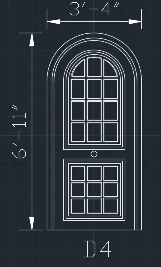
STEP 8 :
Type B or block in the command box and press enter
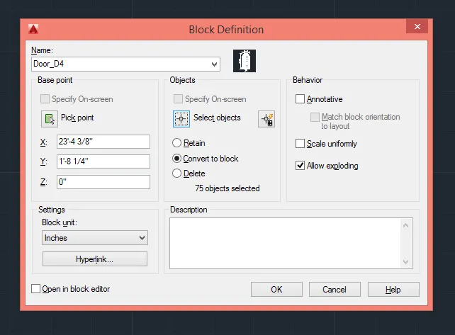
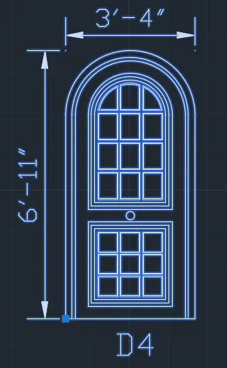
Give the name as Door_D4 and pick the point from the AutoCAD screen and press enter and select the object from the screen and press enter
Block is been created
STEP 9 :
Type L or line in the command box and press enter
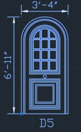
Draw the door D5 by using the line tool, offset tool and trim tool
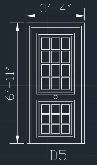
STEP 10 :
Type B or block in the command box and press enter
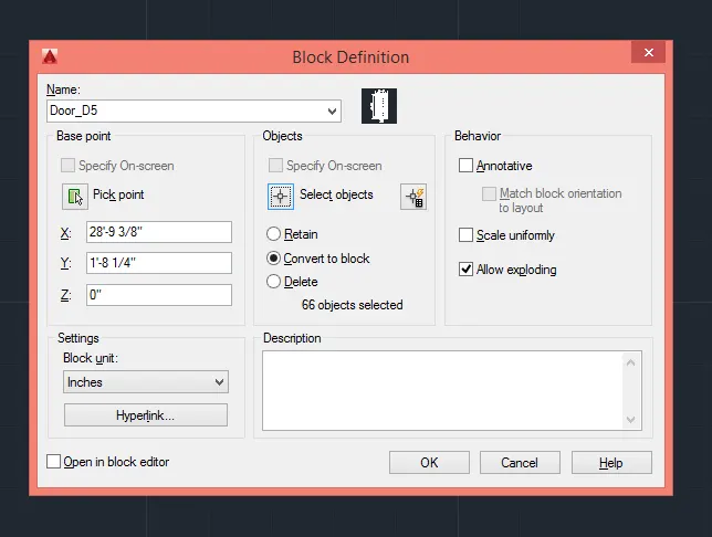
Give the name as Door_D5 and pick the point from the AutoCAD screen and press enter and select the object from the screen and press enter
Block is been created
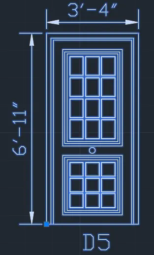
STEP 11 :
Type L or line in the command box and press enter
Draw the door D6 by using the line tool, offset tool and trim tool
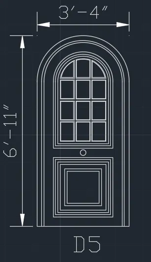
STEP 12 :
Type B or block in the command box and press enter
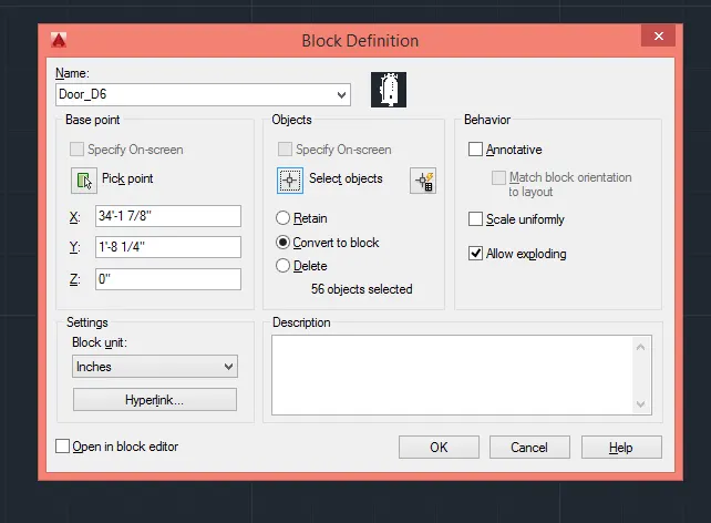
Give the name as Door_D6 and pick the point from the AutoCAD screen and press enter and select the object from the screen and press enter
Block is been created
RESULT :
The given doors is drawn using necessary tools from AutoCAD
Q5
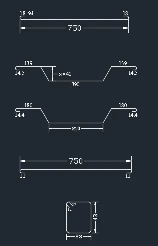
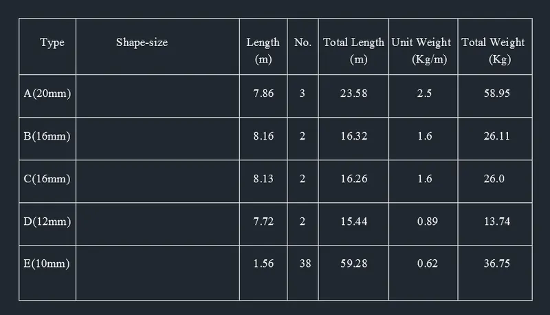
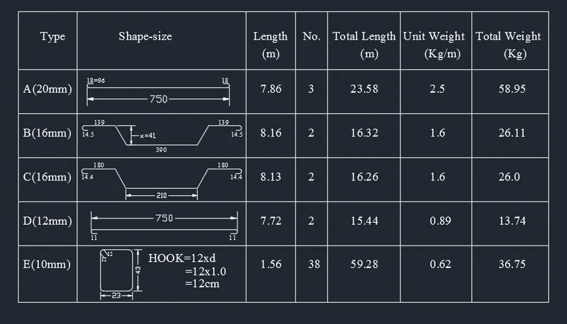
AIM : To Create each shape as a block as shown in the Figure. Save the block and insert them on the table as shown in the Figure.
PROCEDURE
STEP 1 :
By using necessary tools draw the symbols and make them Blocks by naming them with there corresponding names
STEP 2 :
Type L or line in the command box and press enter
Draw the table as per the given figure

STEP 3 :
By using Dtext command add the text where ever it is necessary
STEP 4 :
Go to insert and insert the blocks by using the names of the given blocks in the table.
RESULT :
The given Table is drawn using necessary tools from AutoCAD