Creating Bar Bending schedule, Different Door types, and Creation of standard drawing templates using AutoCad
Name: Allan Bryan Jayson Cruz
Course: Master’s Certification Program in High-Rise Building Design & Analysis
Date: November 13, 2021
Challenge 8 _Creating Bar Bending schedule, Different Door types, and Creation of standard drawing templates using AutoCAD
********************************************************
1. Aim & Introduction
***************
Aim
This challenge aims to provide a deeper understanding to the student about using blocks in the AutoCAD software. By utilizing these commands, the student will be able to create architectural sketches that can be stored within the computer. This challenge aims to let the student create construction details while utilizing the different AutoCAD commands such as blocks and attributes. It also aims to help the student understand the importance of blocks in the AutoCAD software.
Introduction
The AutoCAD software provides different tools. The tools used in this challenge is as described below:
Line - creates line object.
Polyline - creates connected line object.
Rectangle - creates rectangle object.
Circle - create circle object.
Trim - Cut unwanted lines or shapes with the provided cutting edges.
Extend - Extend lines to opposite corners.
Move - Move objects to particular locations.
Copy - Copy objects to particular locations.
Rotate - Rotate selected objects to a particular angle with respect to base point.
Array - Copy an object in a set path linearly or polarly.
Join – Joins separated line objects into one object. Line to polyline.
Dimlinear (DLI) - Provides vertical or horizontal linear/straight dimensions.
Dimaligned (DAL) - Provides aligned dimensions.
Dimangular (DAN) – Provides angular dimensions.
Quickdimension (QDIM) – Provides quick dimension of a geometry.
Leader - Creates an arrowhead line.
Layers - Provide identification of line or object groups by their properties.
Units - Open "Drawing Units" window to specify the drawings units.
Dimstyle - Open "Dimension Style Manager" window to modify the dimension properties.
Hatch - Provides hatching pattern in a given object or internal point.
Layer - Open the layer tab which manages the line properties in a drawing.
Block - To create blocks that form multiple objects into one object.
********************************************************
2. Sketch and Procedure
***************
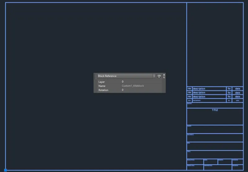
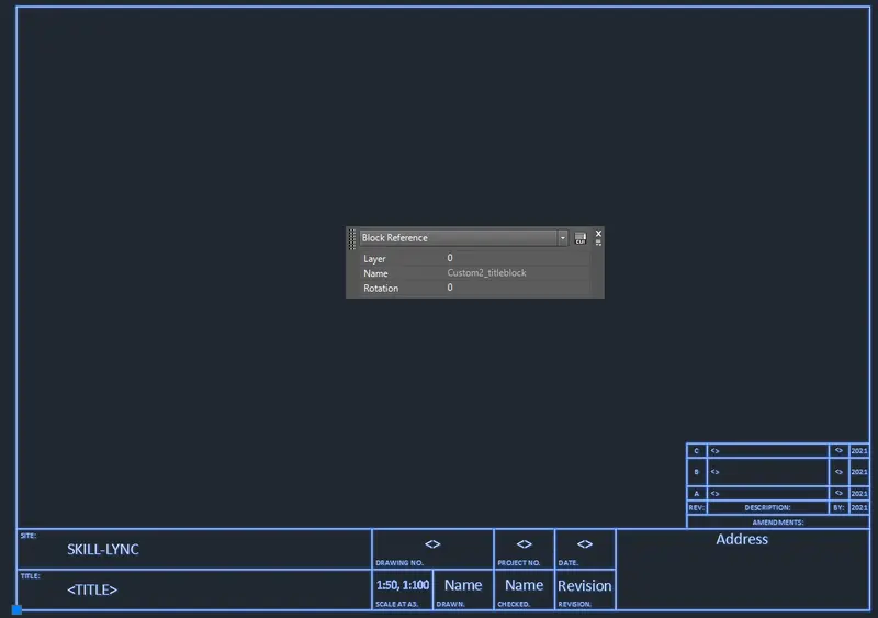
A) Create the templates as shown in Figures. Take the size of the title block as per industry standards or you can assume it as per the size of the paper. Use text and attributes wherever required. After creating the title block you need to save it as a block with names: Custom1_titleblock and Custom2_titleblock, respectively.
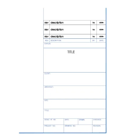
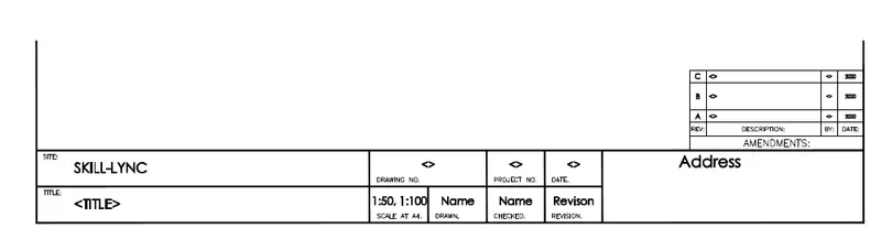
PROCEDURE:
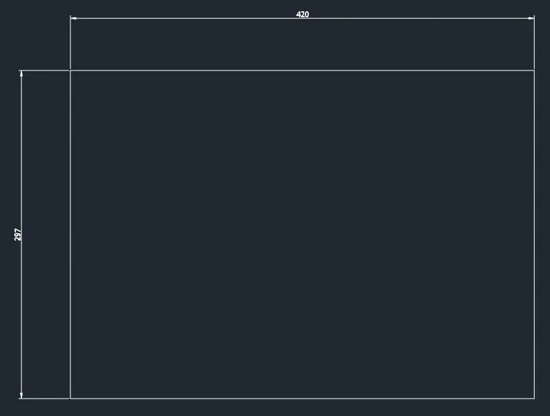
Note: The titleblocks will be made for an A3 size paper (420mm X 297mm)
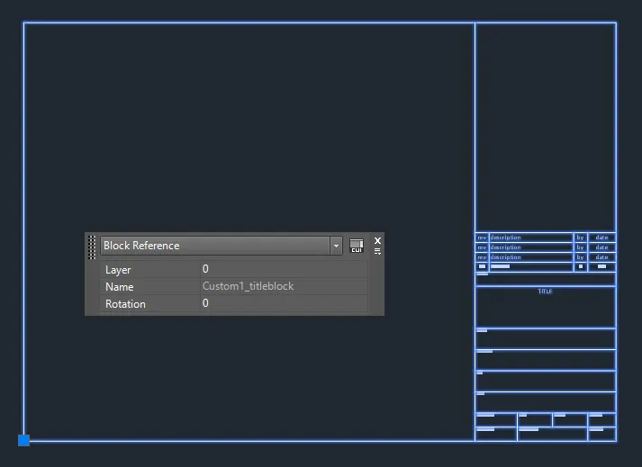
--> Proceed with Custom1_titleblock
- Create the boundary rectangle. 420mm X 279mm.
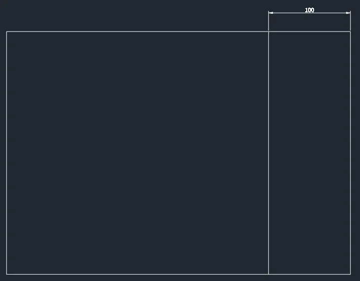
- Create the inside space. 100mm dimension.
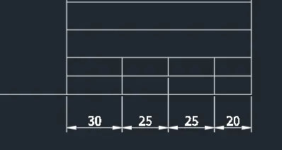
- Add the boundaries at the bottom using line and offset command. You can adjust the dimensions later to the appropriate dimensions depending on the text/space requirement.
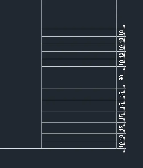
- Start from the bottom to the top.
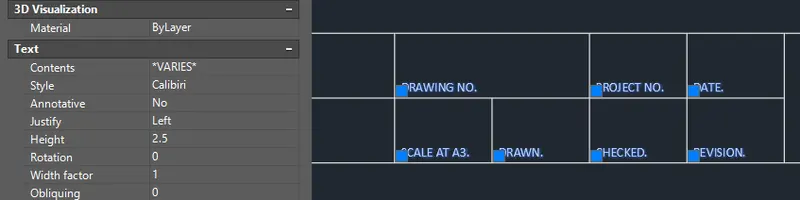
- Add the texts using dtext command. Use text height = 1.5mm
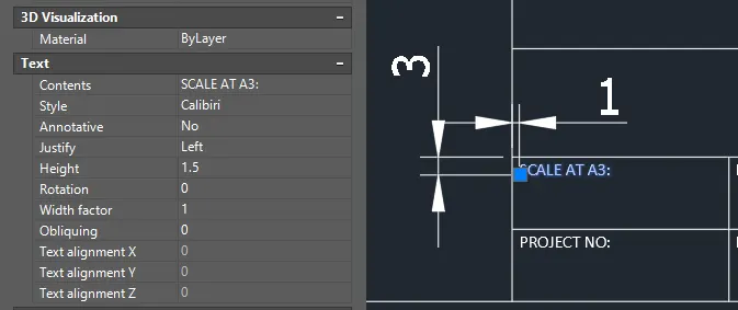
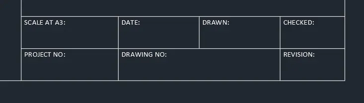
- Copy the texts using the copy tool and double click the text to enter textedit mode. Change it accordingly.
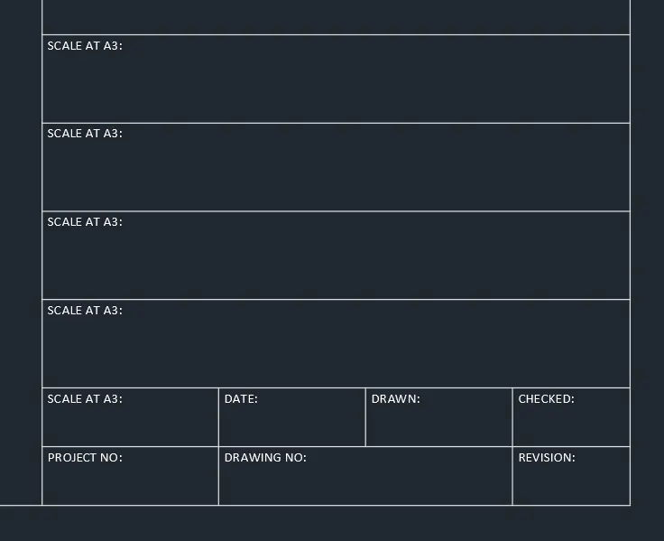
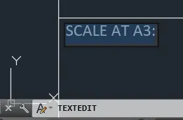
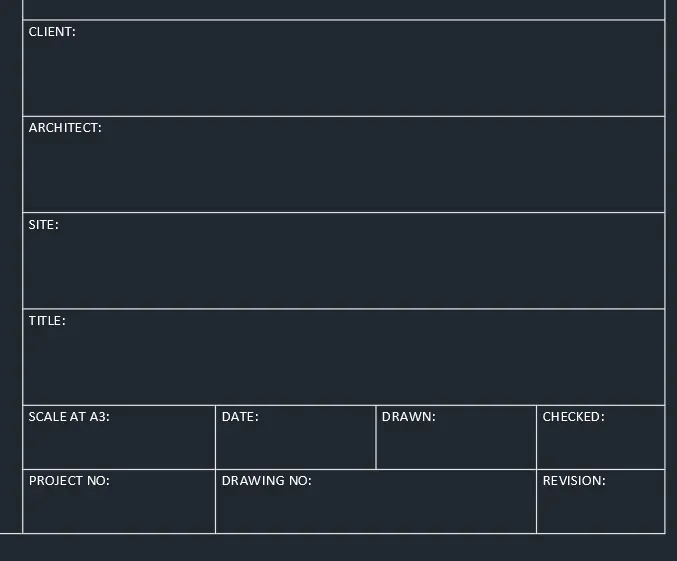
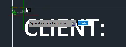
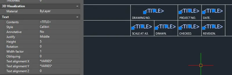
- Copy again for the "TITLE" name. Use scale command to increase the size of the text.
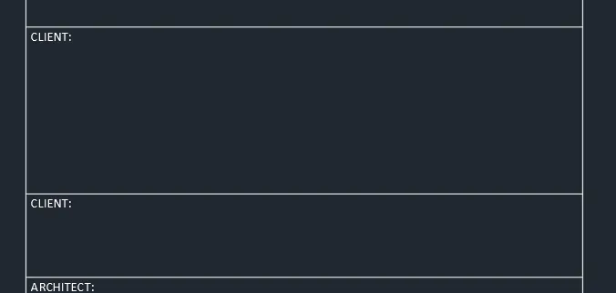
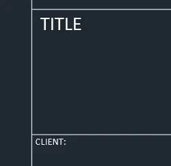
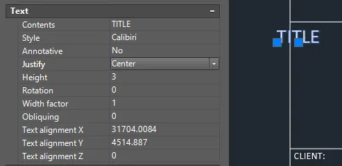
- Change alignement to "Center" and drag the center grip to the center of the line.

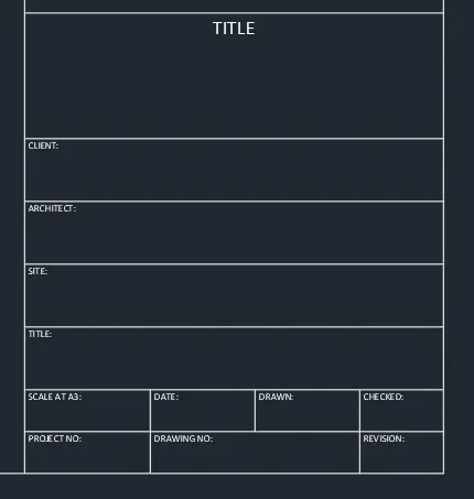
- Now do the same procedures as above to complete the title block.
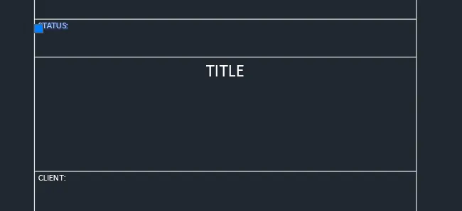
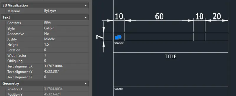
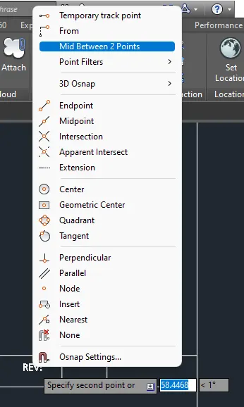
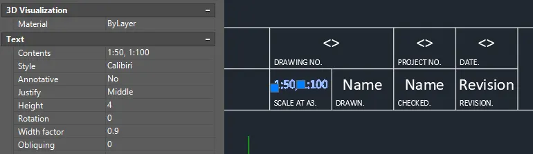
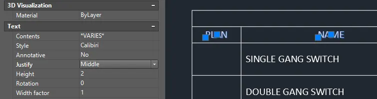
- Use the "Mid between two points option to center the text. Use justify "Middle for these texts for better procedure.


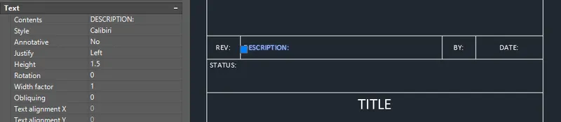
- Copy the created text and scale the text by 2 or change the text height in the properties tab.

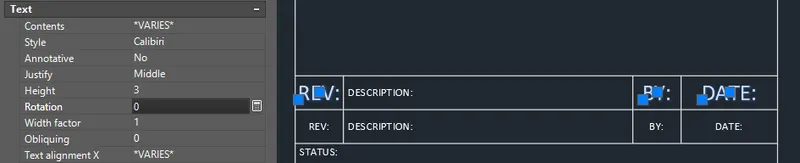
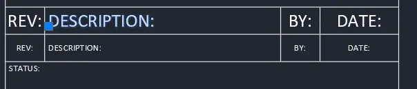
- Double click the texts and copy twice upward to complete.
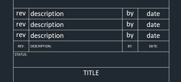
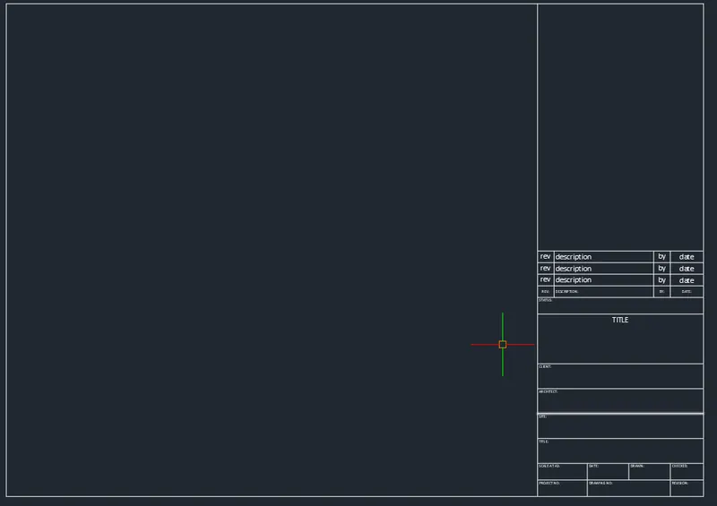
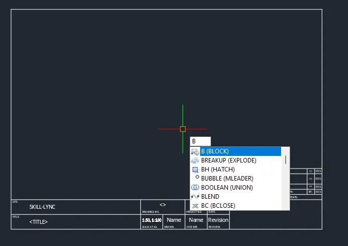
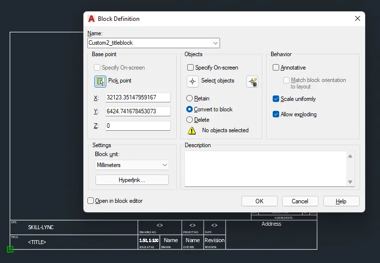
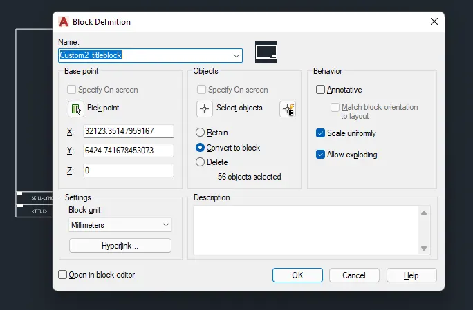
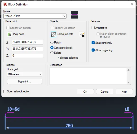
- Make it a block. Open Block Definition Window by typing "b" on the command prompt.
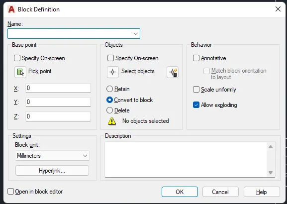
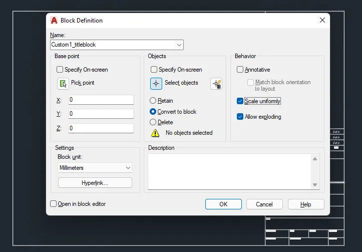
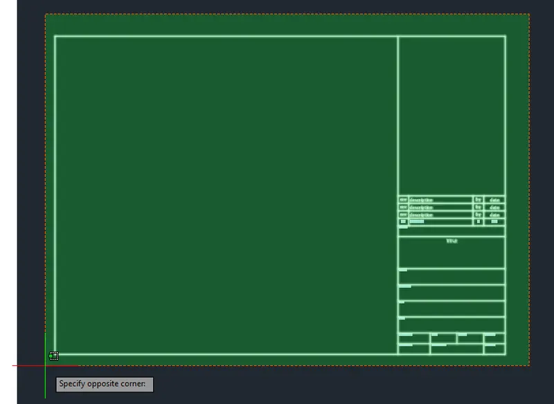
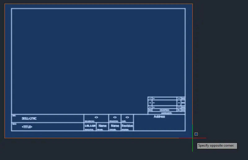
- After selecting the objects, double check the parameters and press OK. Specify the base point to be precise.
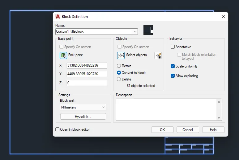
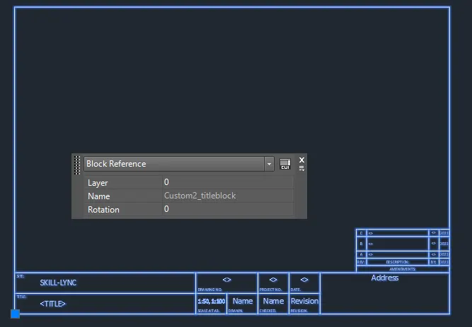
--> Proceed with Custom2_titleblock
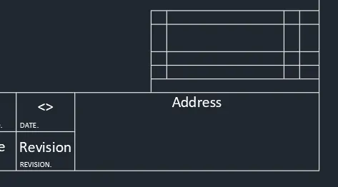
- Do the same procedure as above. Utilize rectangle tool, line tool, offset cool, copy tool and dtext tool to sketch.
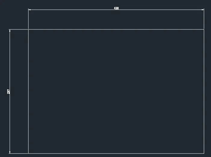
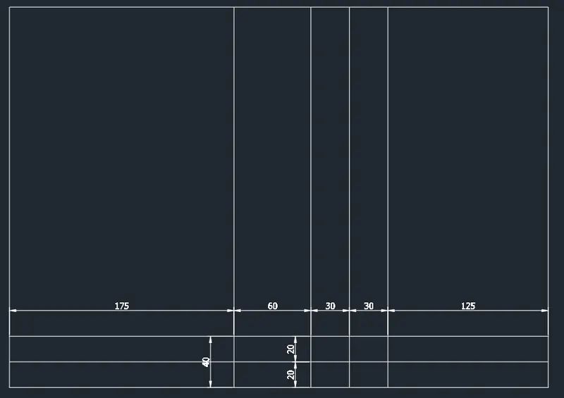
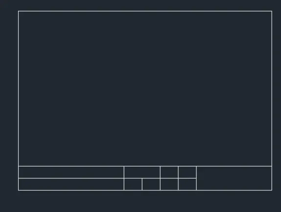
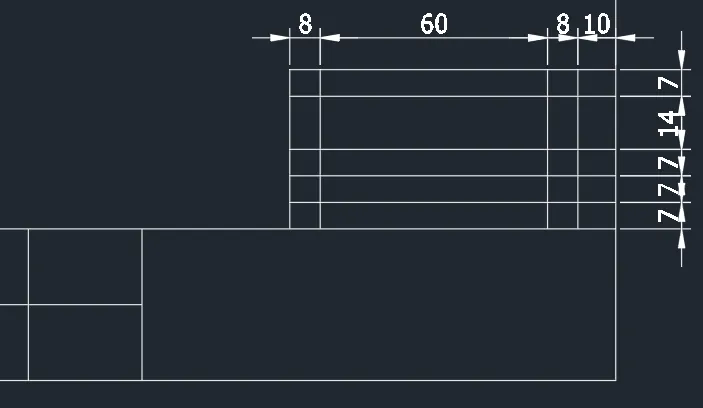
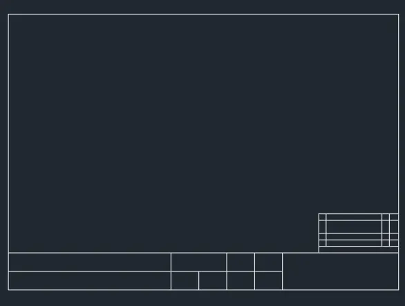
- Add the texts using dtext command and utilize the properties tab, copy tool, scale tool and move tool.
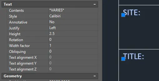

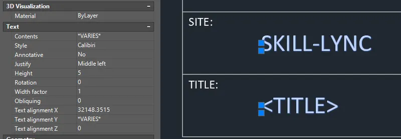
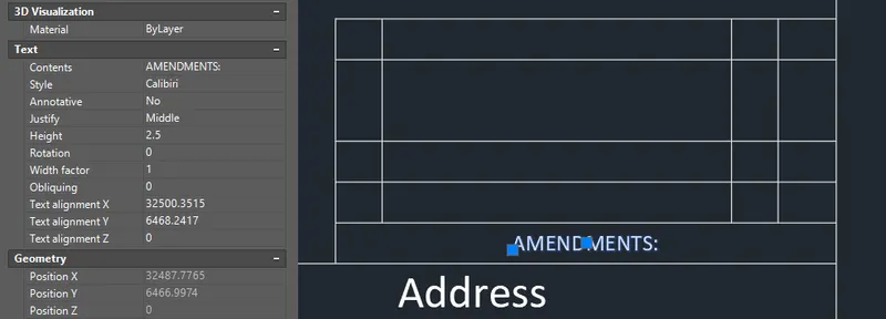
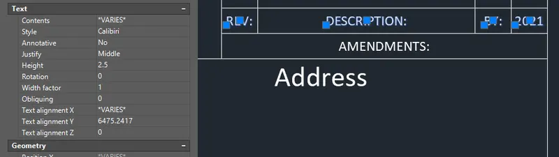
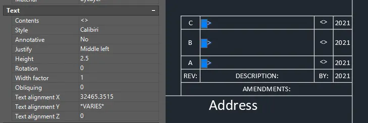
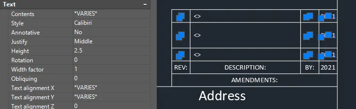
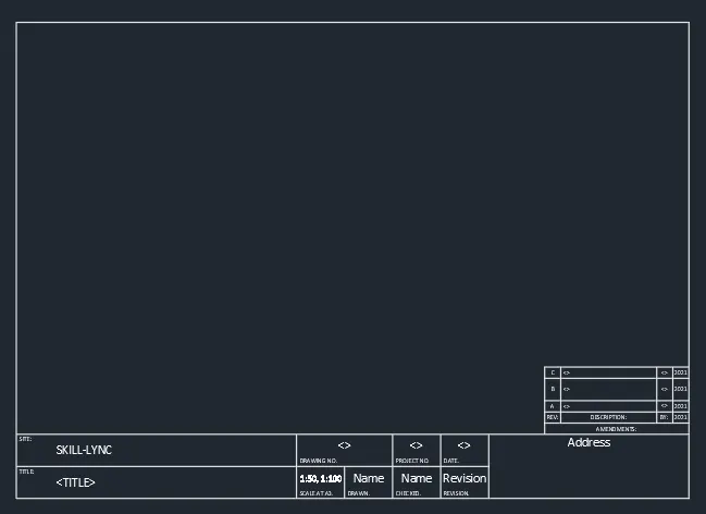
- Make it as a block. Use same procedures as above.
FINAL PRODUCT:
***************
B) Create the doors type for warehouse as shown in the Figure. You need to create each door type as per standard size or given dimensions. Create the blocks of this door type after creating them.
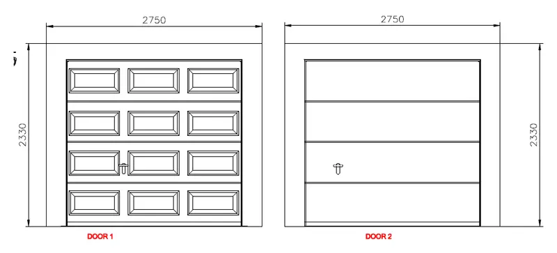
PROCEDURE:
- Create the door boundaries. Use rectangle tool and offset tool to create the door.
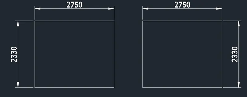
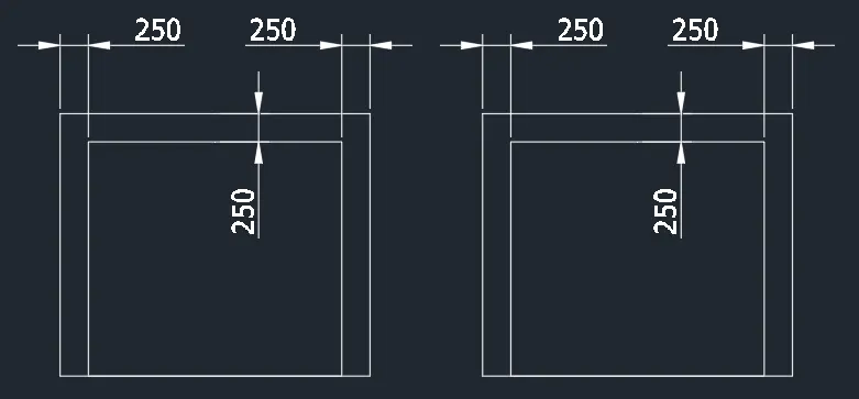
--> Proceed with Door 1
- Explode the lines to utilize it better.
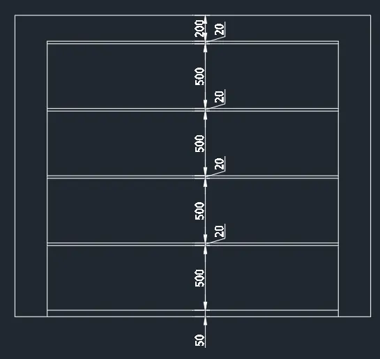
- Now proceed with the vertical lines.
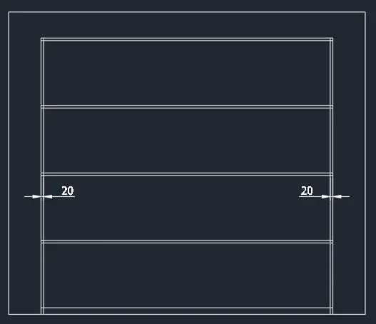
- Create the rectangles per layer.
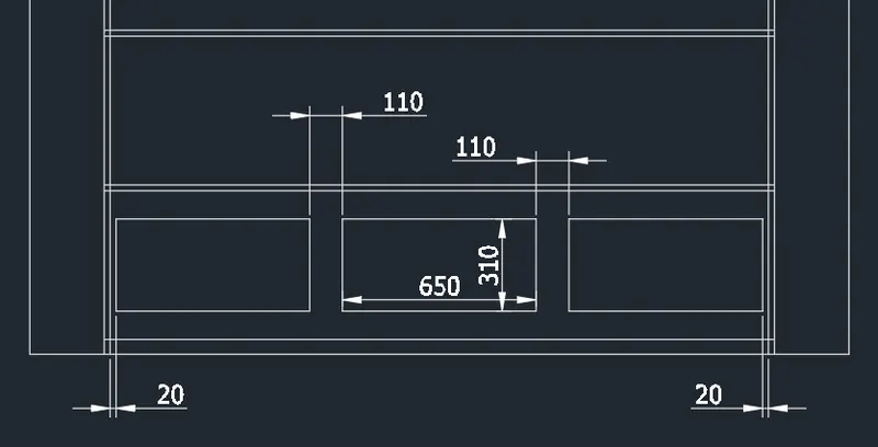
- Create the insides of the rectangle. Use offset and line tool.
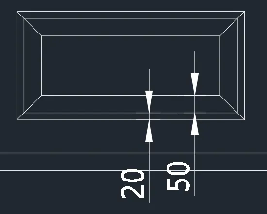
- Copy the inside lines to other rectangles.
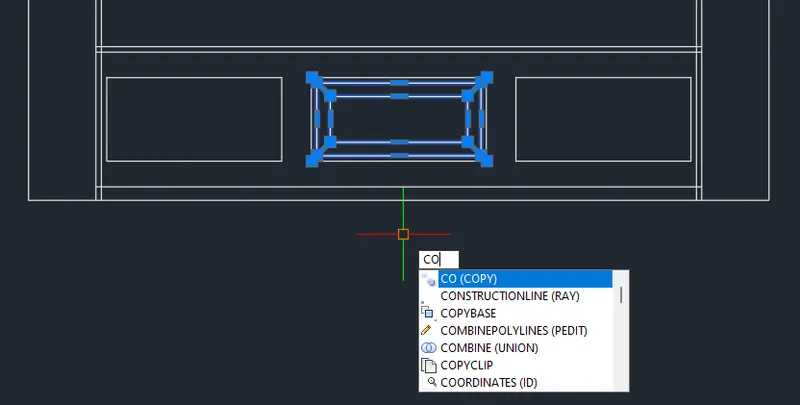
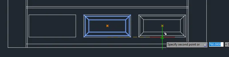
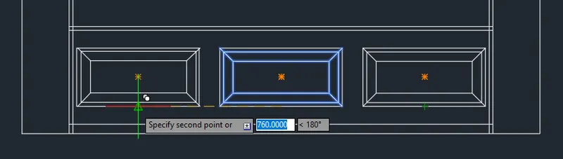
- Copy the three rectangles to the other layers.
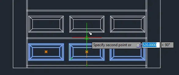
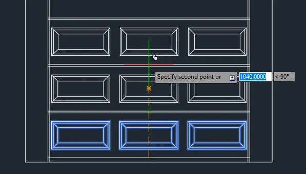
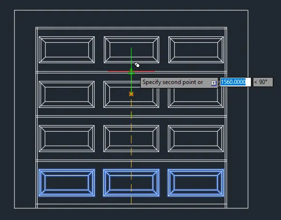
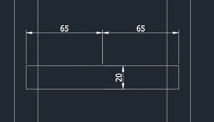
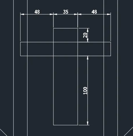
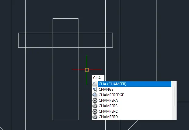
- Add the handle using rectangle and chamfer tool.
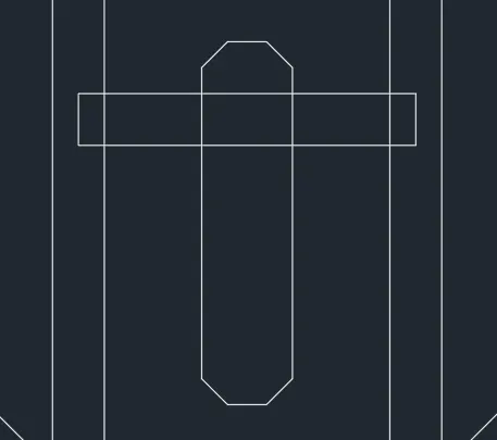
- Trim the unnecessary lines.
- Add the dimensions and text using dimlinear and dtext.
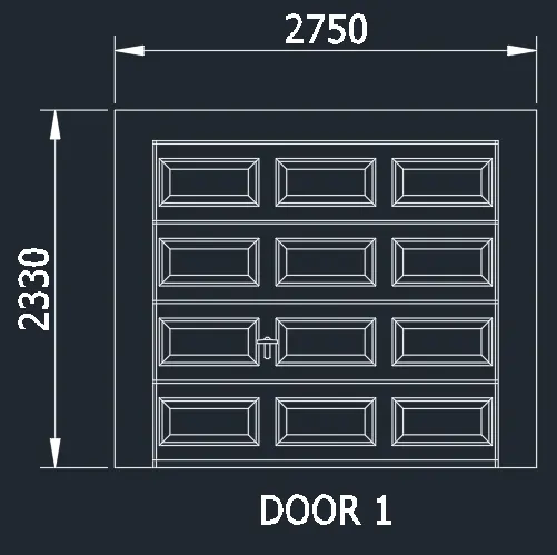
- Make the door into block using the block command.
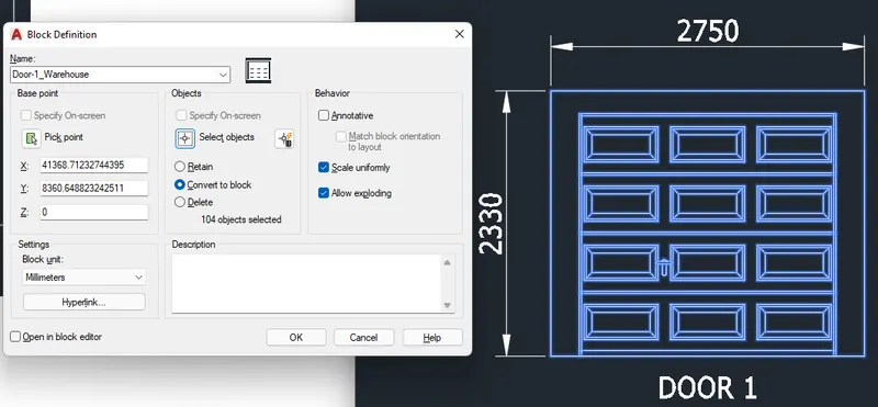
--> Proceed with door 2.
- Copy the door borders and handle to door 2 boundary.
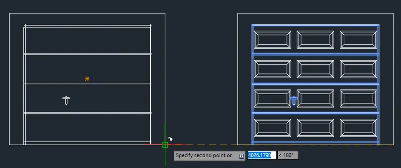
- Add text and dimensions. Then make it as a block to finish.
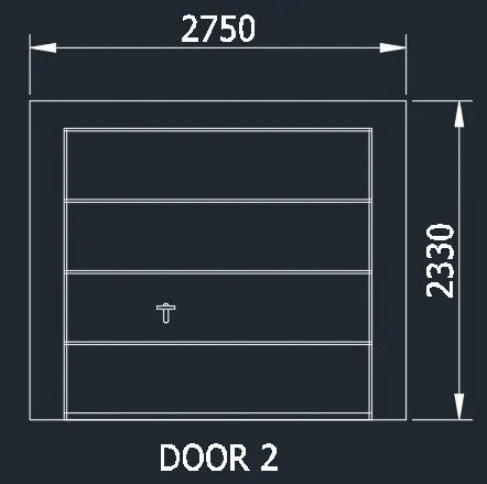
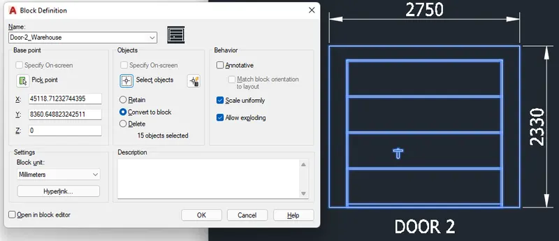
FINAL PRODUCT:
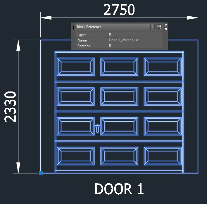
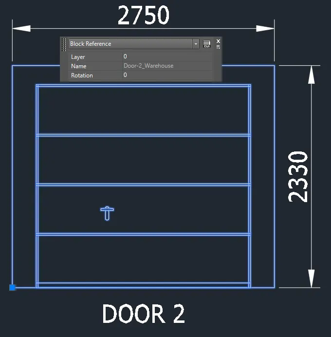
***************
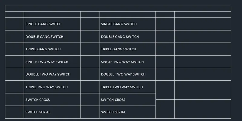
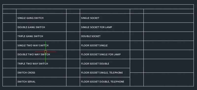
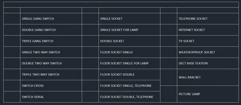
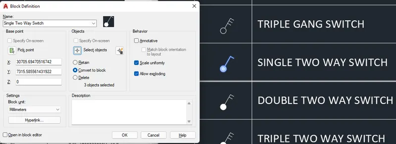
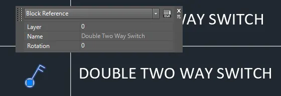
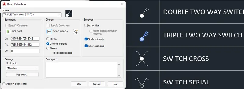
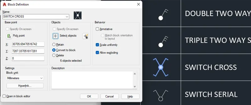
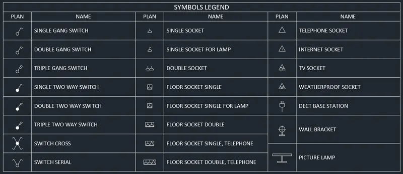
C) Create each symbol as a block with the name given in the legend. After creating the blocks arrange them in the legend as shown in the Figure.
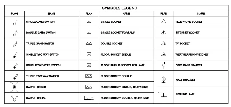
PROCEDURE:
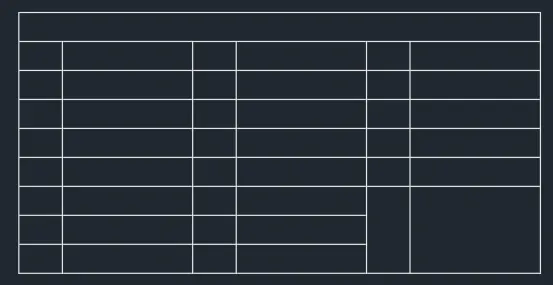
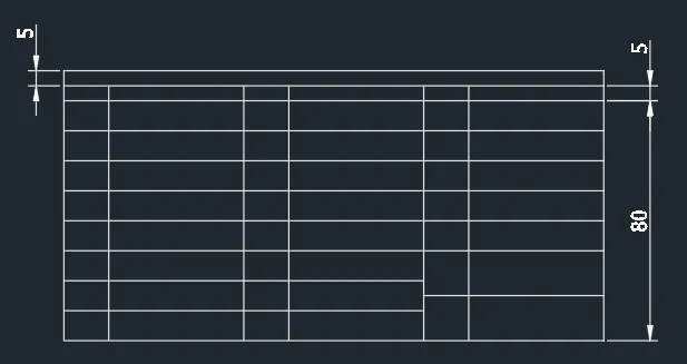
- Create the boundary
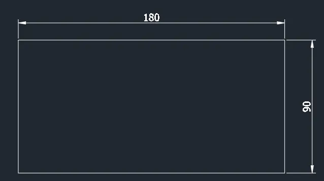
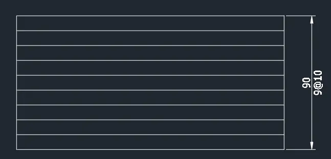
- Create the layers. You can adjust the dimensions later by stretching the lines if the texts does not fit.
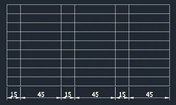
- Trim the unnecessary lines.
- Add the texts using dtext.
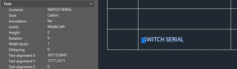
- Copy the text object and double click to edit texts.
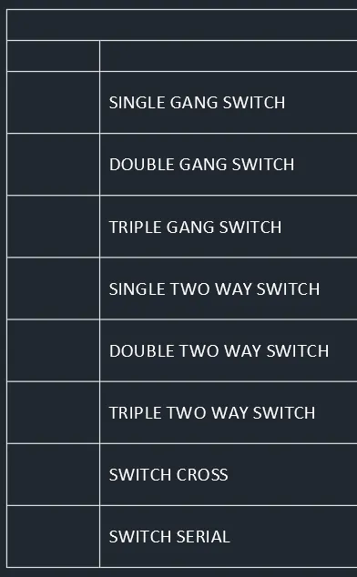
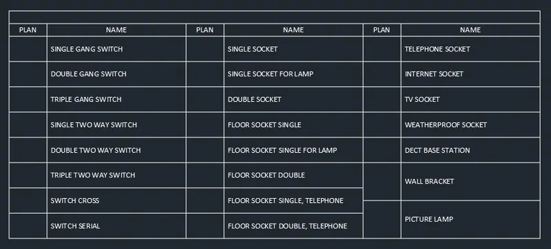
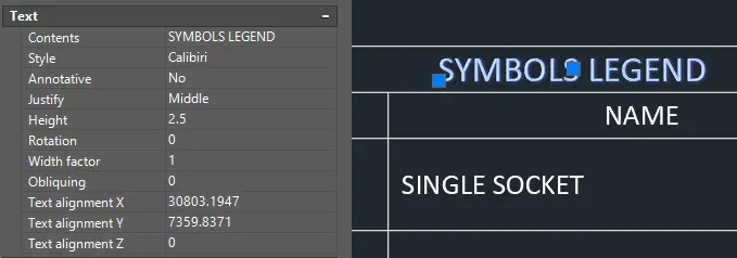
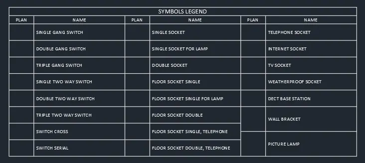
- Proceed with the symbols.
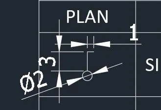
- Rotate the symbol to finish.

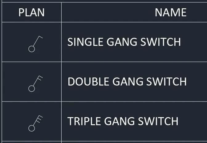
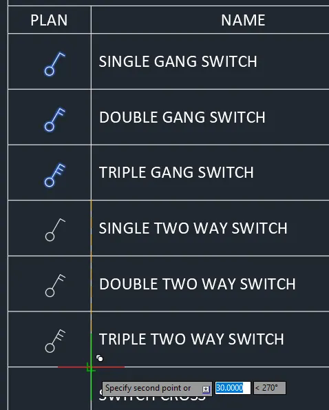
- Add hatches on the copied symbols.
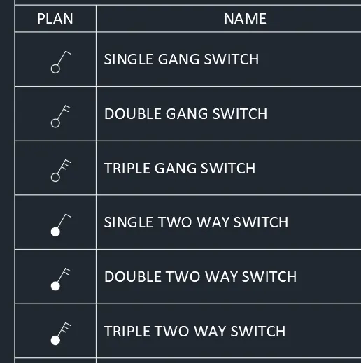
- Copy the symbol again and edit the symbol using mirror command, line command and copy command.
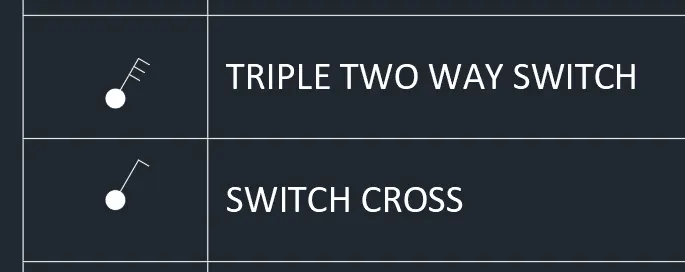
- Use the mirror commands to create the legs.
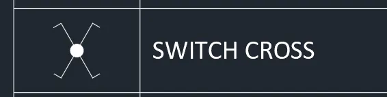
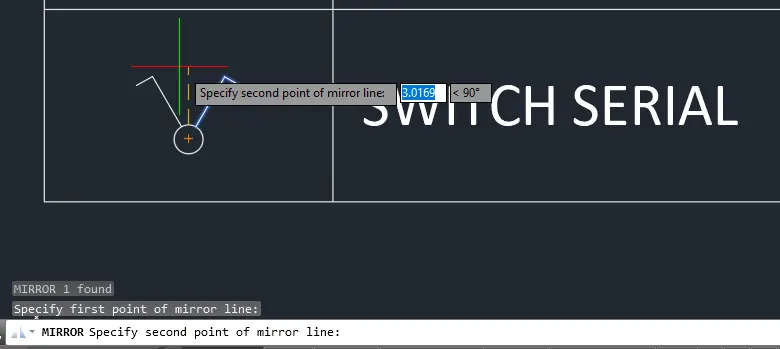
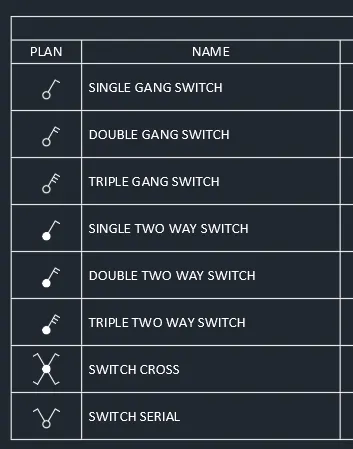
- Proceed with the next column.
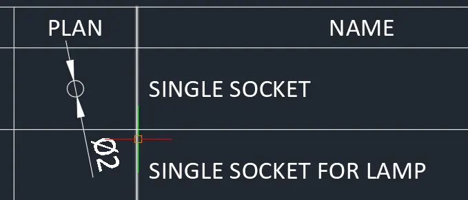
- Add horizontal line in the middle then trim the bottom.
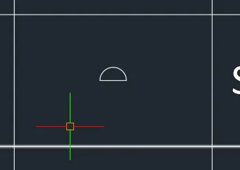
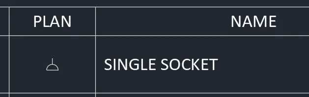
- Copy to the next column and a horizontal line.
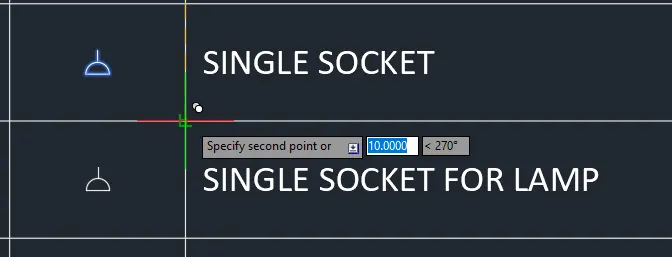
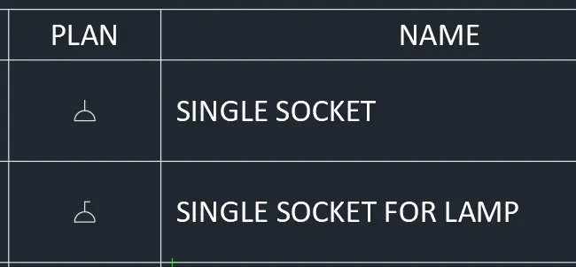
- Copy to the next column and duplicate.
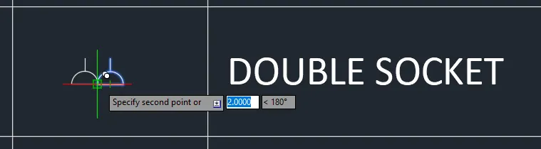
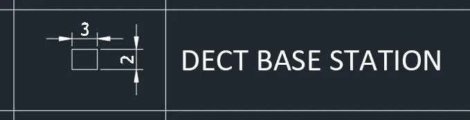
- Add rectangles to the other symbols to create the next symbols.
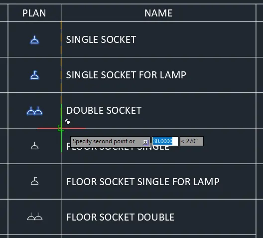
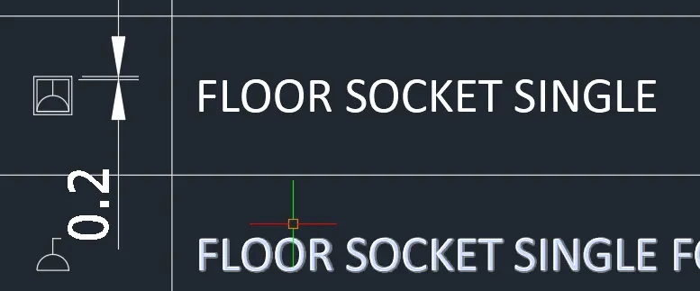
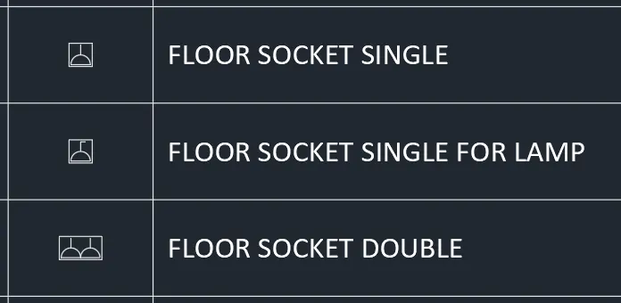
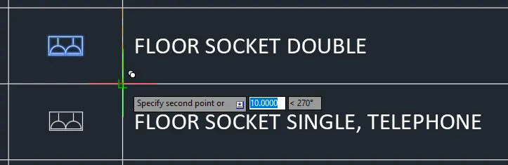
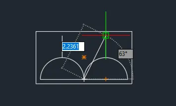
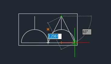
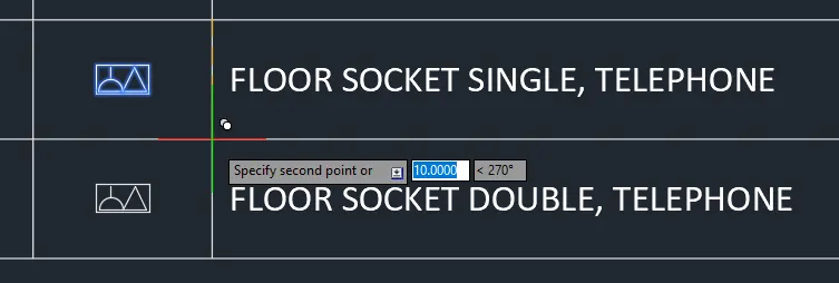
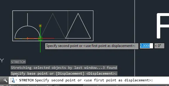
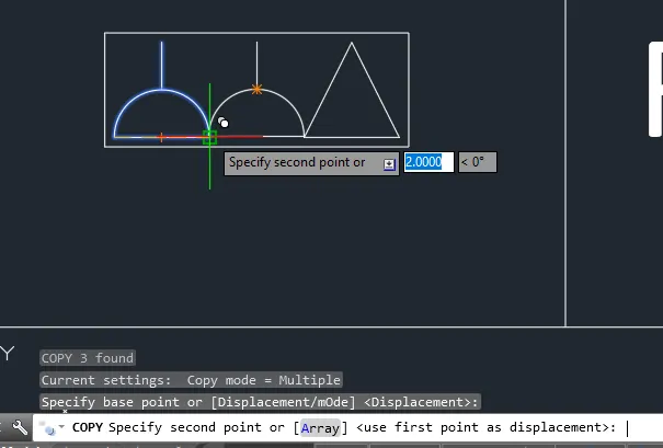

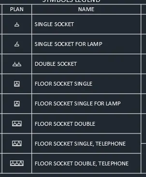
- Move to the next column.
- Create a polygon with 3 sides incribed in a circle with 2unit radius.
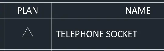
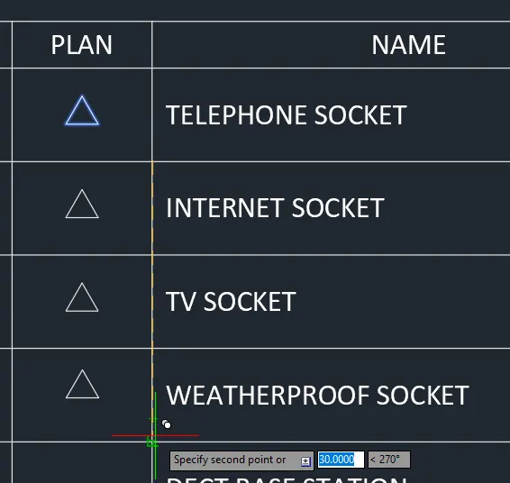
- Add texts inside using dtext command.
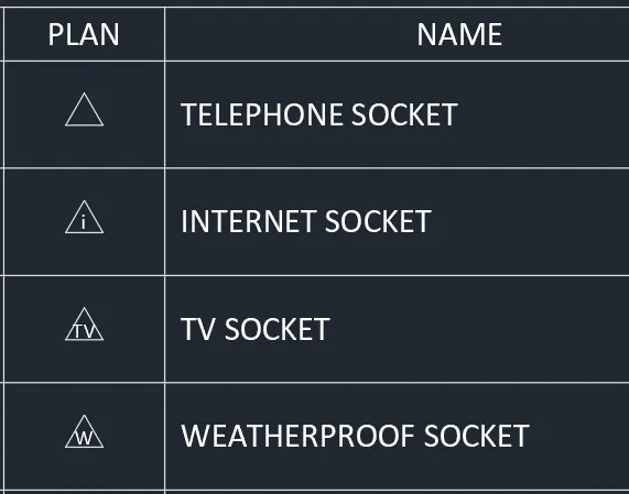
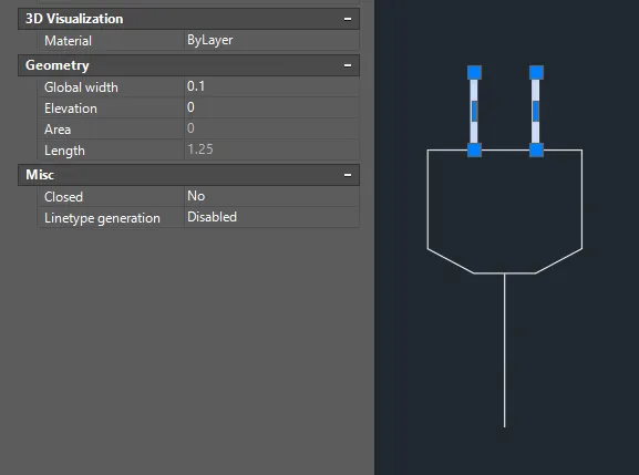
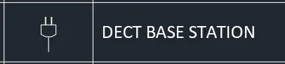
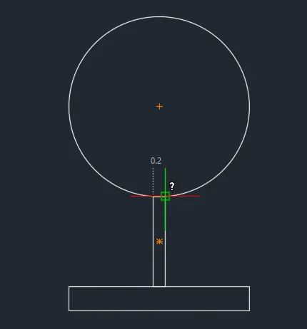
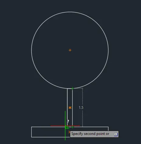
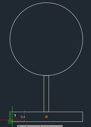
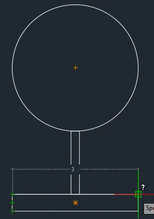
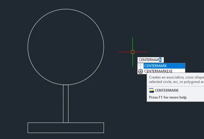
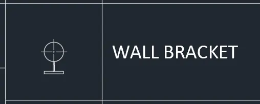
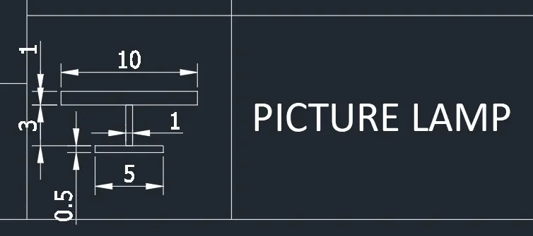
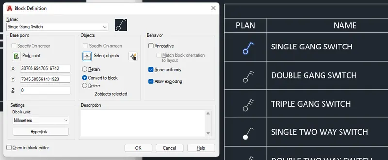
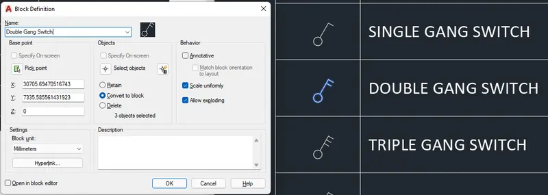
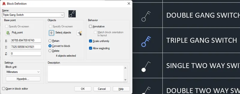
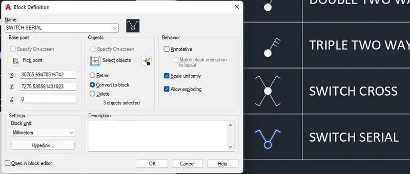
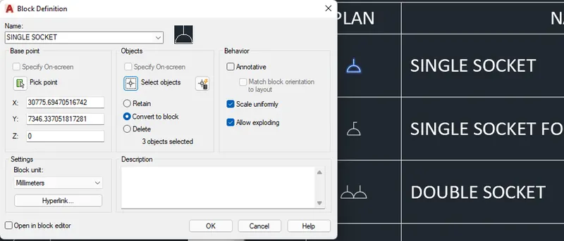
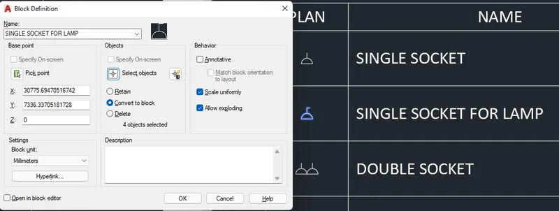
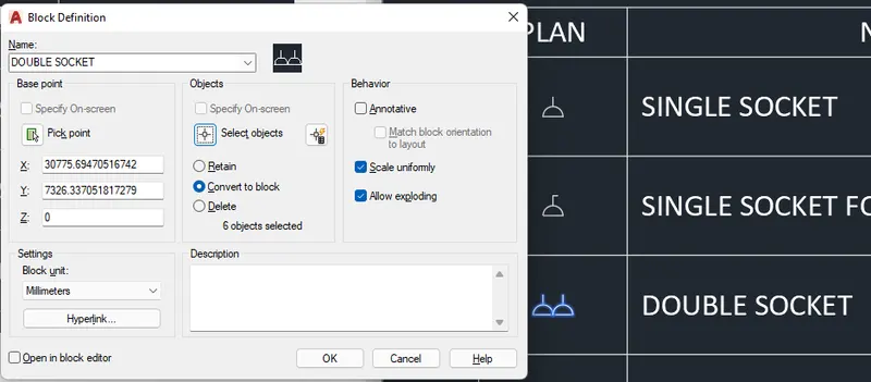
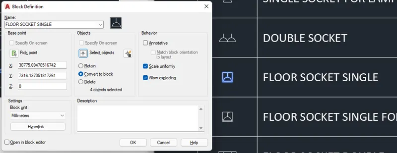
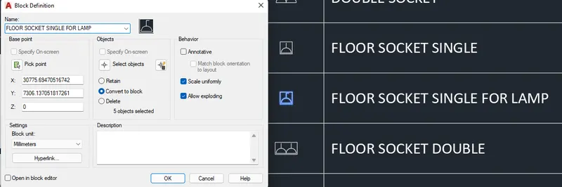
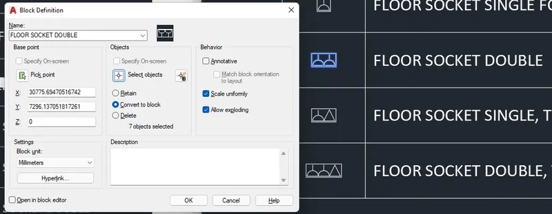
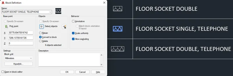
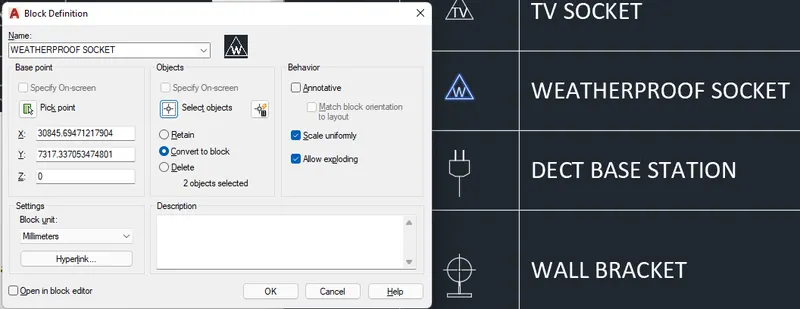
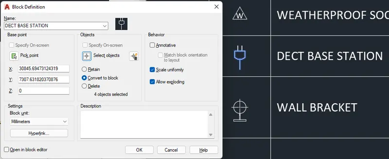
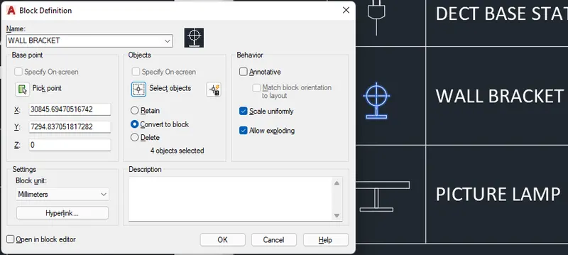
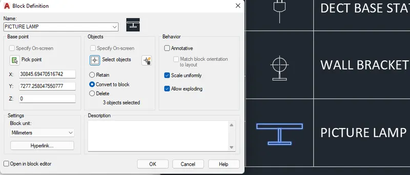
- Make all the symbols as block. Name it with the correct name.
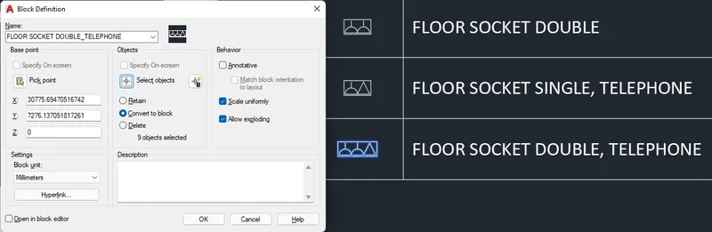
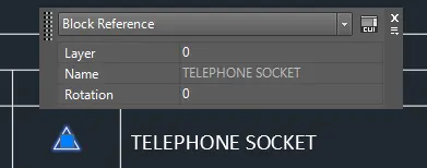
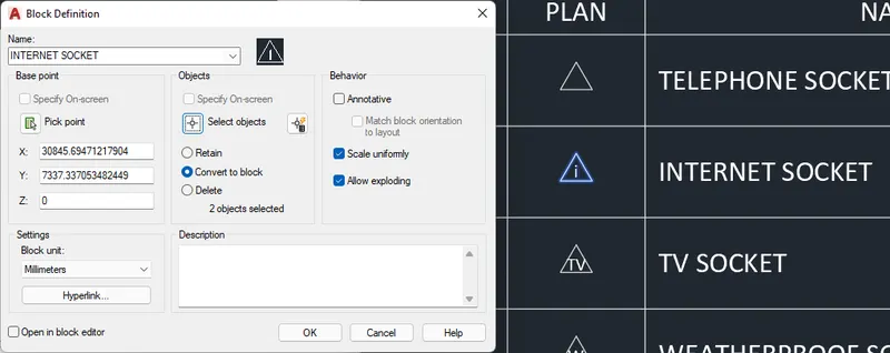
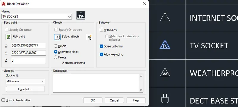
FINAL PRODUCT:
***************
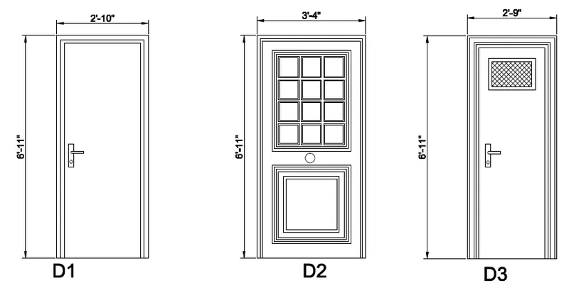
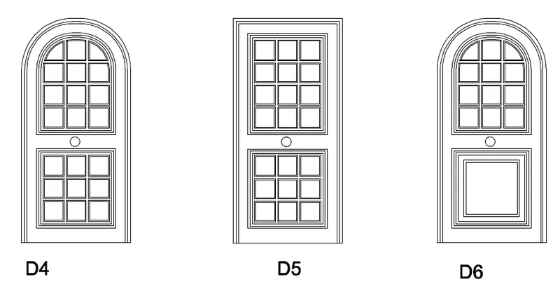
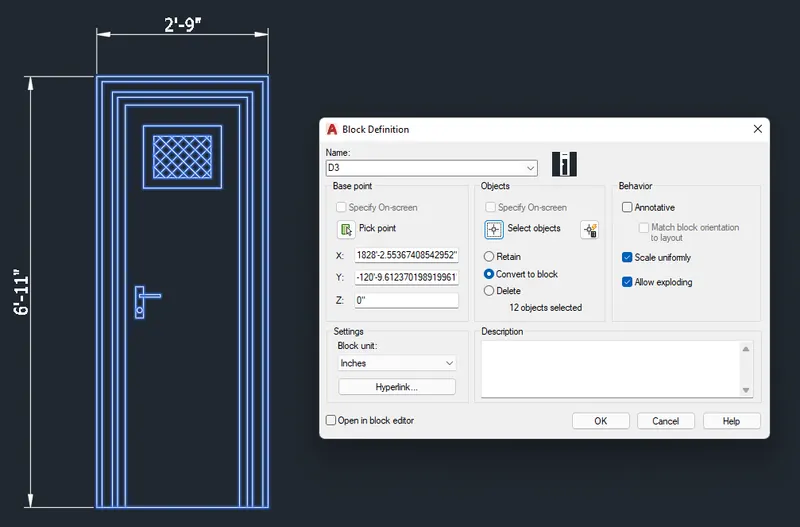
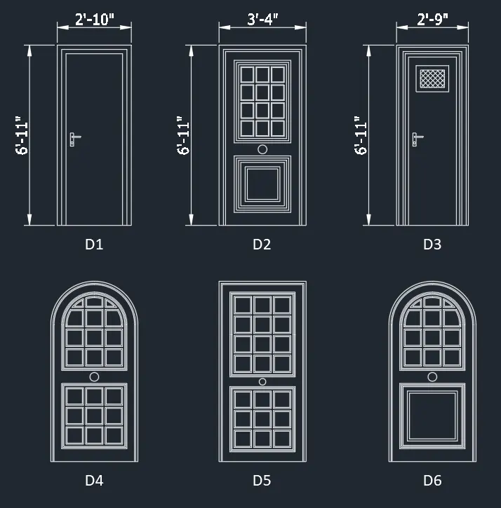
D) Create the door type for residential building as a block. Save the name of the blocks as type. Use given dimensions or assume dimensions as per industry standards.
PROCEDURE:
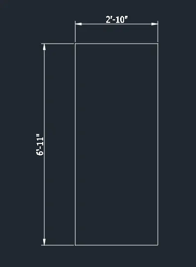
--> Proceed with door 1.
- Use rectangle command.
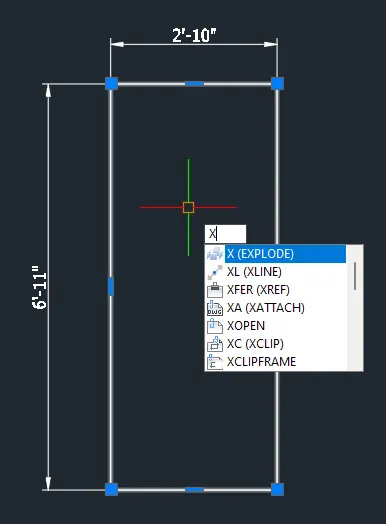
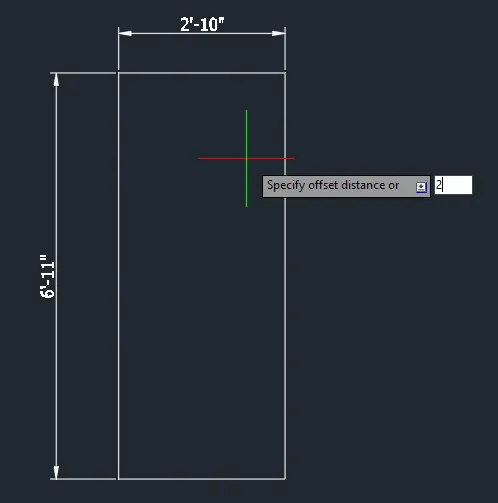
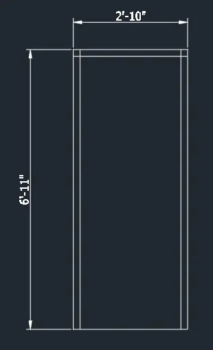
- Trim lines and offset again.
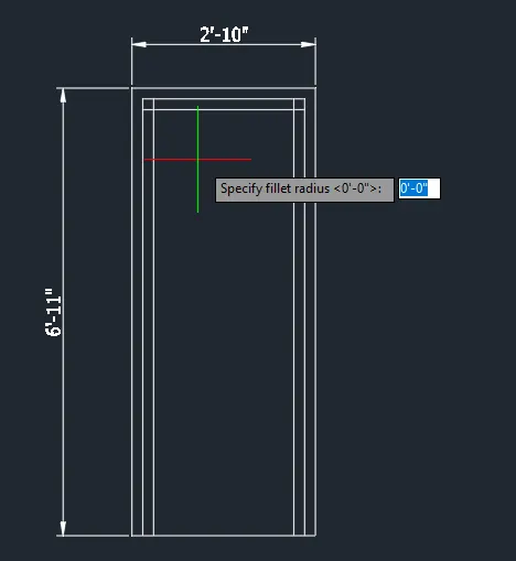
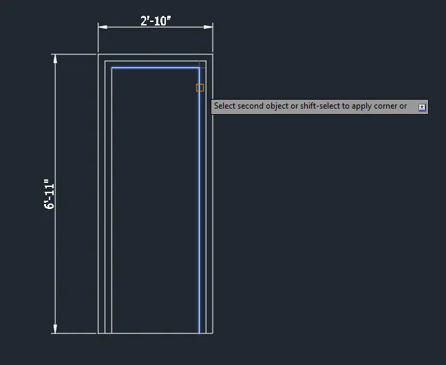
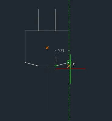
- Draw the door knob.
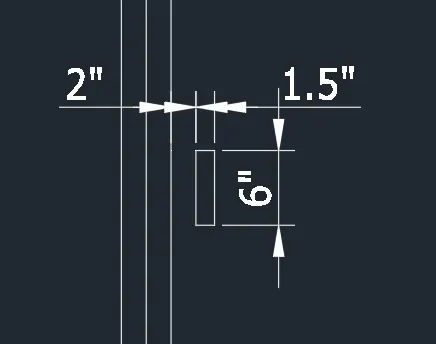
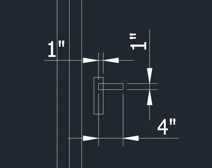

--> Proceed to Door 2.
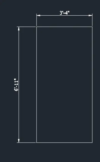
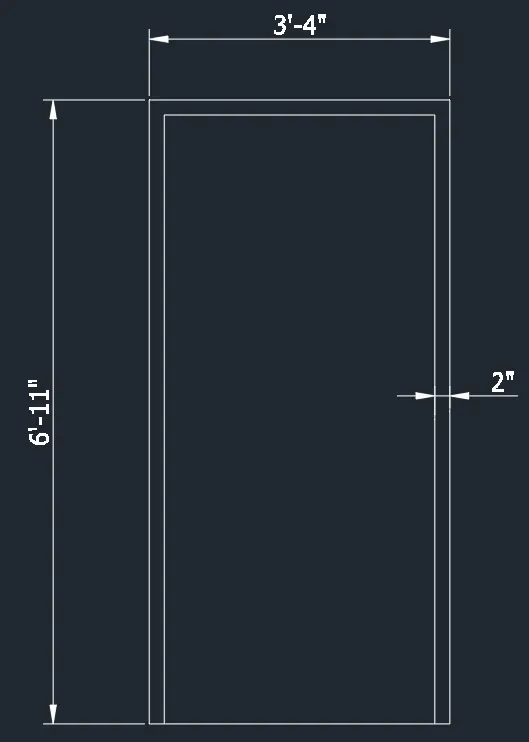
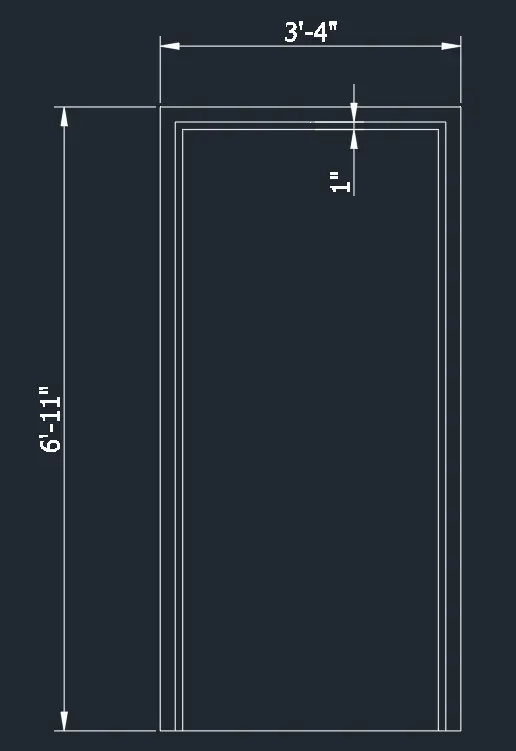
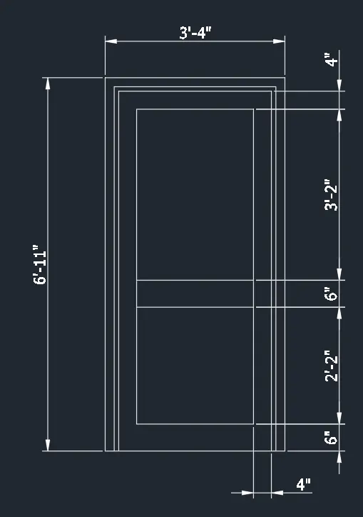
- Join the lines for offset.
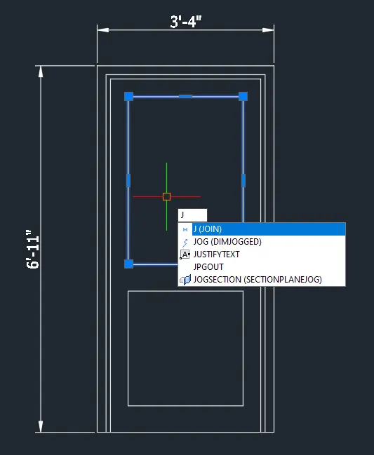
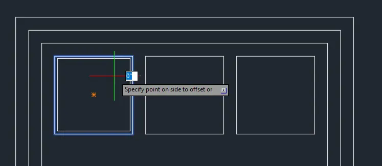
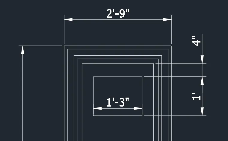
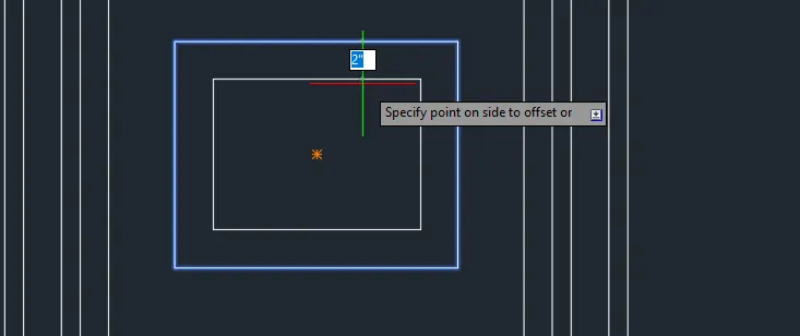
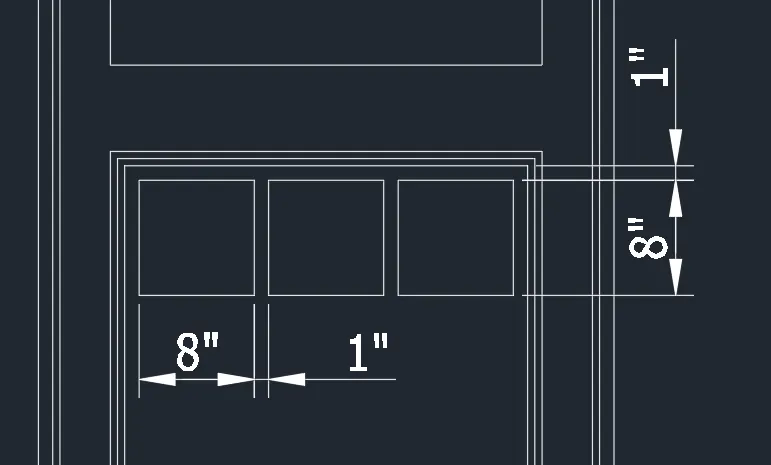
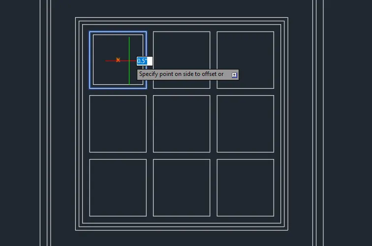
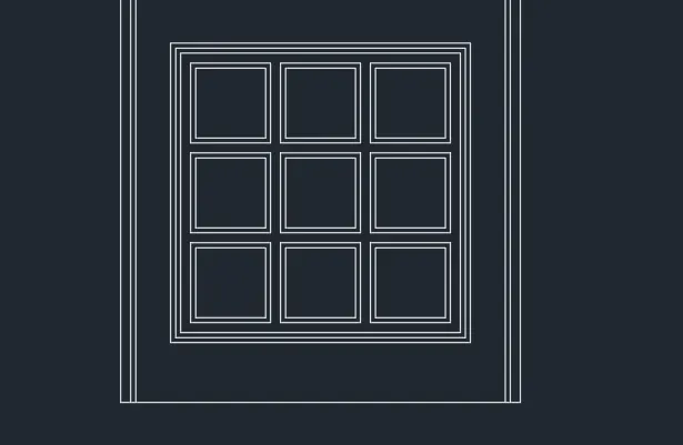
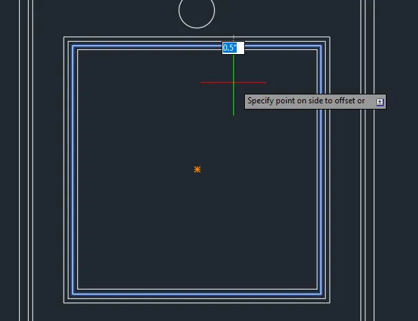
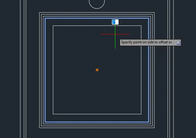
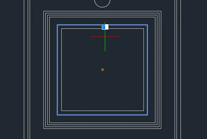
- Offset the lines to create the image. Use multiple for successive offsets.
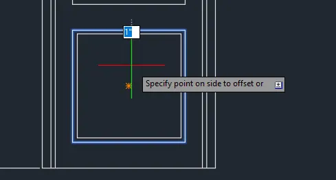
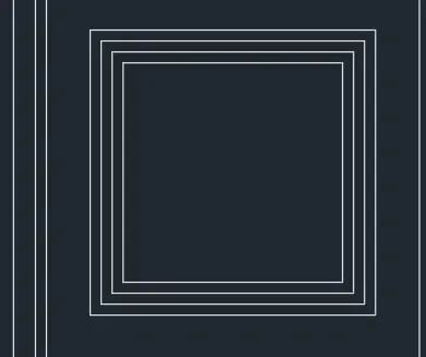
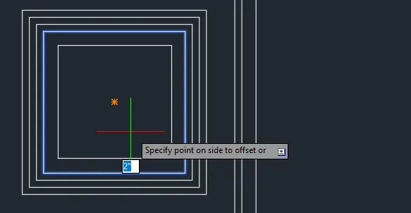
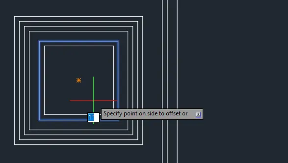
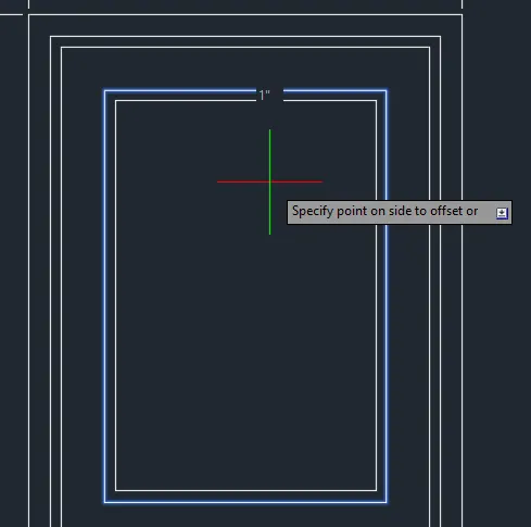
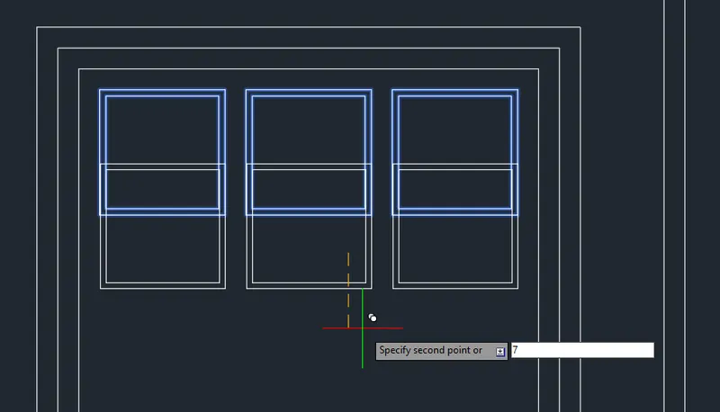
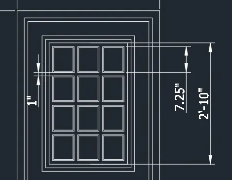
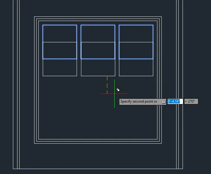
- Create the rectangles per layer. Then copy to duplicate. Adjust the squares if needed.
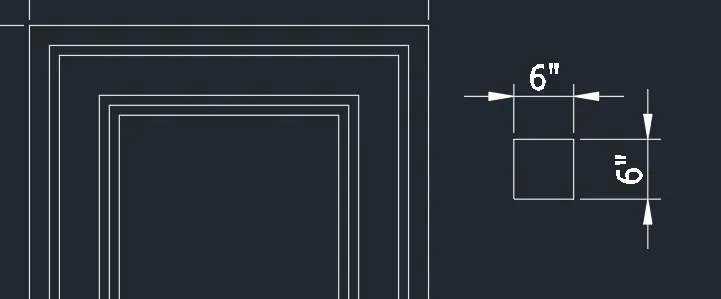
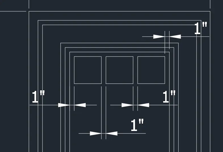
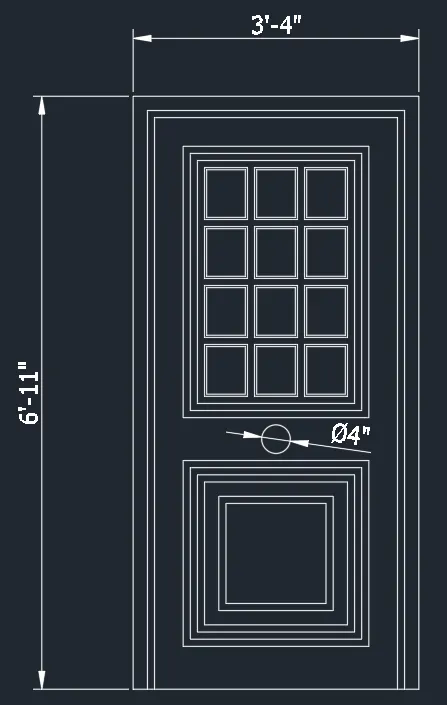
- Add the circle at the middle.
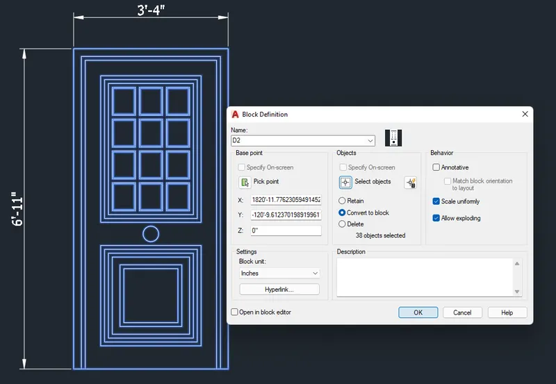
--> Proceed to Door 3.
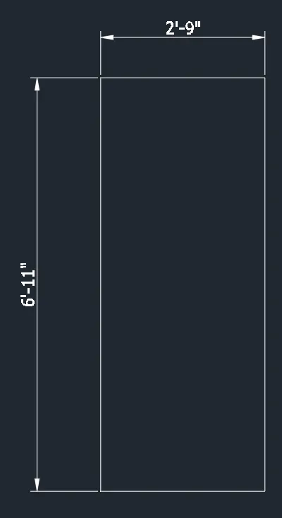
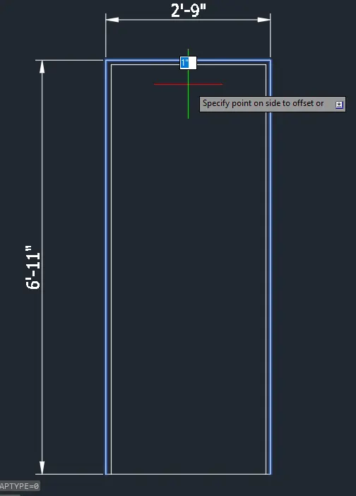
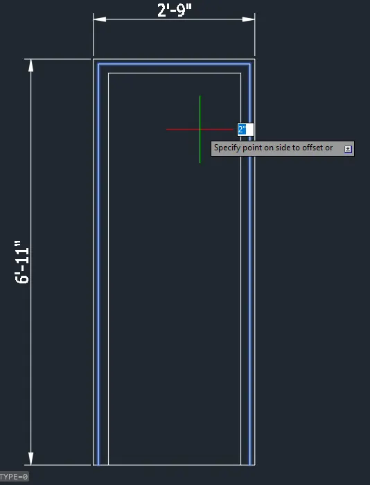
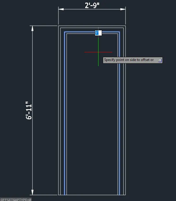
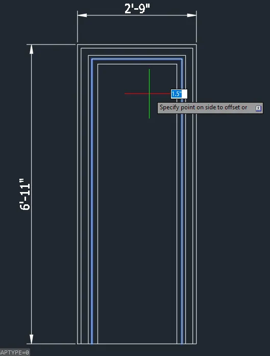
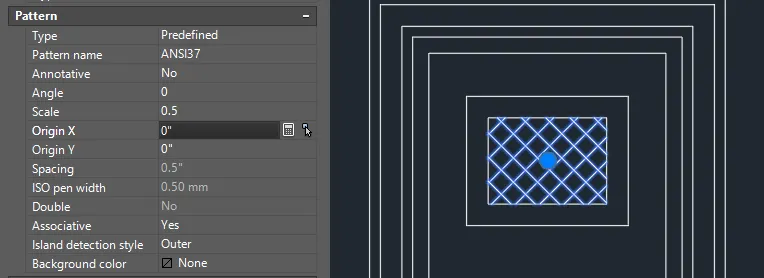
- Add hatch for the net.
- Copy door knob from D1.
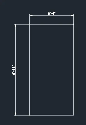
--> Proceed to D4.
- Do the same procedures as above. Utilize line, fillet, copy, and offset tool to finish the sketches.
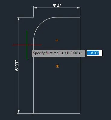
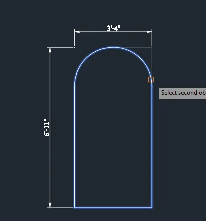
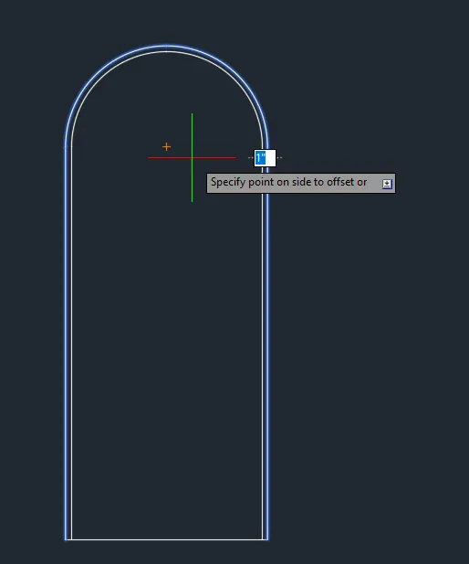
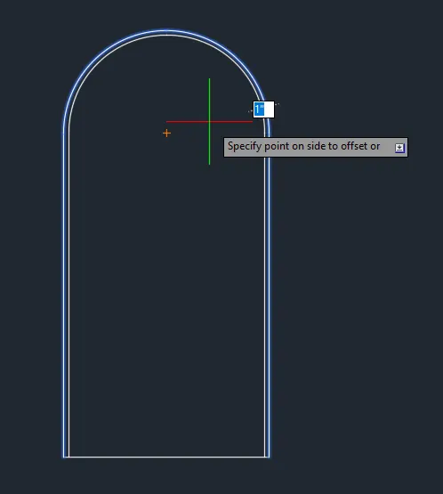
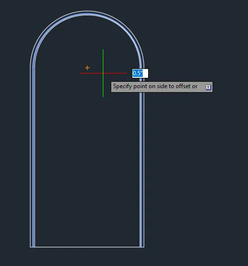
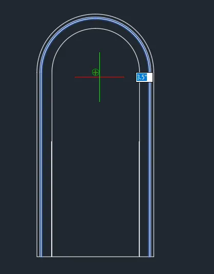
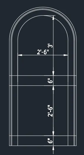
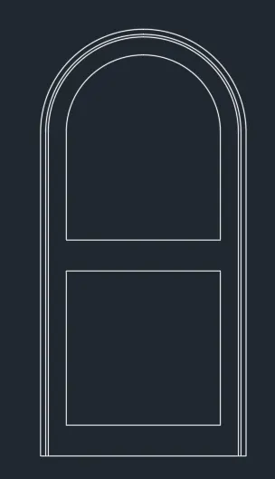
- Join the lines for ease of offset.
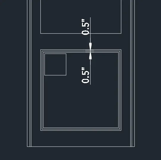
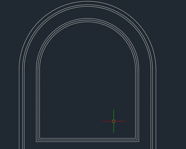
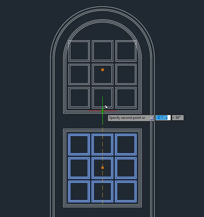
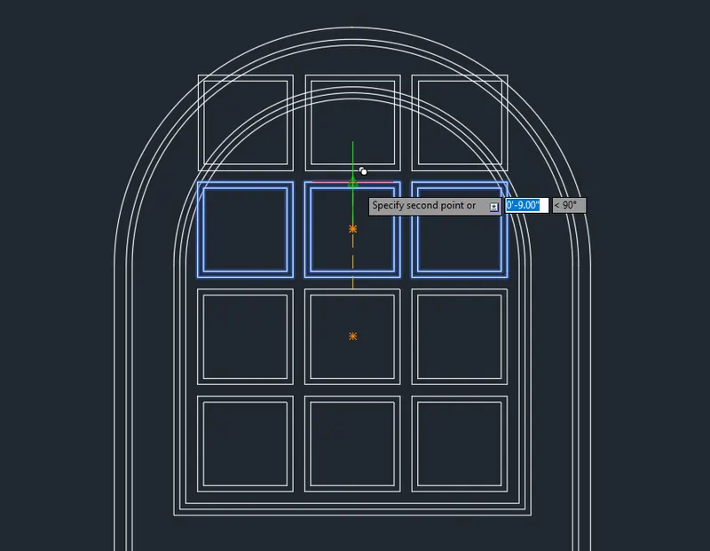
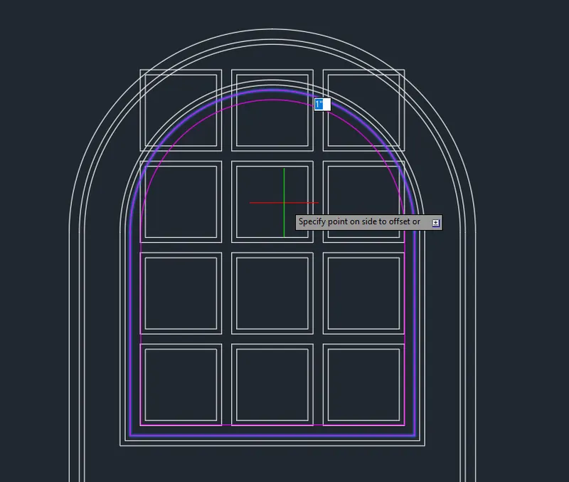
- Trim outside the created line.
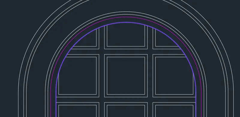
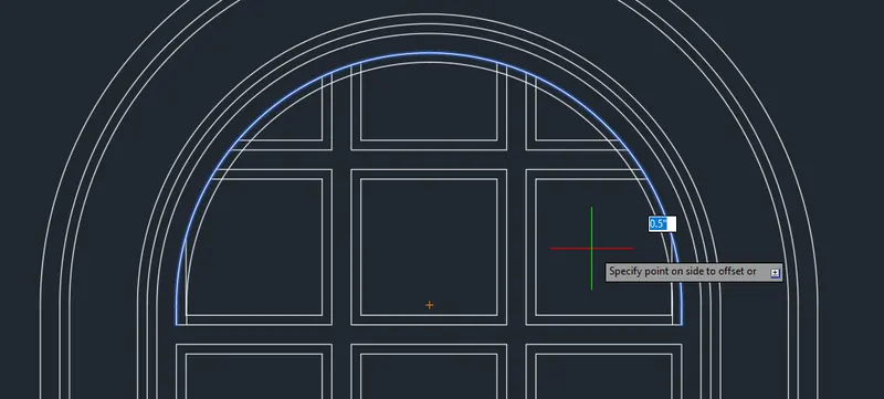
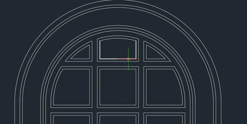
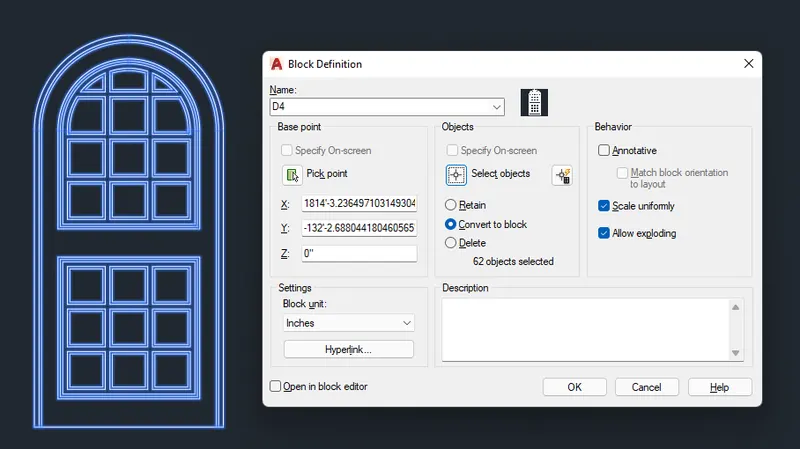
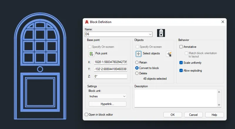
- You can edit the block using the block editor.
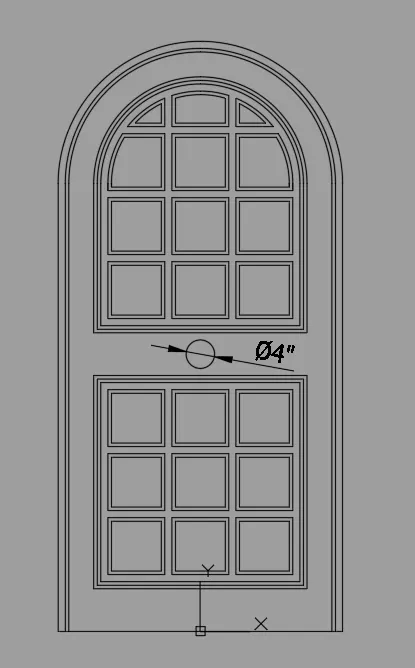
--> Proceed with Door 5. use D4 as base for better utilization.

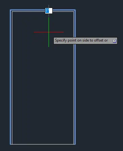
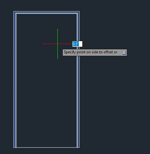
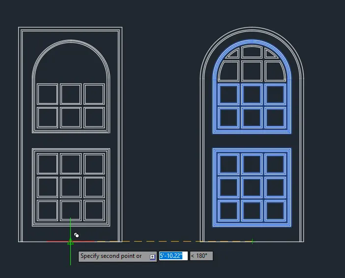
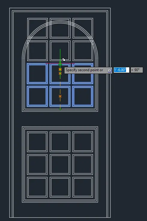
- Trim unnecessary lines.
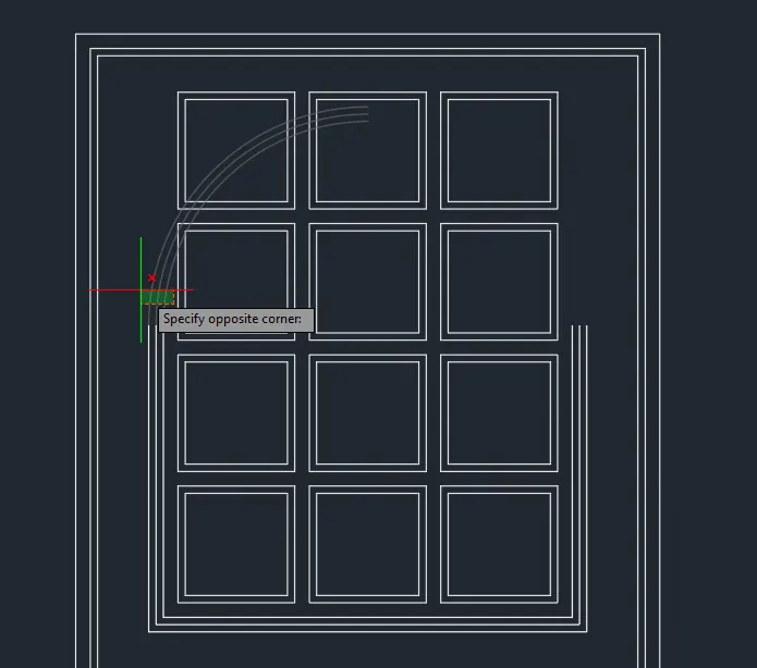
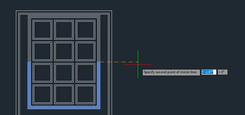
- Mirror the bottom part to close. Or use polyline edit to close the polylines.
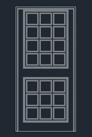
- Adjust the spacing using the move tool.
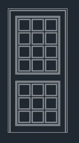
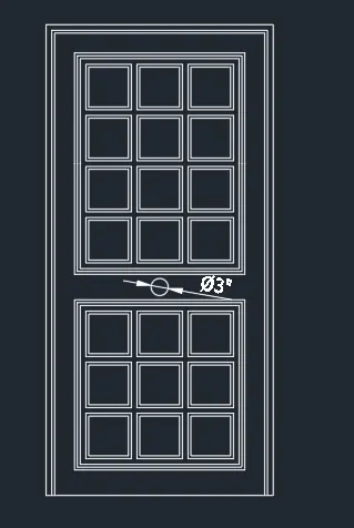
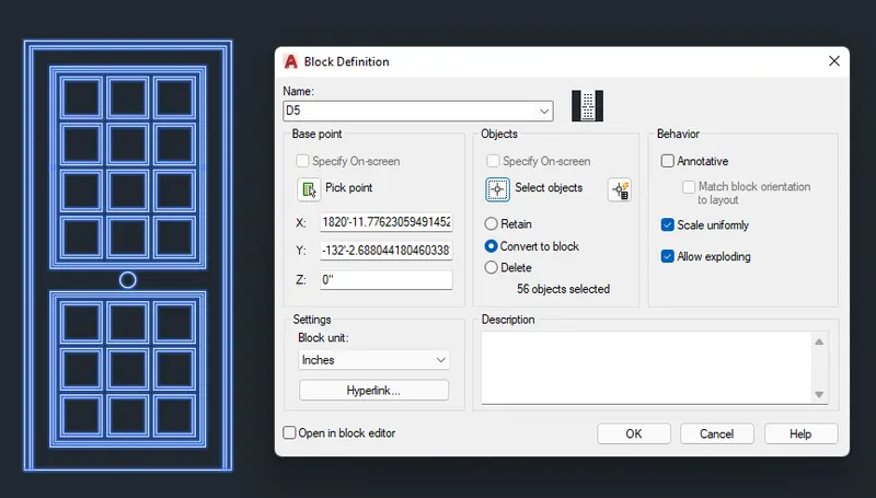
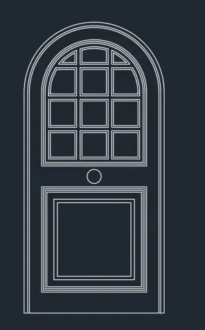
--> Proceed with D6. Use D4 as base then copy traits from D2.
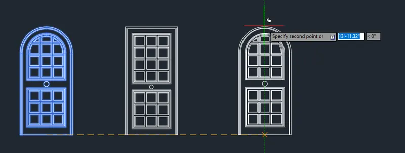
- Explode block to edit. Then delete unnecessary lines.
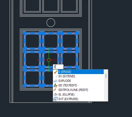
FINAL PRODUCT:
***************
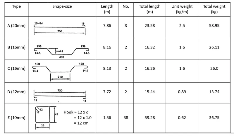
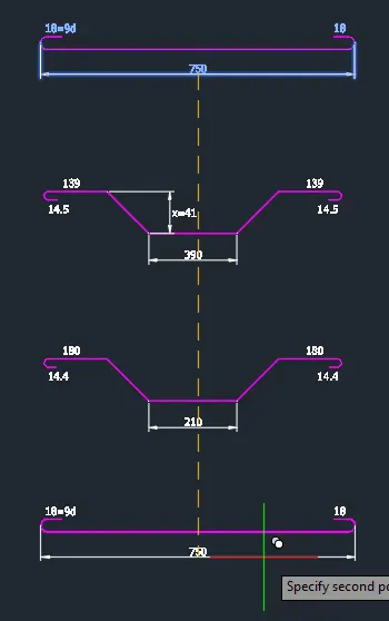
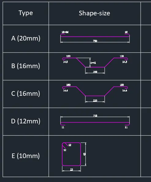
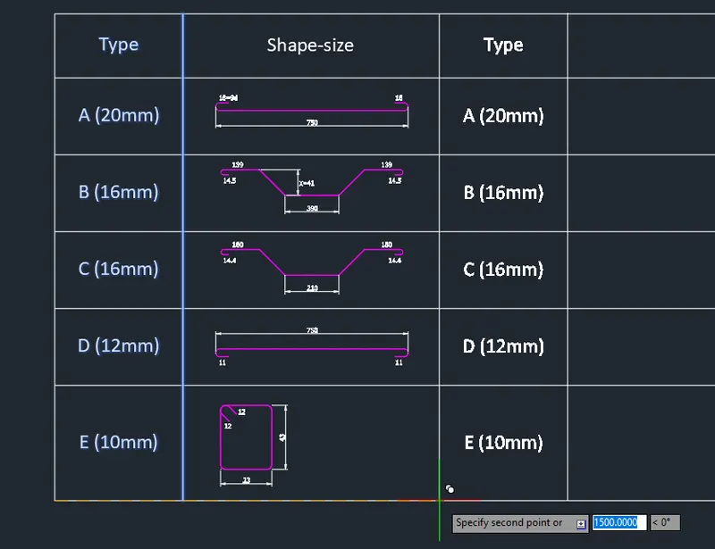
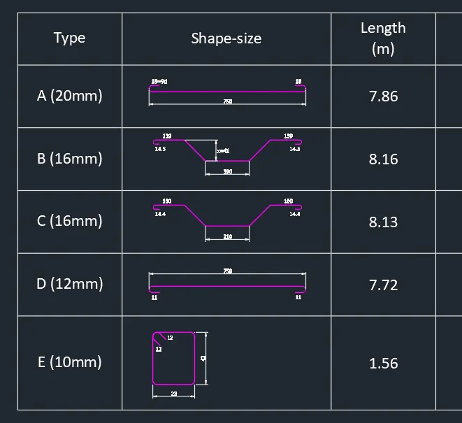
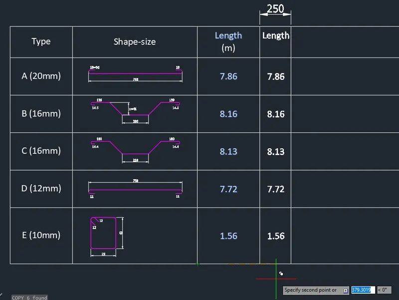
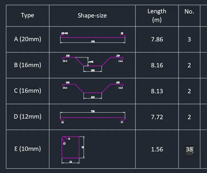
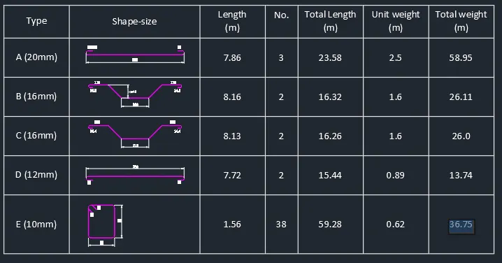
E) Create each shape as a block as shown in the Figure. Save the block and insert them on the table as shown in the Figure.
PROCEDURE:
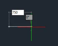
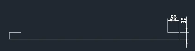
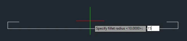
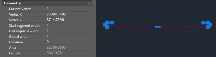
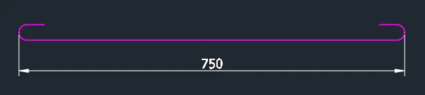
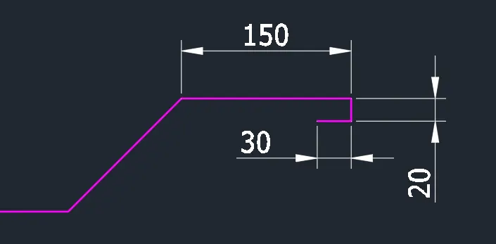
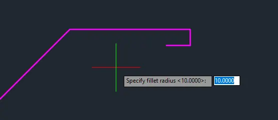
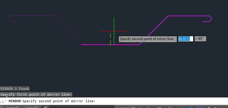
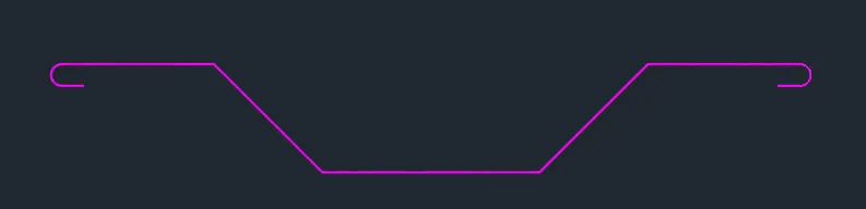
- Proceed with the first sketch. Use line and fillet command to create the sketch.
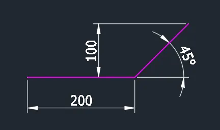
- Dimensions used are assumptions only and can be adjusted. These dimensions are for sketch representation only.

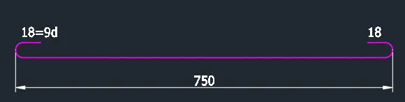
- Proceed with the next symbol.

- Add texts and dimensions. Edit the dimension by changing the text inside.
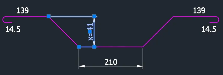
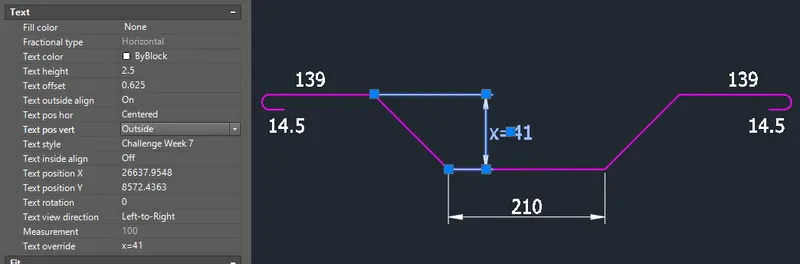
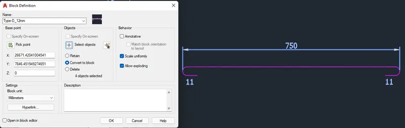
- Make it as a block.
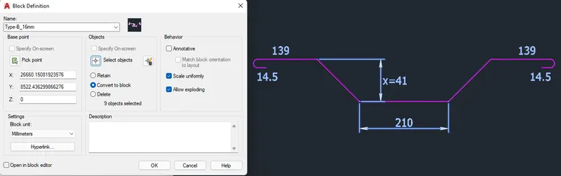
- You can enter the block to edit any missed information.
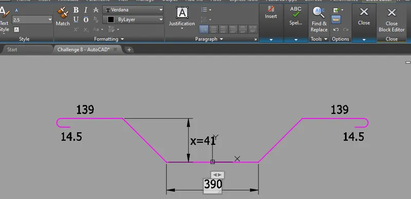
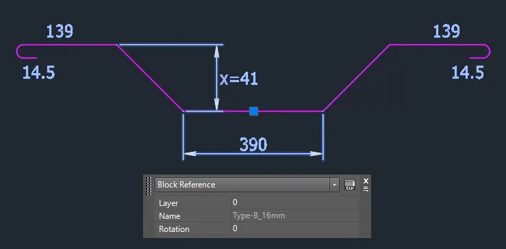
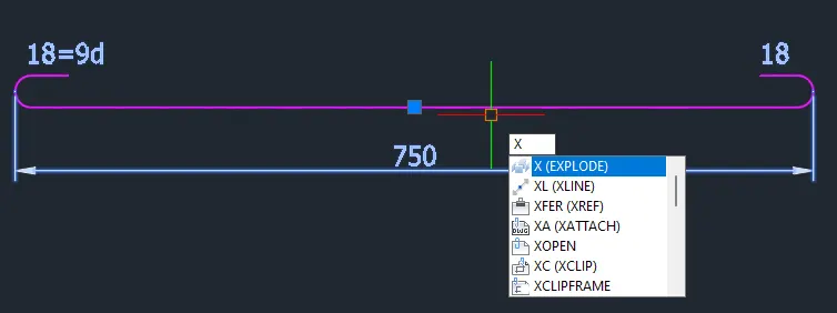
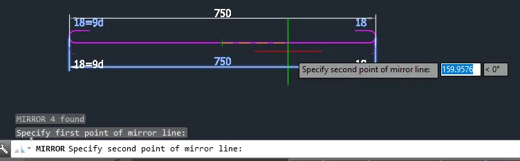
- Copy the 16mm block to create the other 16mm block. Then explode the block to edit.
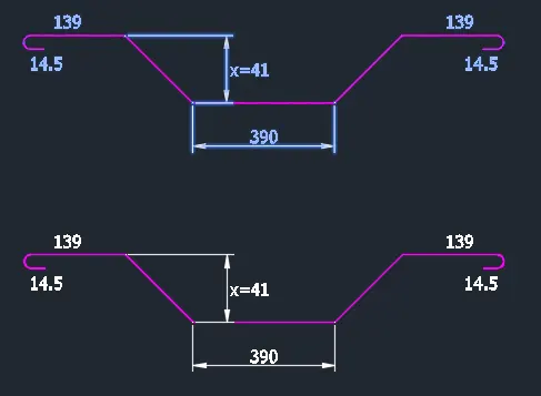
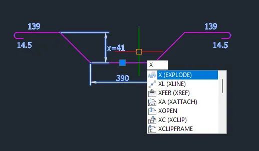
- Change texts and make it the next block.
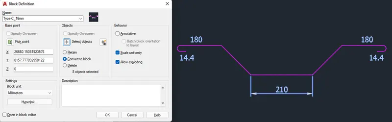
- Proceed to the next one. Do the same procedure as above.
- Proceed to the last detail.
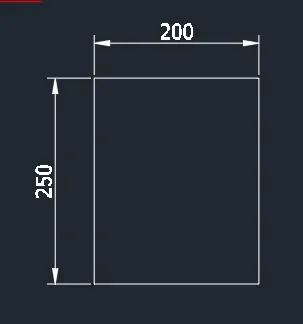
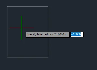
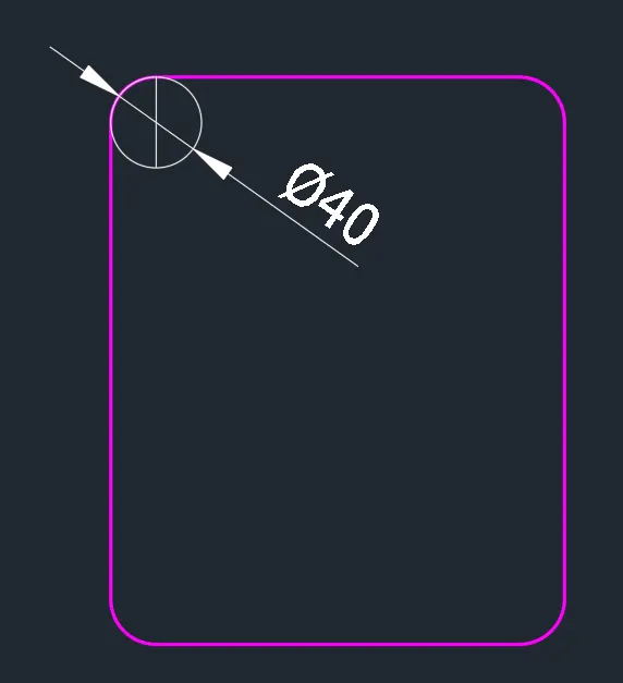
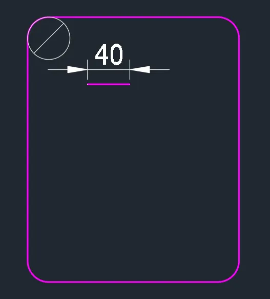
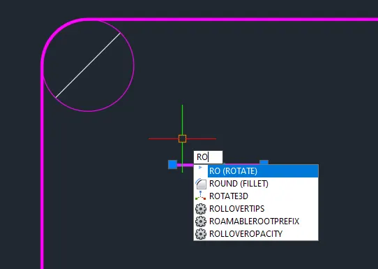
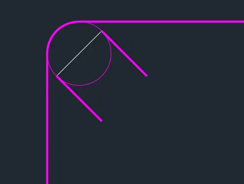
- Trim and join to finsih.
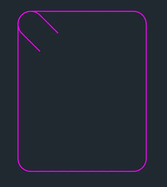
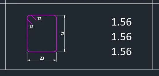
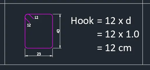
- Add texts and dimension. Double click the dimension text to edit the text.
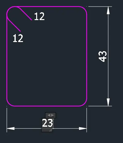
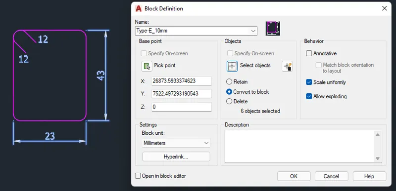
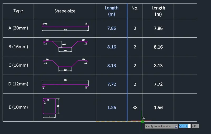
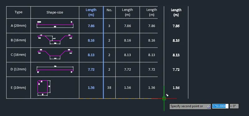
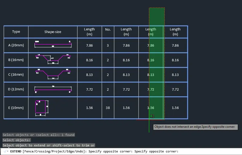
- Add the table to complete.
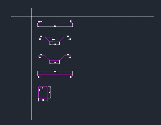
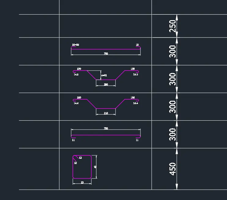
- Add texts together with the boundaries.
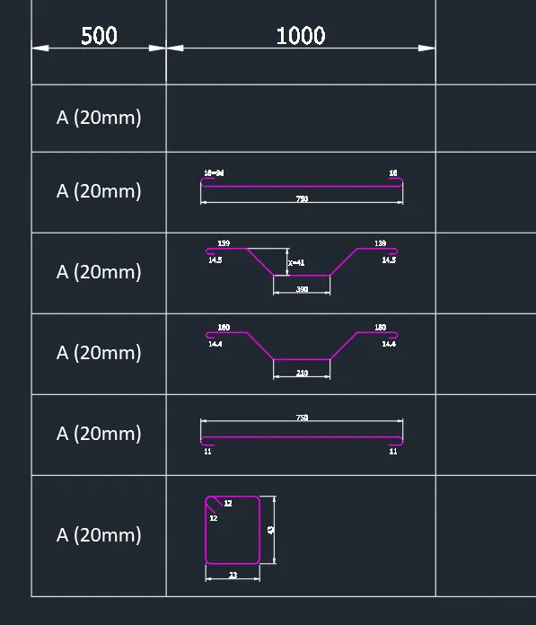
FINAL PRODUCT:

********************************************************
3. Conclusion
***************
The use of blocks in AutoCAD software is a usefull way to save objects or block objects and use them in other drawings. This will create time saving sketches like doors, windows or other architecturals items that is seldom included for drawing presentation.
This is a revolutionary command that allows the user to click multiple AutoCAD objects with one click. It also applies commands and parameters that is useful in sketching building plans.