Creating Bar Bending schedule, Different Door types, and Creation of standard drawing templates using AutoCad
Q1
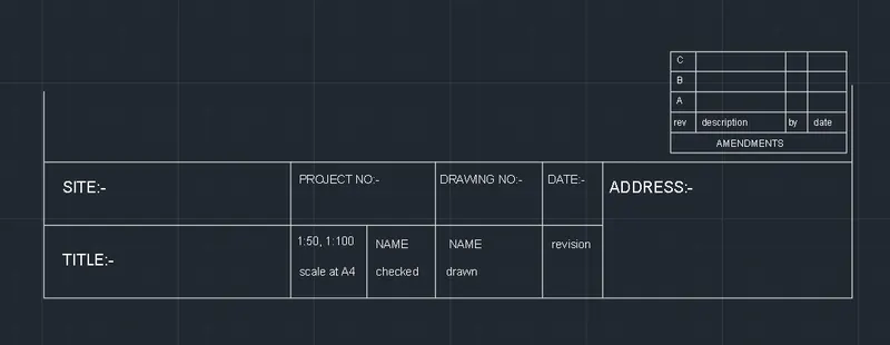
AIM:- To create a given template and convert it to block
- take a line command
- specify the first point
- then draw the table using line command as per the required
- then take a mtext command
- specify the first point
- and write the text as given in the table
- after creating the table and writing the text convert it to block
- take a block command
- give the name to the command as custom1_titleblock
- select the object
- select the pick point
- then click on ok
- then the block is created
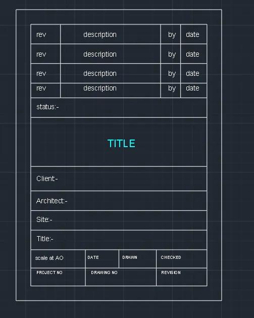
AIM:- To create a given second template and convert it to block
- take a line command
- specify the first point
- then draw the table using line command as per the required
- then take a mtext command
- specify the first point
- and write the text as given in the table
- after creating the table and writing the text convert it to block
- take a block command
- give the name to the command as custom2_titleblock
- select the object
- select the pick point
- then click on ok
- then the block is created
Q2
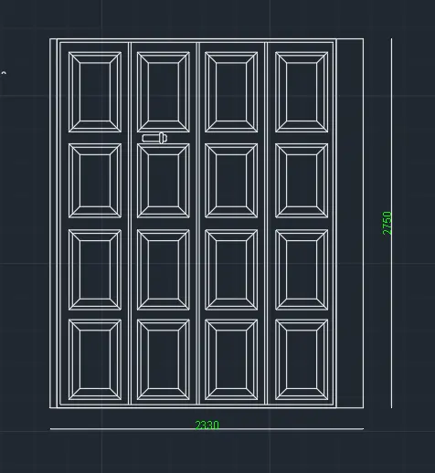
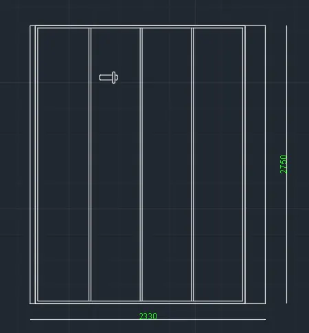
AIM:- to draw the door1 as per given dimensions
- take a line command
- specify the first point
- specify the next point as 2330
- specify the next point as 2750@<90
- specify the next point as 2330@<180
- then select c and close the command
- take an offset command
- specify the offset distance as 50
- select the objects to be offsetted
- now divide the door frame into 4 parts
- then draw panels by taking the rectangle command
- then take an offset command
- specify the offset distance
- select the objects to be offset to show the 3d view of the panel
- similarly, draw the other panels
AIM:- to draw the door2 as per given dimensions
- take a line command
- specify the first point
- specify the next point as 2330
- specify the next point as 2750@<90
- specify the next point as 2330@<180
- then select c and close the command
- take an offset command
- specify the offset distance as 50
- select the objects to be offsetted
- now divide the door frame into 4 parts
- then draw the lockset on the frame
- then convert the door to block
- take a block command
- give the name as door2
- select the objects
- select the pick point
- then click on ok
- the door is converted to block
Q3
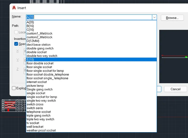
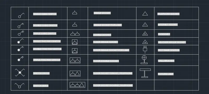
AIM:- To create a block legend of electrical fixtures
- create each symbol taking the commands as per the requirements
- assume the dimensions of each symbol approximately
- then convert each symbol to block
- take a block command
- select the object each symbol
- select the pick point
- name the object as given
- then click on ok
- then the symbol is converted to block
- similarly, convert each symbol into blocks by giving the object name
- then draw a table/legend as required
- insert each block in the legend
- take an insert command
- select the block
- then click on the pick point
- add the block to the legend
- then name the block in the legend
- from the insert, toolbar select field command
- then the named object category
- select the block name from the list
- place the text in the legend
- similarly, name the other blocks also in the legend
Q4
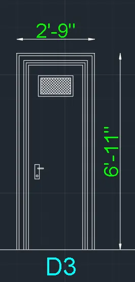
AIM:-to draw the door frames as per the given dimensions
- take a line command
- specify the first point
- specify the next point as 2'10"
- specify the next point as 6'11" <90
- specify the next point as 2'10"<180
- specify the next point as 6'11"<270
- then take an offset command to show the width of the frame
- then draw the door
- draw the lockset
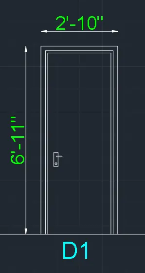
AIM:- To draw the door frame with a glass panel at the top and the opening in the bottom of the door frame with the lockset at the center
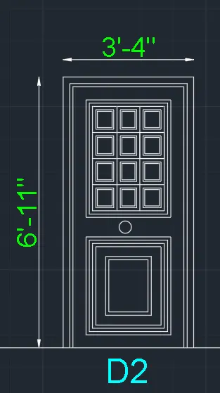
AIM:- To draw the door frame with the mesh opening at the top and the lockset
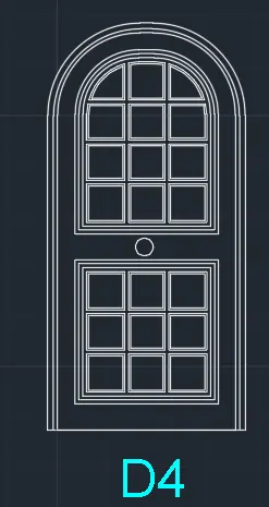
AIM:- to draw the door frame with an arc at the top and glass panels at the top and bottom of the door frame
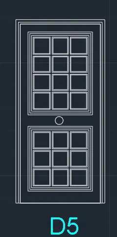
AIM:- To draw the door frame with glass panels at the top and bottom of the door frame
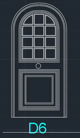
AIM:-To draw the door frame with a circular arc at the top of the frame with glass panels and opening in the door
Q5
AIM:- To create a bar bending schedule
- taka a line command and draw the sections as given
- convert each section into a block
- take a block command
- name the command
- select the object and add the pick point
- Click on ok and the block is created
- now take a line command and draw the table
- now insert the block in the table
- take an inset command
- select the block to be inserted
- Click on the pick point and add the block to the table
- add the text as required
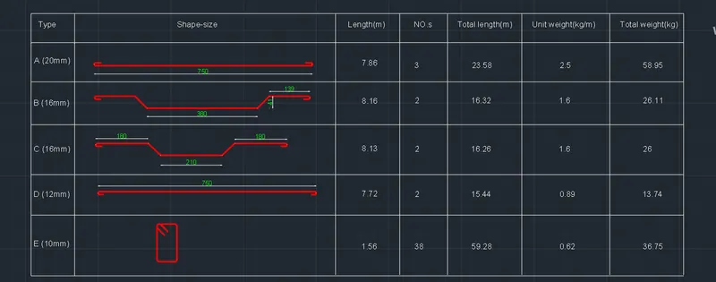
LIST OF BLOCKS CREATED