Creating Bar Bending schedule, Different Door types, and Creation of standard drawing templates using AutoCad
Q1
answer
Aim : To create the template as shown in the figure
Procedure
Step 1
- Open autoCAD and set units
- create layers for table and text
Step 2
- select line tool or table tool to draw the table
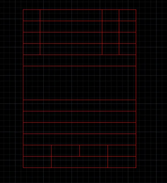
STEP 3
- select mtext and add text at the places as per drawing given
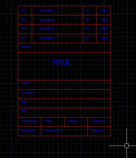
Step 4
- select line tool or table tool and create the table as given
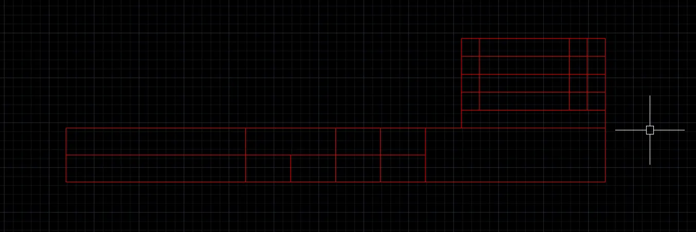
step 5
- select mtext and add the text as per requirement
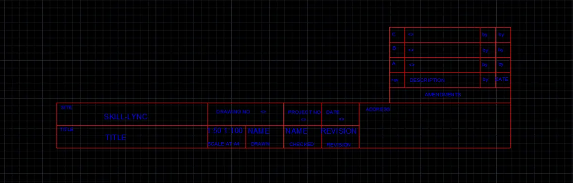
STEP 6
- command "B" to view blocks dialog box
- give the names as per requirement
- select the object
- and the blocks was created as below
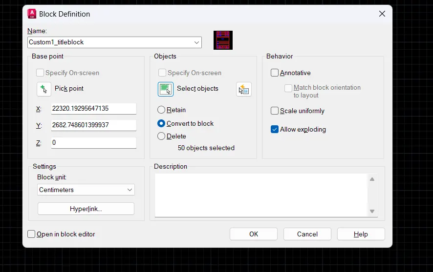
STEP 7
- result as shown of blocks
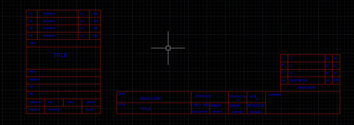
Q2
ANSWER
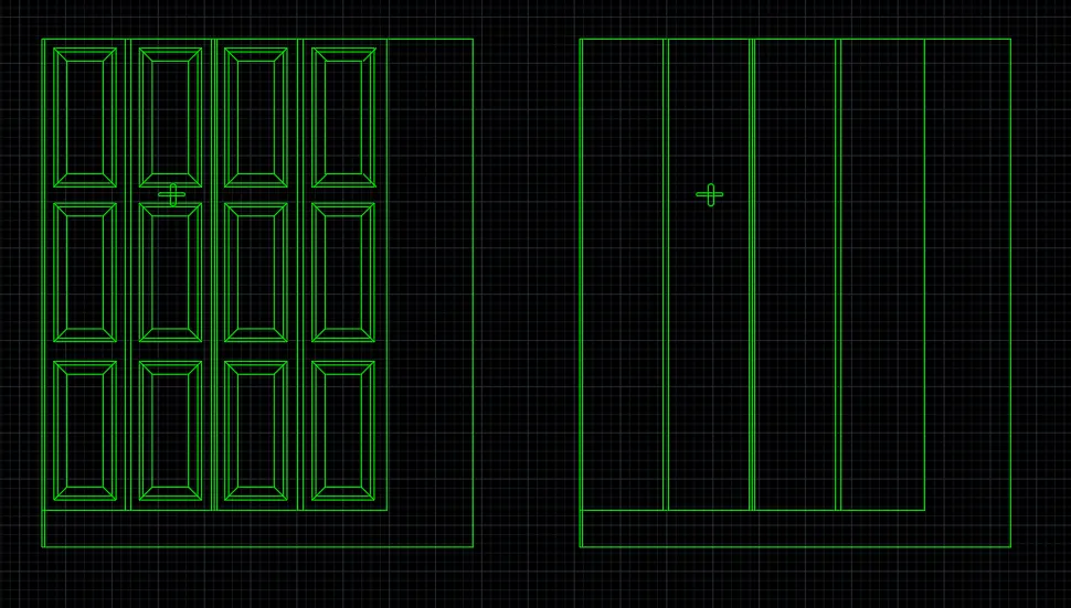
AIM : To Create the doors as shown in Figures. and making them as blocks as per specifications
PROCEDURE
STEP 1 :
- open a new AutoCAD file and set units
- set limits to 100,100
- create layers for table and text
STEP 2 :
- select "xl" to draw outlines
- select offset tool and give sufficient distances as per specifications
- trim off the remaining portion
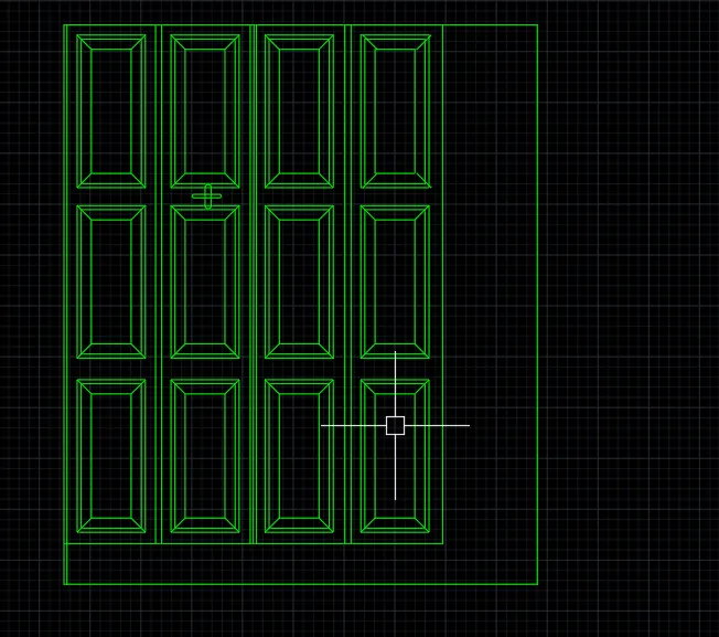
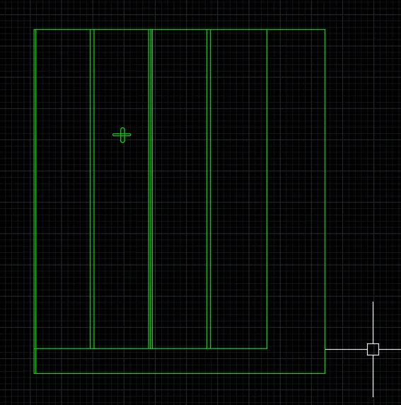
STEP 3:
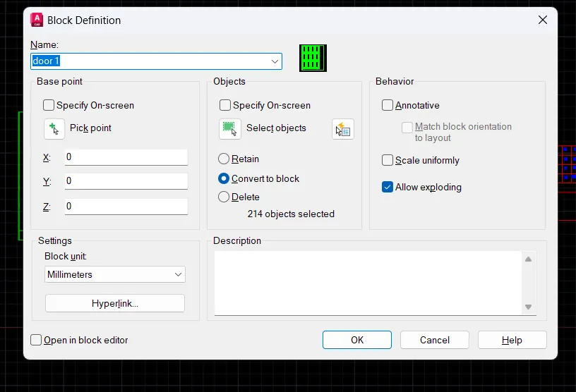
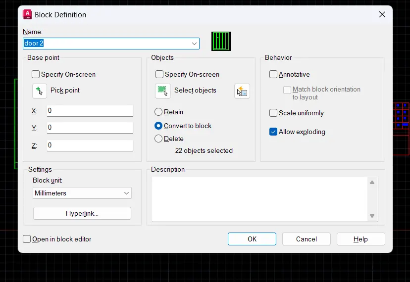
- command "B" to view blocks dialog box
- give the names as per requirement
- select the object
- and the blocks was created as below
STEP 4
- result as shown of blocks
Q3
ANSWER
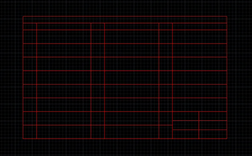
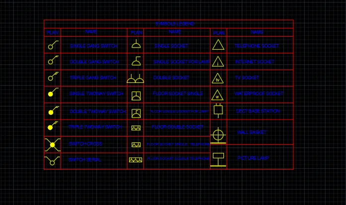
AIM : To Create the legend as shown in Figures. and making them as blocks as per specifications
PROCEDURE
STEP 1 :
- open a new AutoCAD file and set units
- set limits to 100,100
- create layers for table and text and symbols
STEP 2 :
- select "xl" to draw outlines
- select offset tool and give sufficient distances as per specifications
- trim off the remaining portion to create a table
STEP 3
- use circle and line tool to create different symbols as given
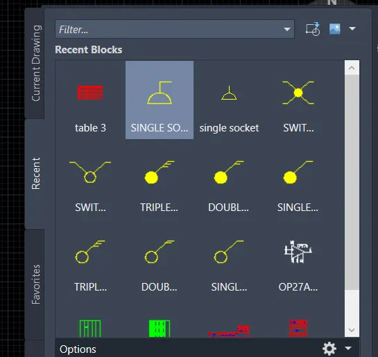
- command "B" to view blocks dialog box
- give the names as per requirement
- select the object
- and the blocks was created as below
STEP 4
- insert the blocks in the table as given
STEP 6
- the legend is created as per drawing
Q4
ANSWER
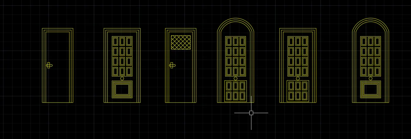
AIM : To Create the doors as shown in Figures. and making them as blocks as per specifications
PROCEDURE
STEP 1 :
- open a new AutoCAD file and set units
- set limits to 100,100
- create layers for table and text
STEP 2 :
- select "xl" to draw outlines
- select offset tool and give sufficient distances as per specifications
- trim off the remaining portion
STEP 3:
- command "B" to view blocks dialog box
- give the names as per requirement
- select the object
- and the blocks was created as below
STEP 4
- result as shown of blocks
Q1
ANSWER
AIM : To Create the templates as shown in Figures. and making them as blocks as per specifications
PROCEDURE
STEP 1 :
- open a new AutoCAD file and set units
- set limits to 100,100
- create layers for table and text
STEP 2 :
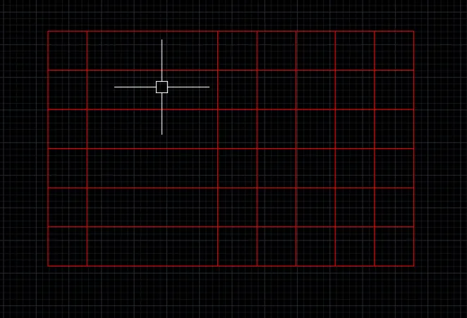
- select "xl" to draw outlines
- select offset tool and give sufficient distances as per specifications
- trim off the remaining portion to create a table
STEP 3
- use circle and line tool to create different symbols as given
- command "B" to view blocks dialog box
- give the names as per requirement
- select the object
- and the blocks was created as below
STEP 4
- insert the blocks in the table as given
STEP 6
- the legend is created as per drawing
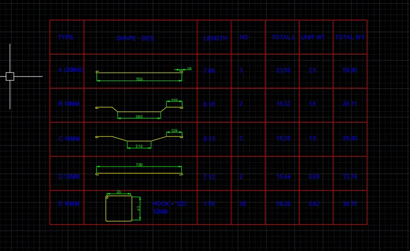
RESULT
The blocks of all diagrams given in the question are completed and shown wrt to the question in detailed formate