Creating Bar Bending schedule, Different Door types, and Creation of standard drawing templates using AutoCad
1. Create the templates as shown in Figures. Take the size of the title block as per industry standards or you can assume it as per the size of the paper. Use text and attributes wherever required. After creating the title block you need to save it as a block with names: Custom1_titleblock and Custom2_titleblock, respectively.
AIM:
To Create the given Block as per Industry Standards.
PROCEDURE:
Custom1_titleblock
- Create a out line with a standard dimension for a Title Block.
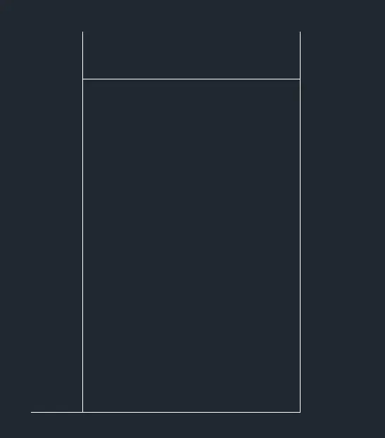
- Using Offset commend draw the needed lines for the title block as given in the drawing.
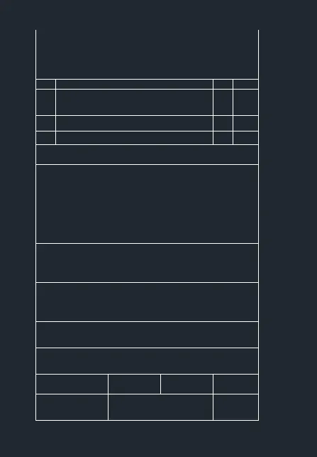
- Using MText commend the text were written as per the drawing.
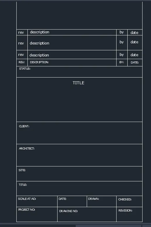
- Using properties of the line commend the Title block and some texts are change in color.
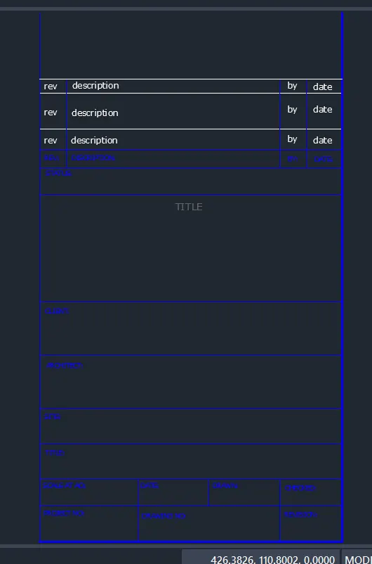
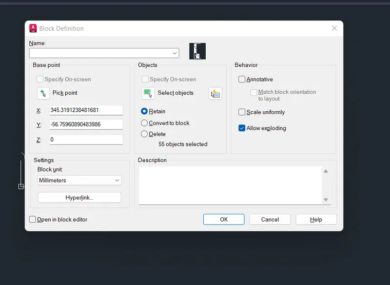
- Now we use the Block commend to create the Block.
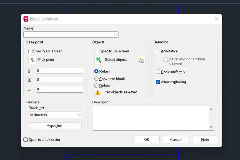
- Use Block Commend and Name the Block then Pick the base point and then select the whole object to create the Block.
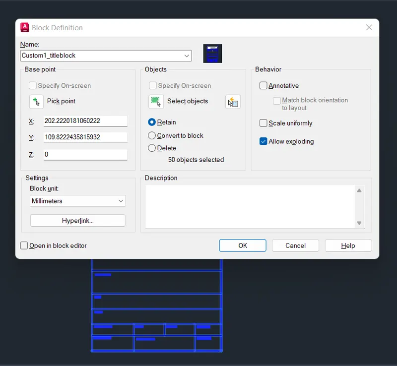
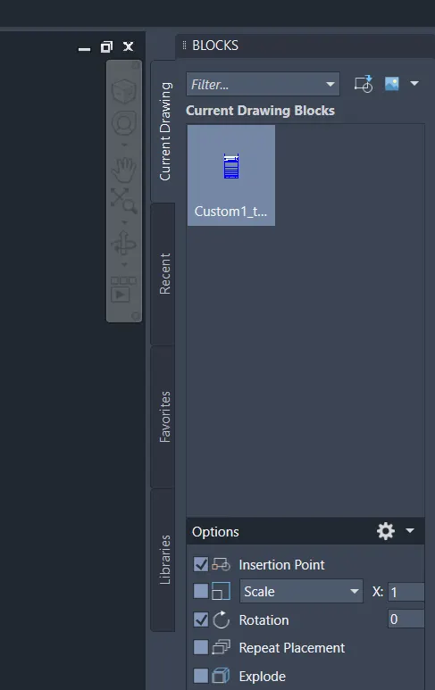
- The Custom1_Titleblock was created.
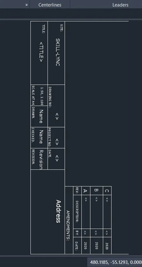
Custom2_titleblock
- Create a Title Block using line and Offset command.
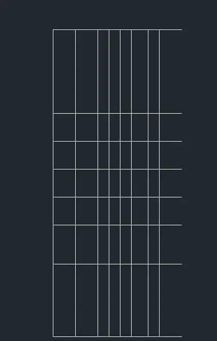
- Then using the Trim command erase the unwanted lines.
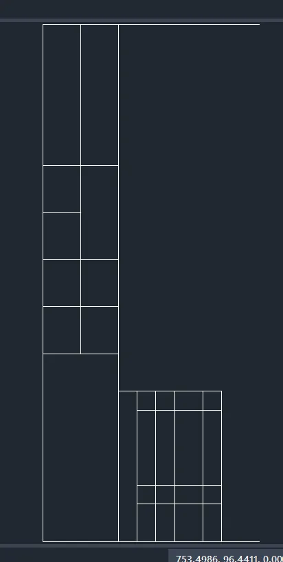
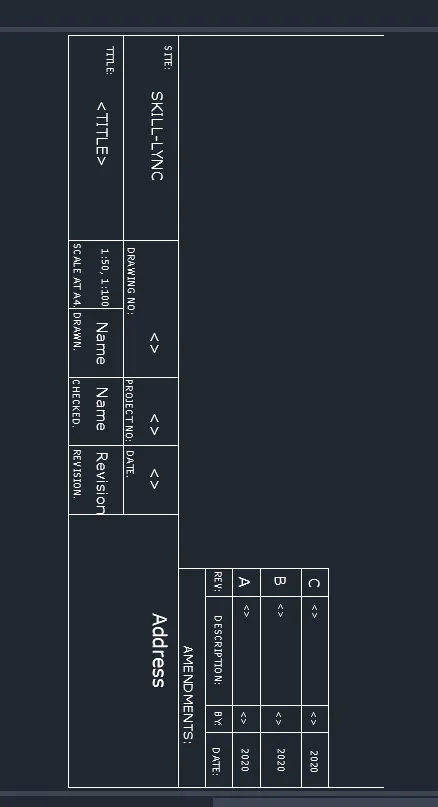
- Then Using the MText command the texts were written.
- Now use the Block command to create a block.
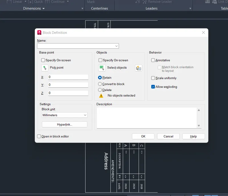
- Name the Block as Custom2_Titleblock and Pick the base point and select the whole object. Then the Block was created.
- Custom2_Titleblock
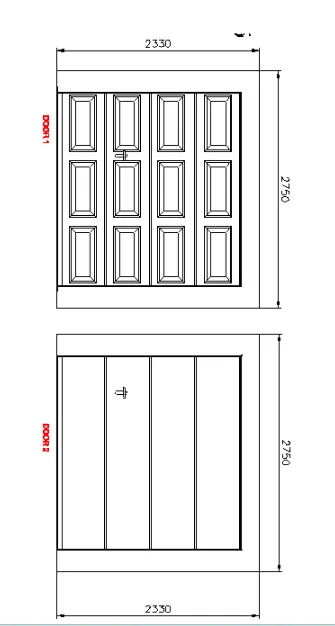
2. Create the doors type for warehouse as shown in the Figure. You need to create each door type as per standard size or given dimensions. Create the blocks of this door type after creating them.
AIM:
To create each door type as per standard size or given dimensions. Create the blocks of this door type after creating them.to create each door type as per standard size or given dimensions. Create the blocks of this door type after creating them.
PROCEDURE:
- Open the AutoCAD.
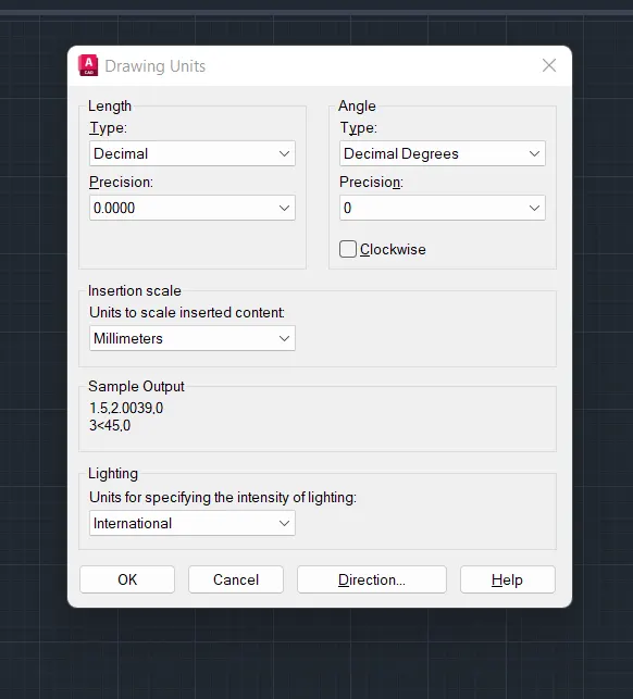
- Set the Units as Decimal and Scale as Millimeters.
- Then use a Rec command and create a rec with the dimension of 2750X2330mm.
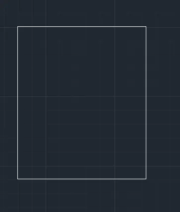
- Using an Offset command Create the lines for the doors with the assumed dimension.
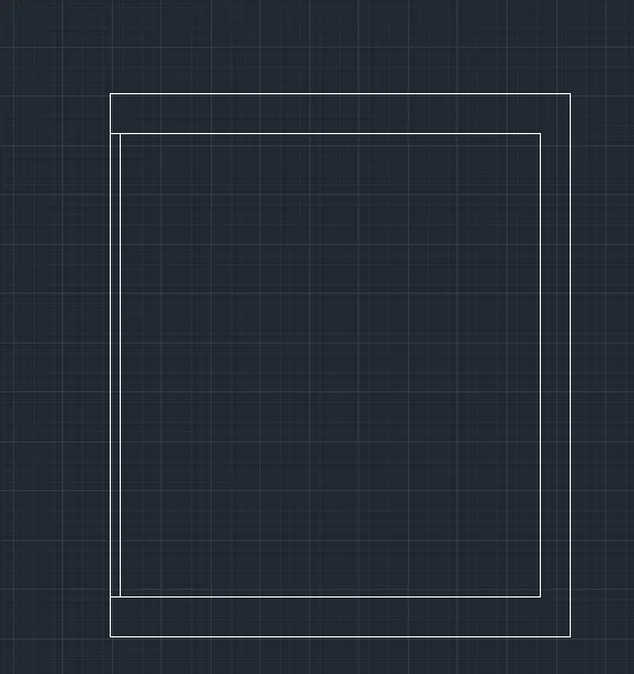
- Now create a Rectangle with an assumed dimensions like in the diagram for the door.
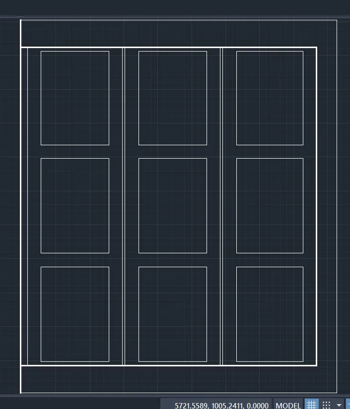
- Use Offset and Line command to draw the design of the door. And use copy command to create the number of same objects.
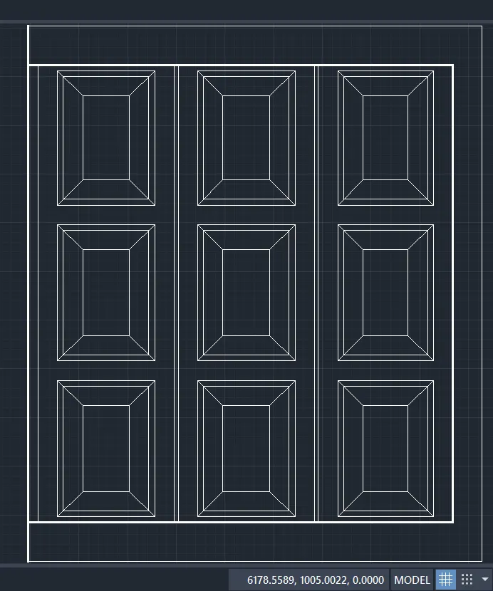
- Use Dim command to mark the dimensions of the door. And use MText command for the texts. The Door 1 is created.
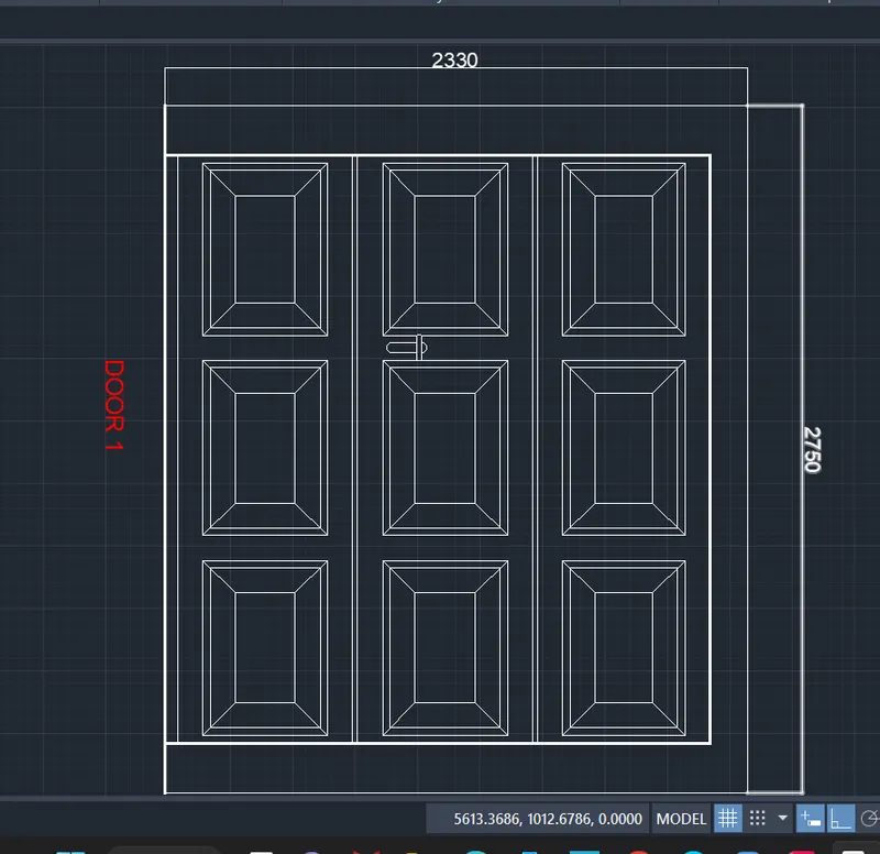
- For the second door we have to copy the Door 1 and use trim command and erase command to delete the designs of the door and unwanted lines of the door. The Door 2 is Created.
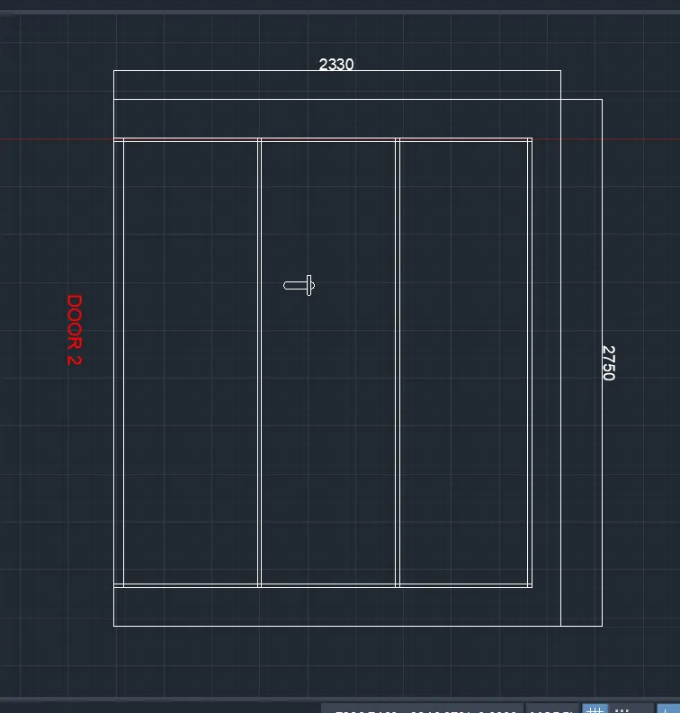
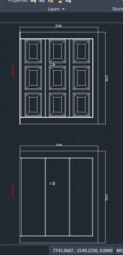
- Door 1 and Door 2
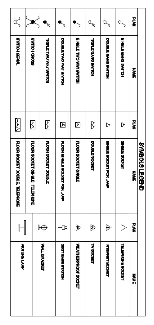
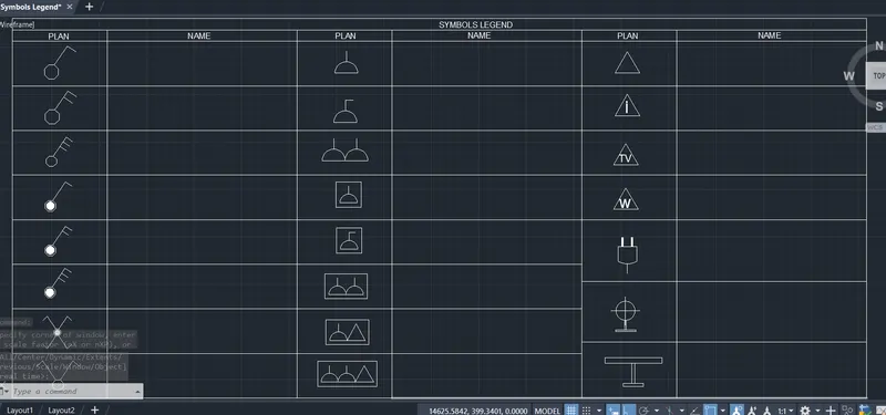
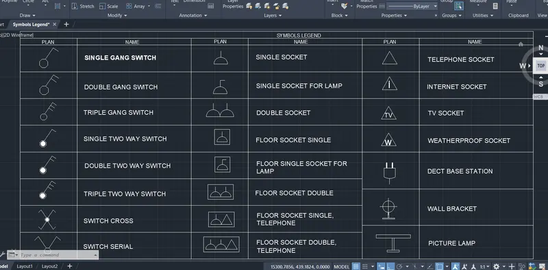
3. Create each symbol as a block with the name given in the legend. After creating the blocks arrange them in the legend as shown in the Figure.
AIM:
To Create each symbol as a block with the name given in the legend. After creating the blocks arrange them in the legend as shown in the Figure.
PROCEDURE:
- Open AutoCAD.
- Use Unit command and set the unit as Decimel and Millimeters.
- Use Polygon or cicle and Line command to create the Single gang switch.
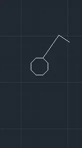
- Use Block command and Name the Block as Signle gang switch.
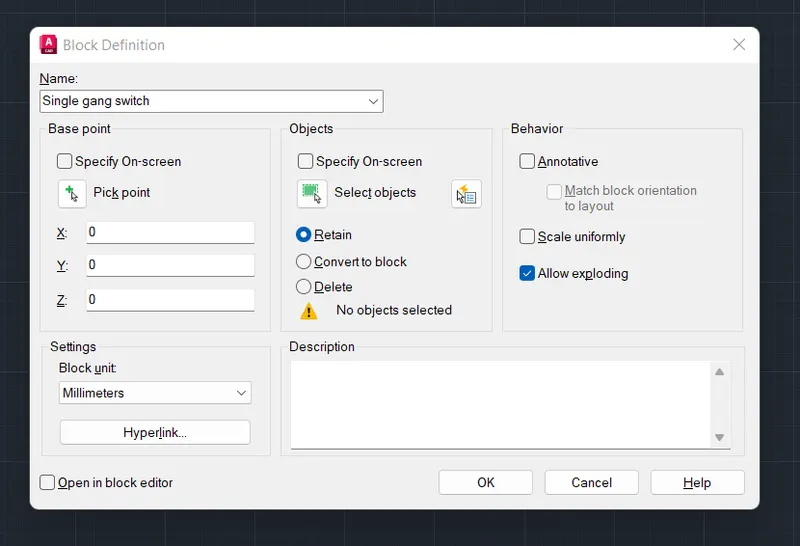
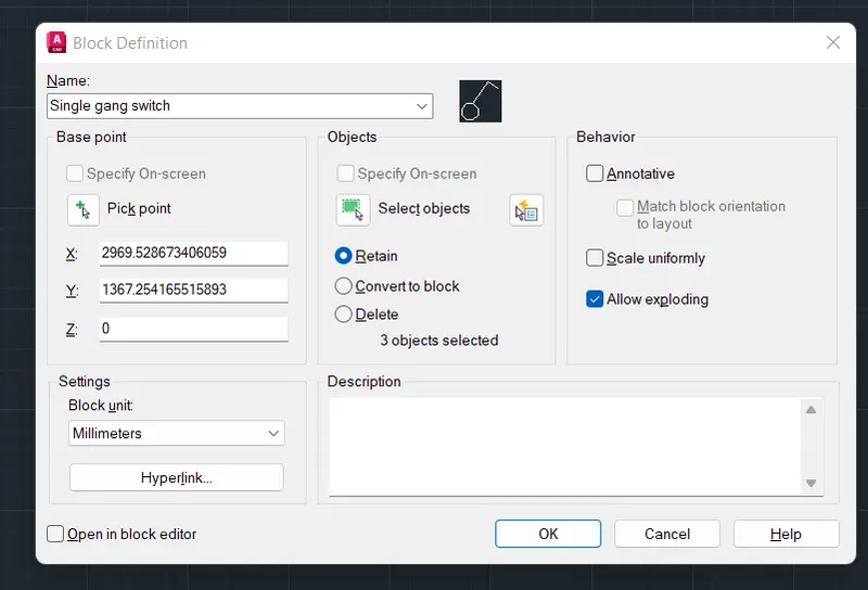
- And pick the base point and select the whole object.
- The Single gang Switch Block is created.
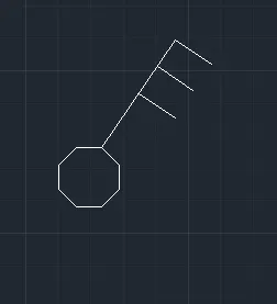
- Use Polygon or cicle, Line and Offset command to create the Double gang switch.
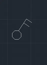
- Use Block command and Name the Block as Double gang switch.
- And pick the base point and select the whole object.
- The Double gang Switch Block is created.
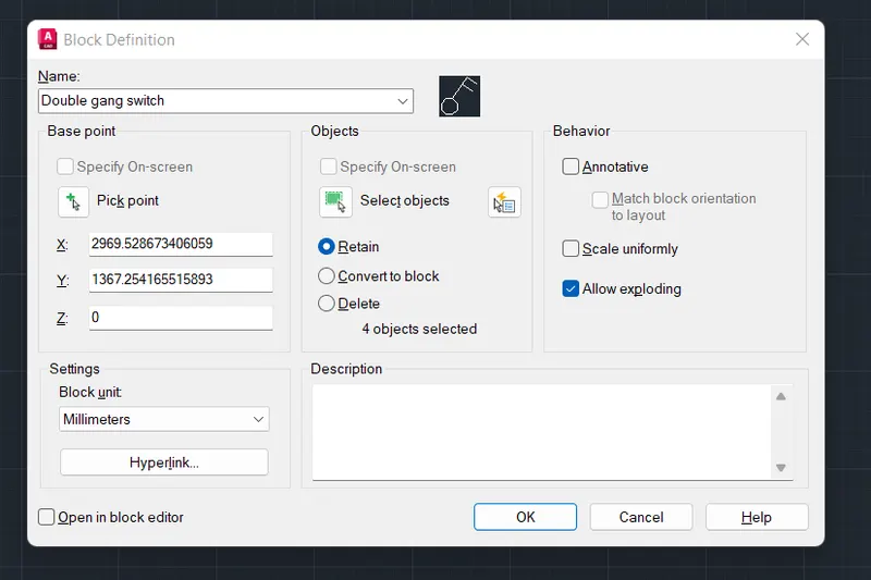
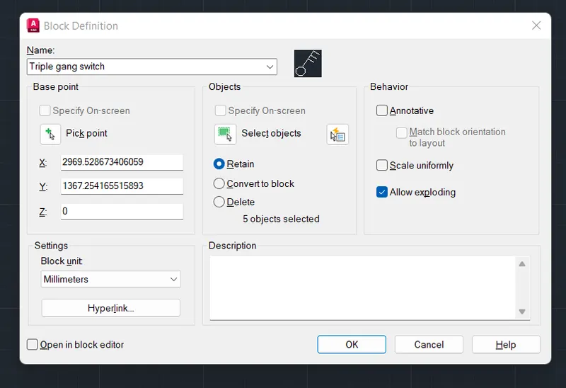
- Use Polygon or cicle, Line and Offset command to create the Triple gang switch.
- Use Block command and Name the Block as Triple gang switch.
- And pick the base point and select the whole object.
- The Triple gang Switch Block is created.
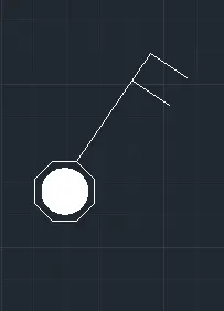
- Use Polygon or cicle, Line, Offset and Hatch command to create the Single two way switch.
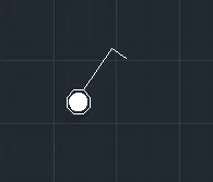
- Use Block command and Name the Block as Single two way switch.
- And pick the base point and select the whole object.
- The Signle two way Switch Block is created.
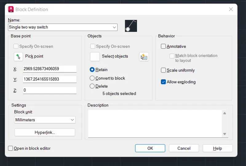
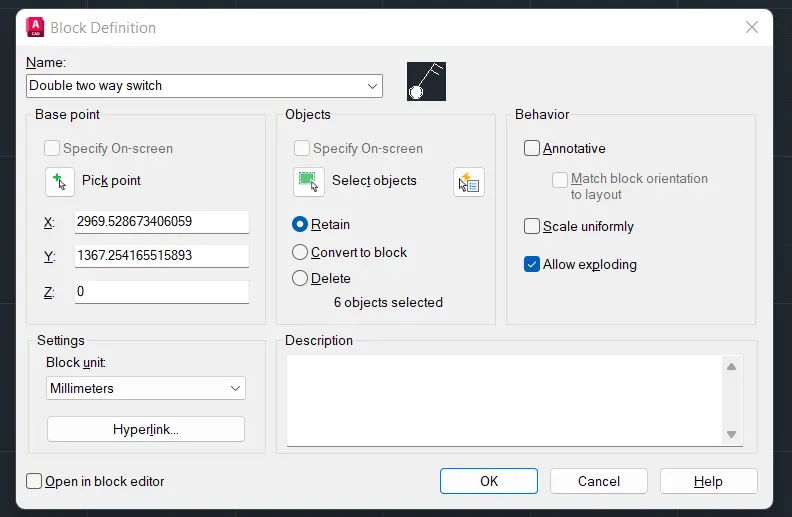
- Use Polygon or cicle, Line, Offset and Hatch command to create the Double two way switch.
- Use Block command and Name the Block as Double two way switch.
- And pick the base point and select the whole object.
- The Double two way Switch Block is created.
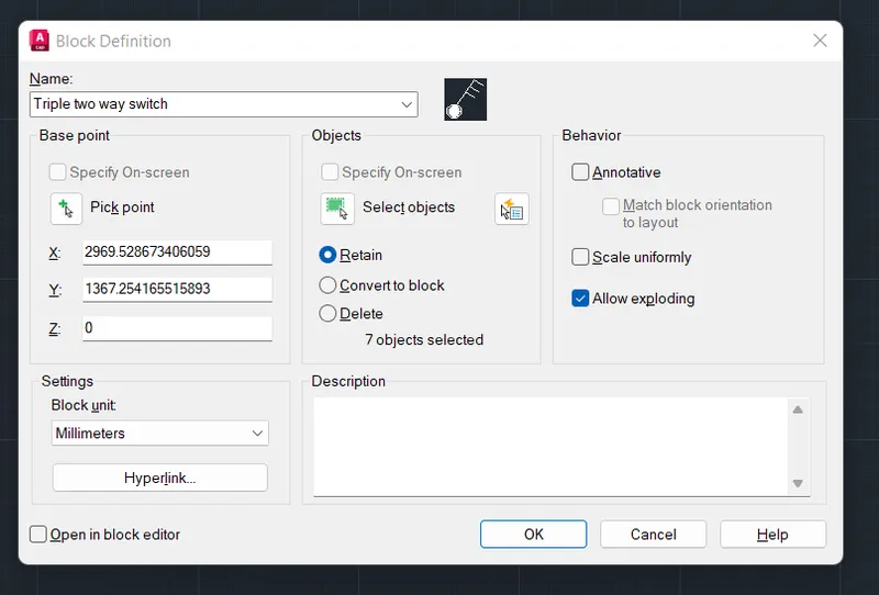
- Use Polygon or cicle, Line, Offset and Hatch command to create the Triple two way switch.
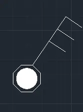
- Use Block command and Name the Block as Triple two way switch.
- And pick the base point and select the whole object.
- The Triple two way Switch Block is created.
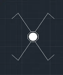
- Use Polygon or cicle, Line, Offset and Hatch command to create the Switch Cross.
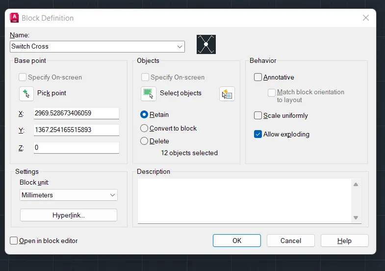
- Use Block command and Name the Block as Switch Cross.
- And pick the base point and select the whole object.
- The Triple two way Switch Cross is created.
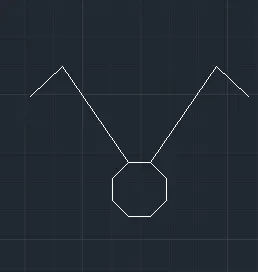
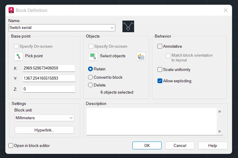
- Use Polygon or cicle, Line and Mirror command to create the Switch serial.
- Use Block command and Name the Block as Switch serial.
- And pick the base point and select the whole object.
- The Triple two way Switch serial is created.
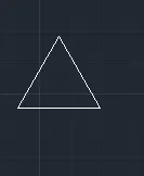
- Use Polygon command and give the number of sides as 3 to create the Telephone socket.
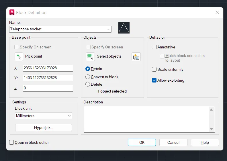
- Use Block command and Name the Block as Telephone Socket.
- And pick the base point and select the whole object.
- The Triple two way Telephone Socket is created.
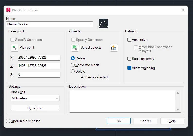
- Use Polygon command and give the number of sides as 3 to create the Triangle and use MText command or Rec command for the object inside the triangle.

- Use Block command and Name the Block as Internet Socket.
- And pick the base point and select the whole object.
- The Triple two way Internet Socket is created.
- Use Polygon command and give the number of sides as 3 to create the Triangle and use MText command for the object inside the triangle.

- Use Block command and Name the Block as TV Socket.
- And pick the base point and select the whole object.
- The Triple two way TV Socket is created.
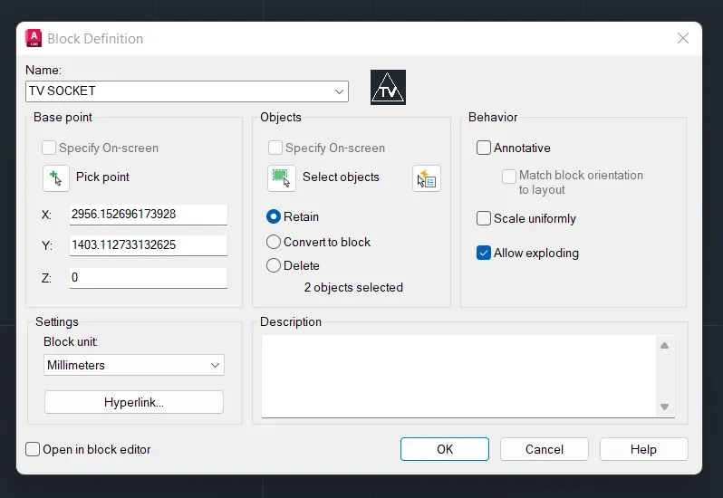
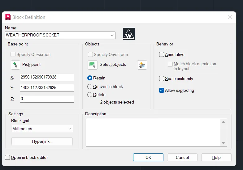
- Use Polygon command and give the number of sides as 3 to create the Triangle and use MText command for the object inside the triangle.

- Use Block command and Name the Block as Weatherproof Socket.
- And pick the base point and select the whole object.
- The Triple two way Weatherproof Socket is created.
- Use Line and Arc command To Create the Single Socket.
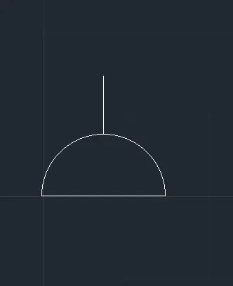
- Use Block command and Name the Block as Signle Socket.
- And pick the base point and select the whole object.
- The Signle Socket is created.
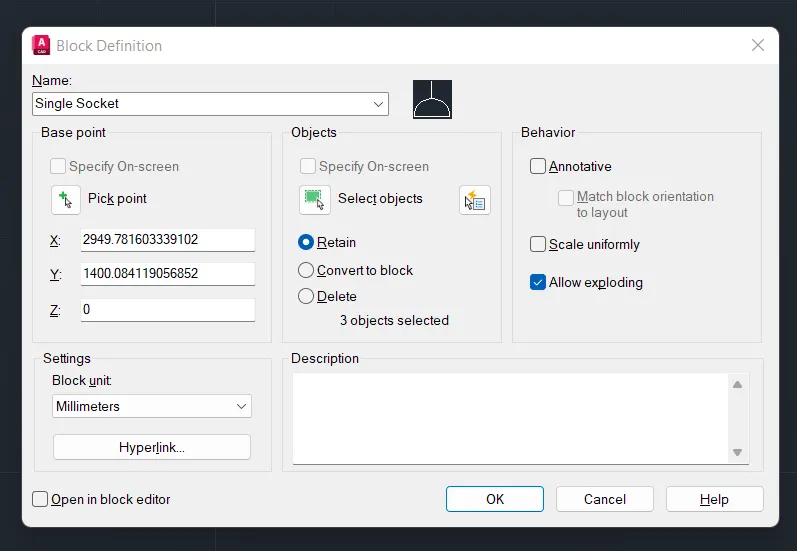
- Use Line and Arc command To Create the Signle Socket for Lamp.
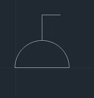
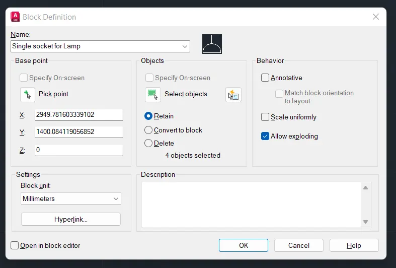
- Use Block command and Name the Block as Signle Socket for Lamp.
- And pick the base point and select the whole object.
- The Signle Socket for Lamp is created.
- Use Line, Arc and Copy command To Create the Double Socket.
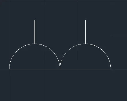
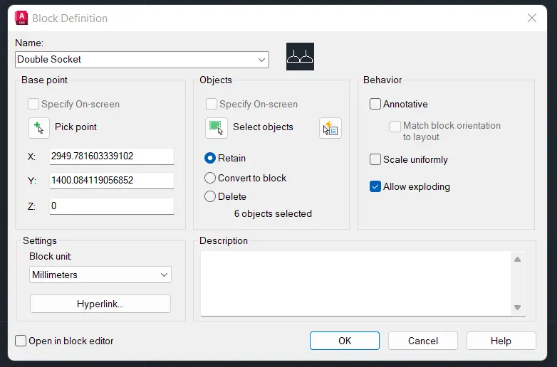
- Use Block command and Name the Block as Double Socket.
- And pick the base point and select the whole object.
- The Double Socket is created.
- Use Line, Arc and Rec command To Create the Floor Single Socket.
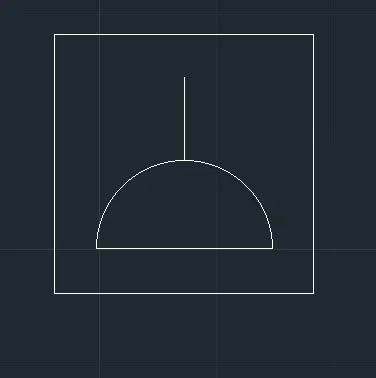
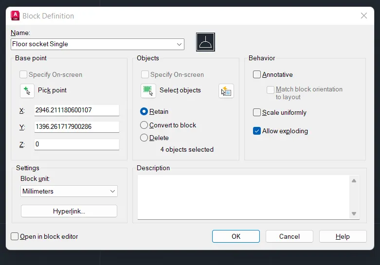
- Use Block command and Name the Block as Floor Single Socket.
- And pick the base point and select the whole object.
- The Floor Single Socket is created.
- Use Line, Arc and Rec command To Create the Floor Single Socket for lamp.
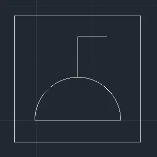
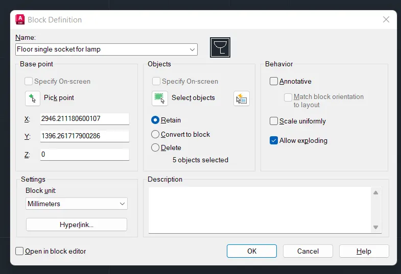
- Use Block command and Name the Block as Floor Single Socket for Lamp.
- And pick the base point and select the whole object.
- The Floor Single Socket for Lamp is created.
- Use Line, Arc, Rec and Copy command To Create the Floor Socket Double.
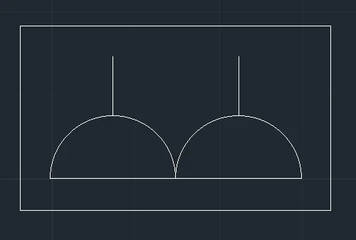
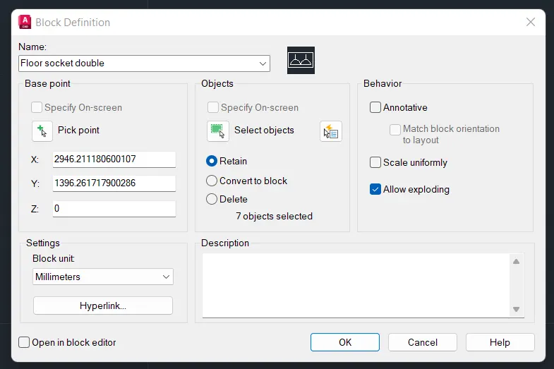
- Use Block command and Name the Block as Floor Socket Double.
- And pick the base point and select the whole object.
- The Floor Socket Double is created.
- Use Line, Arc, Rec and Polygon command To Create the Floor Single Socket,Telephone.
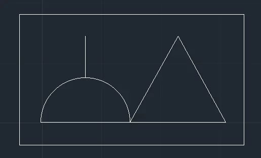
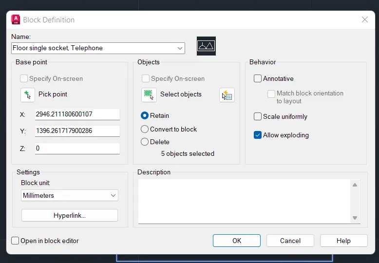
- Use Block command and Name the Block as Floor Single Socket, Telephone.
- And pick the base point and select the whole object.
- The Floor Single Socket, Telephone is created.
- Use Line, Arc, Rec, Polygon and copy command To Create the Floor Socket Double,Telephone.
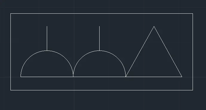
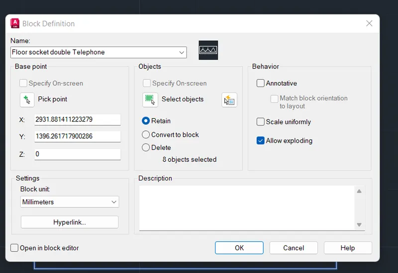
- Use Block command and Name the Block as Floor Socket Double, Telephone.
- And pick the base point and select the whole object.
- The Floor Socket Double, Telephone is created.
- Use Line and Arc command To Create the Dect Base Station.
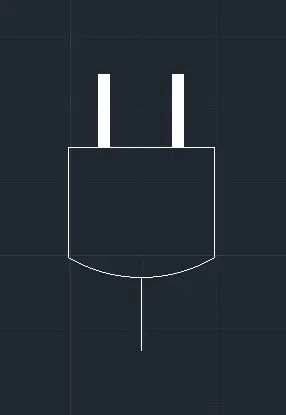
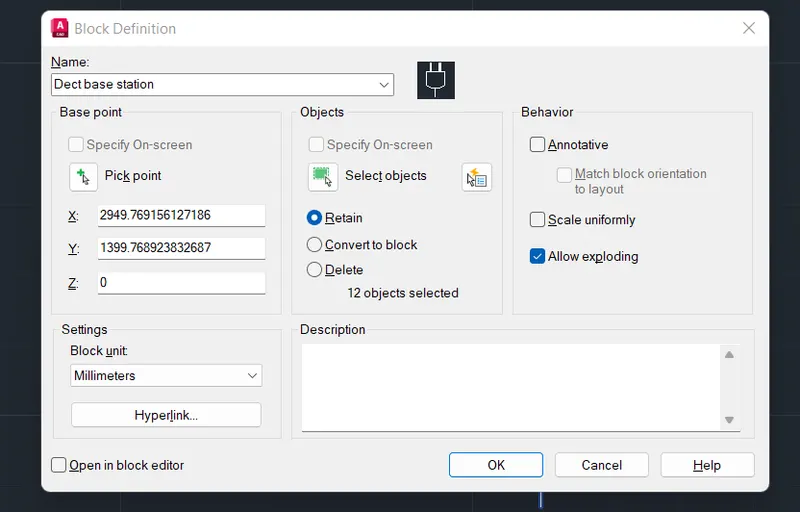
- Use Block command and Name the Block as Dect Base Station.
- And pick the base point and select the whole object.
- The Dect Base Station is created.
- Use Line and Circle command To Create the Wall Bracket.
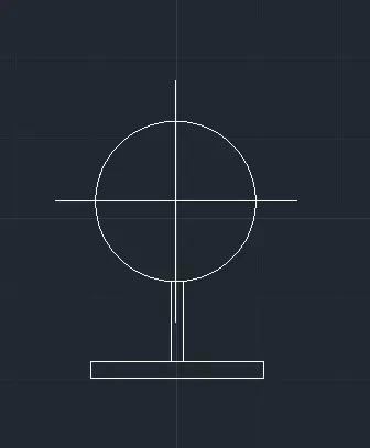
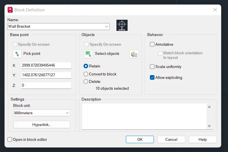
- Use Block command and Name the Block as Wall Bracket.
- And pick the base point and select the whole object.
- The Wall Bracket is created.
- Use Rec command To Create the Picture Lamp.
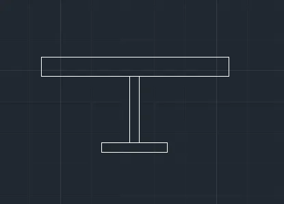
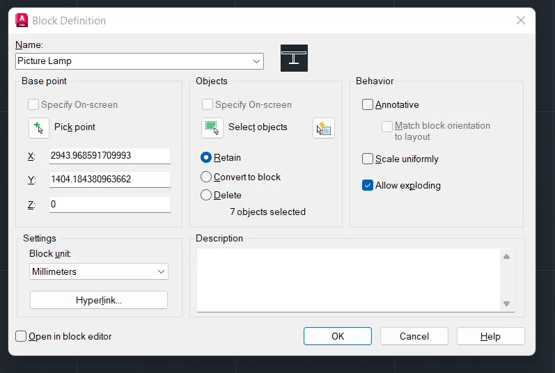
- Use Block command and Name the Block as Picture Lamp.
- And pick the base point and select the whole object.
- The Picture Lamp is created.
- Create a Table using Line Command and Use Insert command to insert the created Blocks.
- Use MText command for the Name of the Blocks.
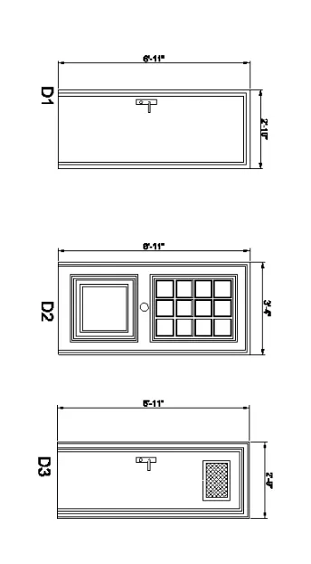
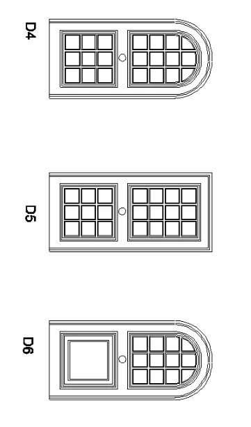
4. Create the door type for residential building as a block. Save the name of the blocks as type. Use given dimensions or assume dimensions as per industry standards.
AIM:
To Create the door type for residential building as a block. Save the name of the blocks as type.
PROCEDURE:
- Open AutoCAD Software.
- Use Unit Command and Set unit as Engineering and Inches.
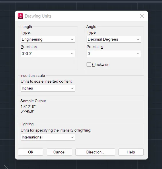
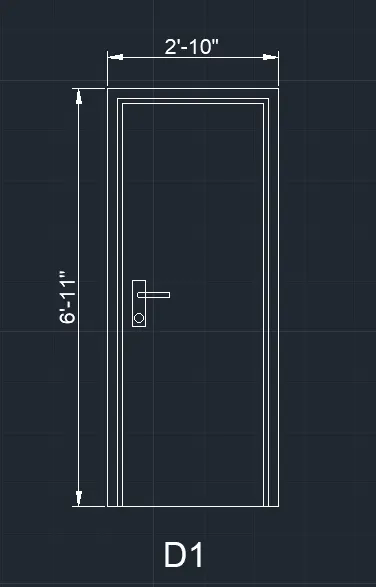
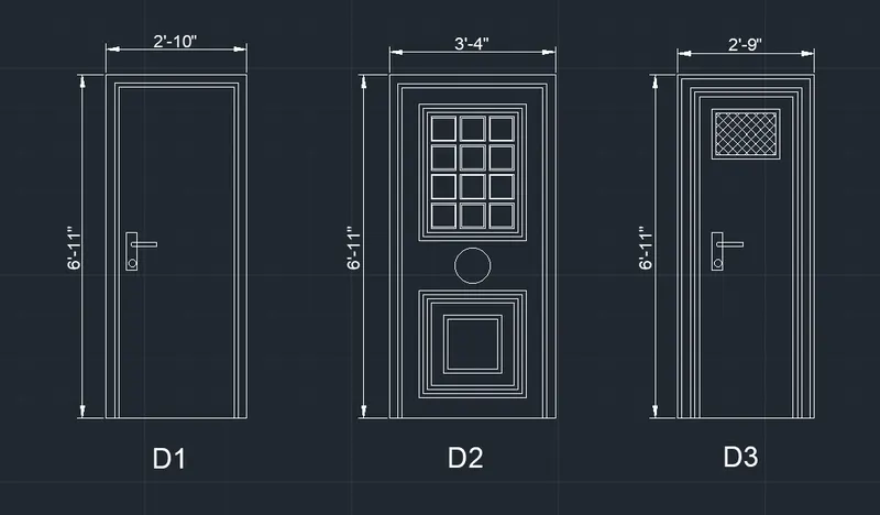
- Use Line command and Offset to create a Outline of the Door dimension as 2'10" X 6'11". And use Rec and Circle for the lock of the door. Use Dim Linear for the Dimention. And use MText for the Text.
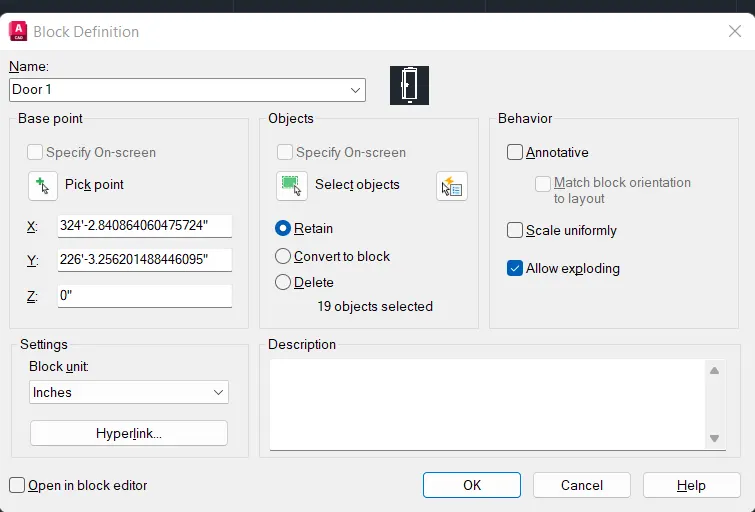
- Use Block Command and Name the Block as Door 1 and Pick the base point and select the Drawing and the Door 1 is Created.
- Use Line command and create a door outline as dimension of 3'4"X6'11".
- Then use Offset command for the Inter lines of the door and designs of the door.
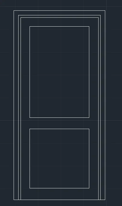
- Use Offset and Fillet command for the design of the door.
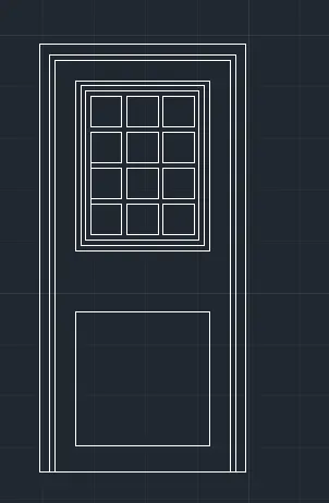
- Use Offset and Circle for the Design of the door.
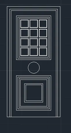
- Use Dim Linear for the dimension. And MText for the Text.
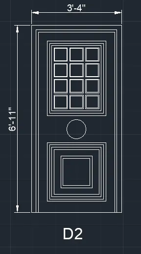
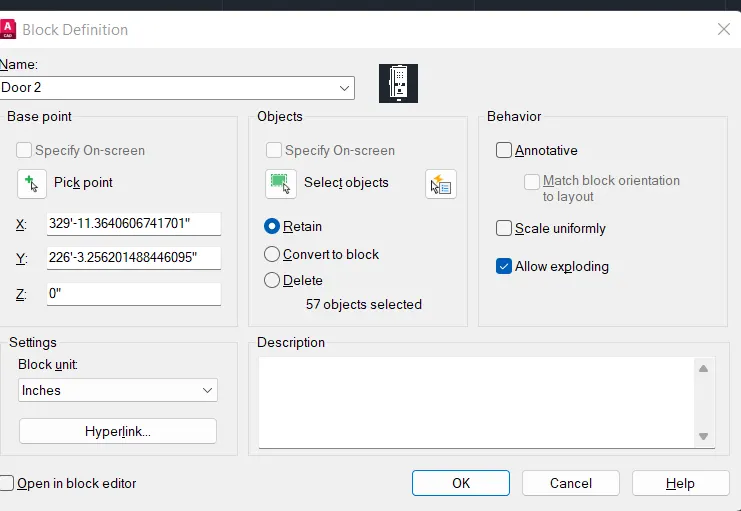
- Use Block Command and Name the Block as Door 2 and Pick the base point and select the object and D2 Block is created.
- Use Line, Offset, Rec, Circle and Hatch command for the Door 3.
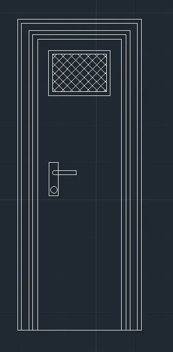
- Use Dim Linear for the dimension. And MText for the text.
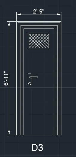
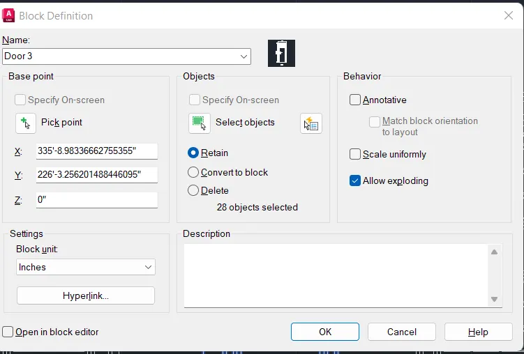
- Use Block command and name the block as Door 3 and Pick the base point and Select the object and the door 3 is Created.
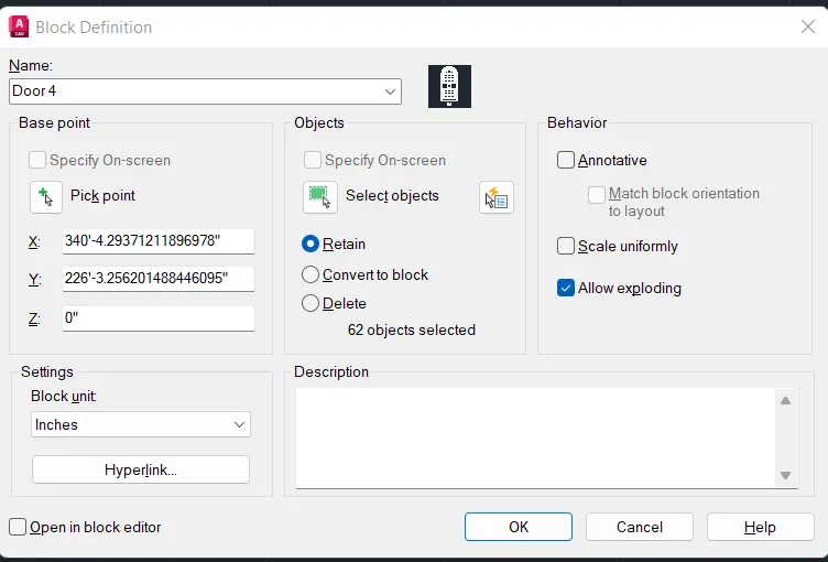
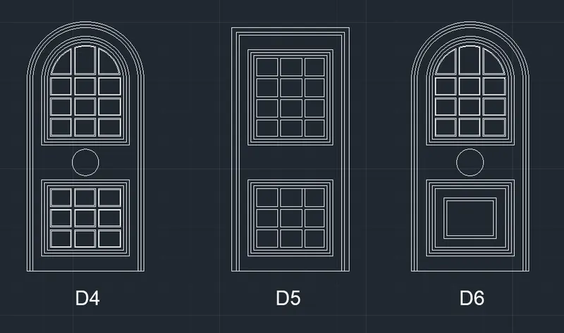
- Use Line, Offset, Arc, Fillet and Trim to create the D4. Use MText command for the text.
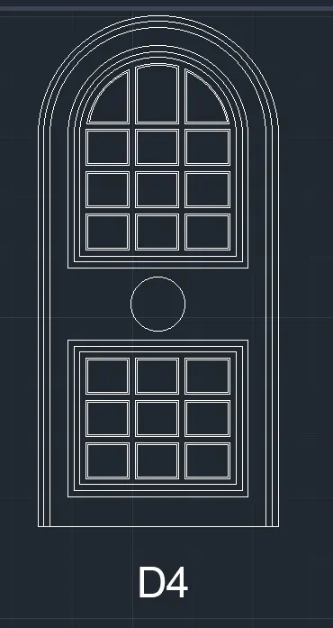
- Use Block command and Name the Block as Door 4 and pick the base point and select the object to create the block D4.
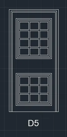
- Use Line, Offset, Fillet and Trim command for the Door 5. Use MText command for the Text.
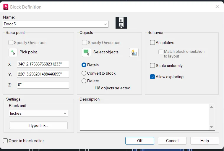
- Use Block Command and name the block as Door 5 and pick the base point and select the object and the Block is created.
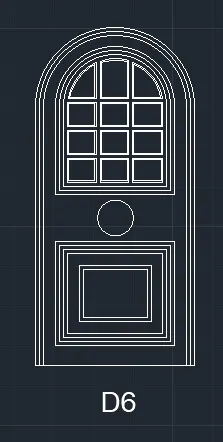
- Use Line, Offset, Arc, Fillet, Circle and Trim to create the D4. Use MText command for the text.
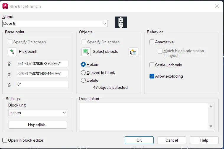
- Use Block Command and name the block as Door 6 and pick the base point and select the object and the Block is created.
RESULT:
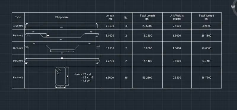
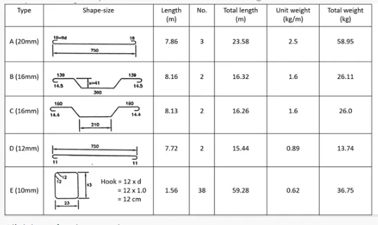
5. Create each shape as a block as shown in the Figure. Save the block and insert them on the table as shown in the Figure.
AIM:
TO create shape as a block as shown in the Figure. Save the block and insert them on the table as shown in the Figure.
PROCEDURE:
- Open AutoCAD Software.
- Use Unit command and set unit as "Decimal" and "Millimeters"
- Use Line command and create a line of length 750mm.
- Use circle command and draw Circle of 9 Dia.
- Then use trim command to create a Half circle which shown in the figure.

- Use Dim lin for the dimension.
- And use Text for the Letters and Texts.
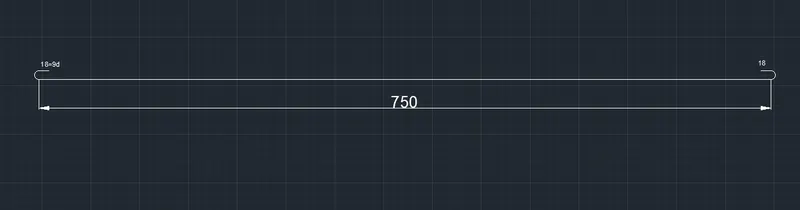
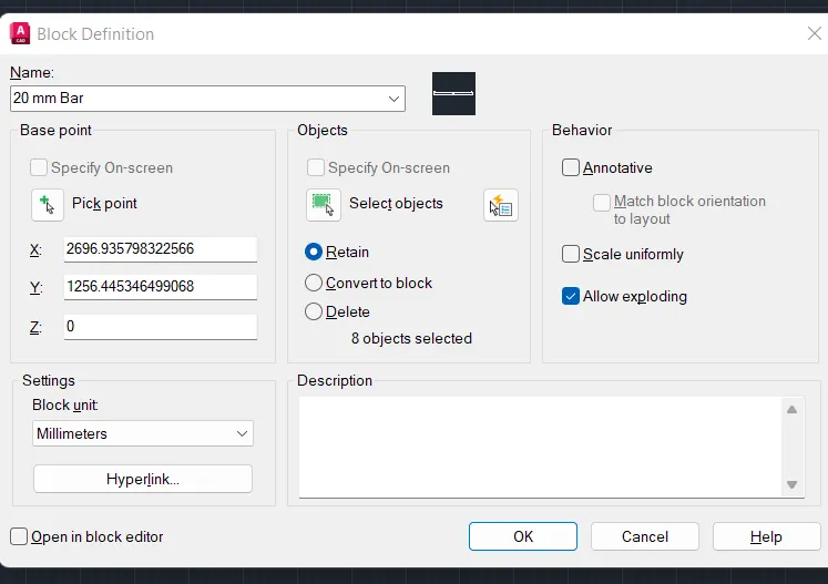
- Use Block command and Name the Block as 20mm Bar and pick the base point and select the whole object and enter. The bar diagram is created as a Block.
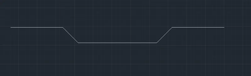
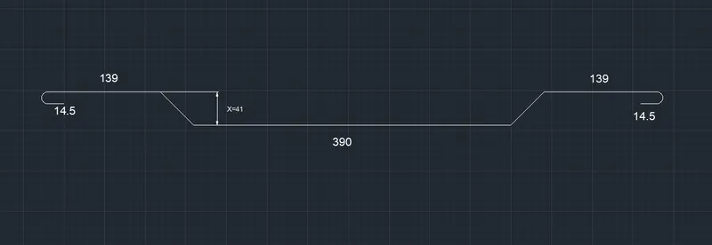
- Use line command and create a line of 390mm length and create an inclined line of 41mm of 45 degree angle.
- Then create line 139mm each side length.
- Use Circle and trim command to create the arc shaped part.
- Use Dim aligned for the dimension.
- Use MText for the Numbers.
- Use Block command and Name the Block as 16mm Bar and pick the base point and select the whole object and enter. The bar diagram is created as a Block.
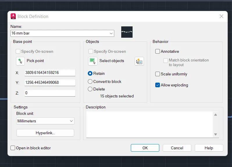
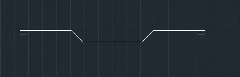
- Use line command and create a line of 210mm length and create an inclined line of 45 degree angle.
- Then create line 180mm each side length.
- Use Circle and trim command to create the arc shaped part.
- Use Dim Lin for the dimension.
- Use MText for the Numbers.
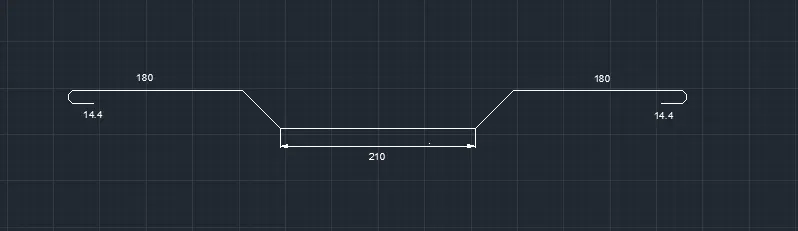
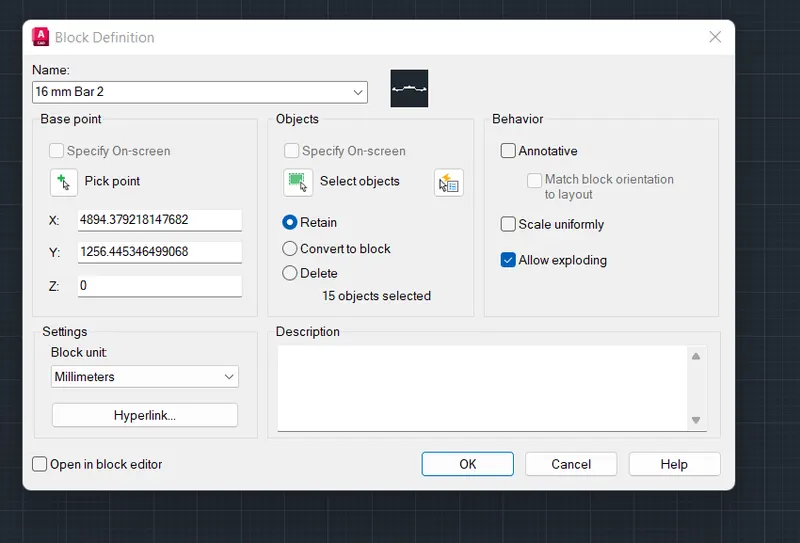
- Use Block command and Name the Block as 16mm Bar 2 and pick the base point and select the whole object and enter. The bar diagram is created as a Block.
- Use Line command and create a line of length 750mm.
- Use circle command and draw Circle of 11mm Dia.
- Then use trim command to create a Half circle which shown in the figure.
- Use Dim Lin for the dimension.
- Use MText for the Numbers.
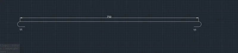
- Use Block command and Name the Block as 12mm Bar and pick the base point and select the whole object and enter. The bar diagram is created as a Block.
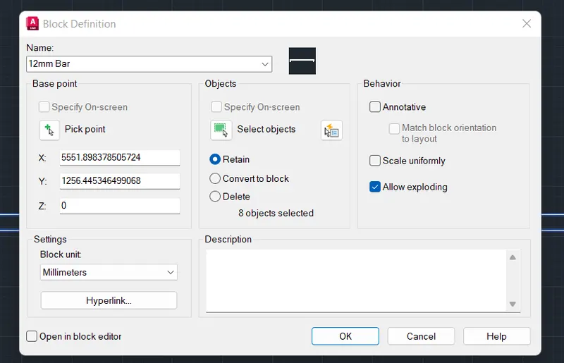
- Use Line command and create a Rectangle of 23mm X 43 mm.
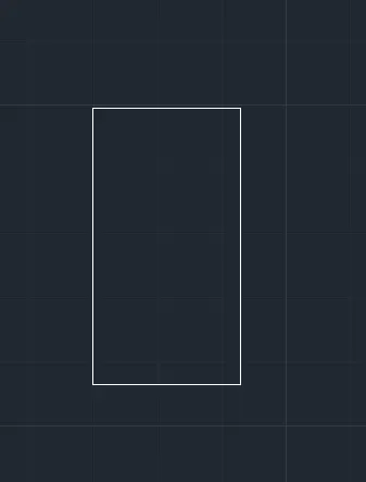
- Use Fillet command and create 5mm Arc shape in the four corners of the rectangle.
- Use Dim Lin for the dimensions.
- Use MText for the Texts.
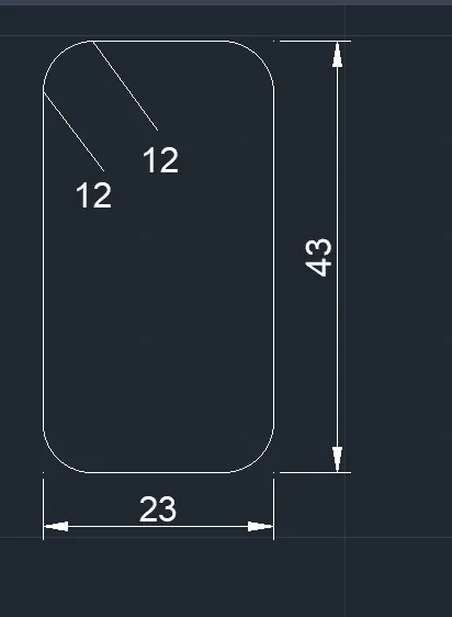
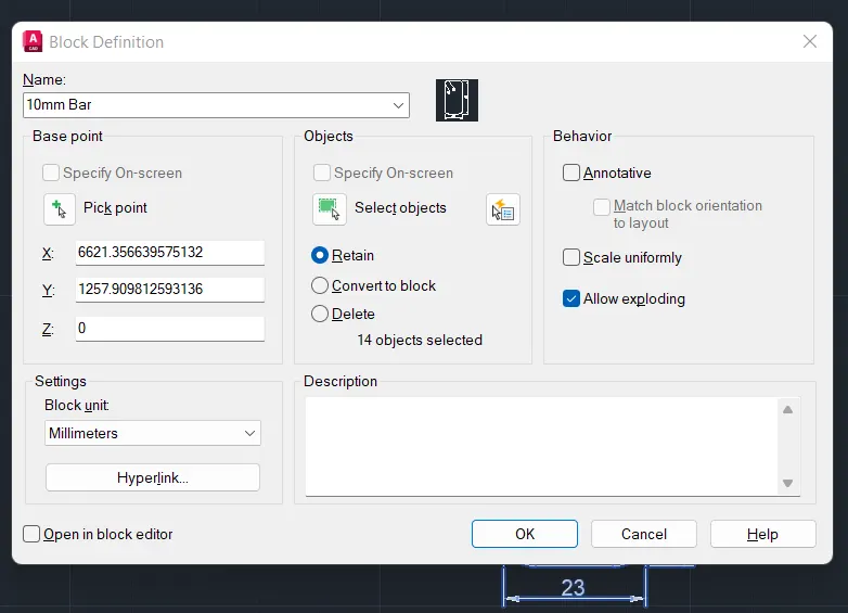
- Use Block command and Name the Block as 10mm Bar and pick the base point and select the whole object and enter. The bar diagram is created as a Block.
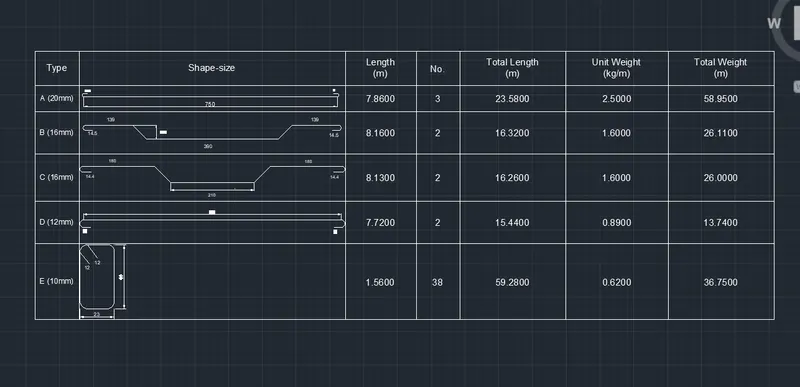
- Use Table command and create a table with 7 Column and 6 Rows.
- Then use Field in the table edit for the texts in the table.
- Use Block in the Table edit to insert the created Blocks.
- Then Align the Tables.
RESULT: