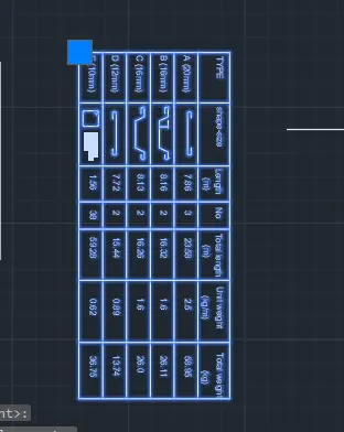
Creating Bar Bending schedule, Different Door types, and Creation of standard drawing templates using AutoCad
1.
Aim: To draw a given table schdule using autocad.
procedure: The following steps should be followed as a procedure to draw a given section table using autocad
- To draw the given section table in autocad, the following steps should be followed as a procedure. At first open the AutoCAD and set dimensions that the dimensions are in feets and inches.
- Then enter the Line command in AutoCAD and after that enter the first point of the given diagram as that line should be started at the point in the coordinate system.
- Draw a rectangle using the autocad command enter the dimensions as per the given requirement as per the table.
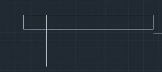
- Draw the outer dimensions given by the table by using line command in autocad ie draw the lines and draw the inner and outer lines by using the autocad command.
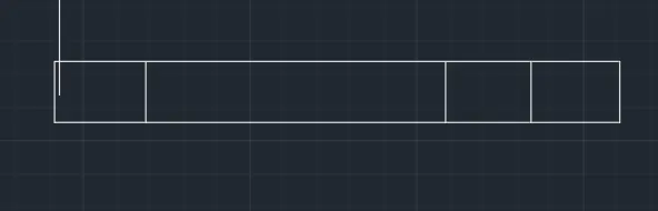
- Draw the outer dimensions given by the table by using line command in autocad ie draw the lines and draw the inner and outer lines by using the autocad command.
- by using the multi text command in auocad by selecting the multi text command then using the settings option we can get the size of the text given.
- draw the bottom line and the required lines by using the line command in the autocad then trim the extra lines as the required table.
- rotate the text which has been given as per the table and then make sure that the text settings which has been make as per the table settings and make sure that the text heatings is in bold in the settings os annative in the autocad.
- draw the bottom line and the required lines by using the line command in the autocad then trim the extra lines as the required table
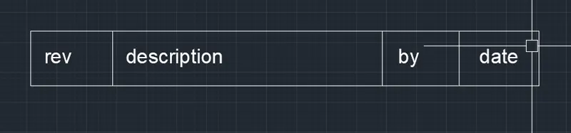
- draw the lines and the required lines by using the line command in the autocad then trim the extra lines as the required table that has been present in the table by using the line command or offset of the lines which has been present the lines is drawn and the extra lines which has been present is trim using the trim command in autocad then we get required lines in the table as shown in the figure below.
- and by using the multitext command or by copying the text which has been present in the another table the header text has been written or edited and edit the text as per the required and paste it on the row which has been present and edit the text and place the texting height as per the required table as shown in the figure below.
- draw the bottom line and the required lines by using the line command in the autocad then trim the extra lines as the required table.
- rotate the text which has been given as per the table and then make sure that the text settings which has been make as per the table settings and make sure that the text heatings is in bold in the settings os annative in the autocad.
- draw the bottom line and the required lines by using the line command in the autocad then trim the extra lines as the required table
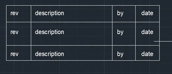
- and next by using the rectangle command in autocad draw a rectangle in the fourth cloumn and then give the dimensions as per the table and the size of the column as per the table and then make it offset of that rectangle to make it offset and then offset dimensions is taken as per the table and make the lines by using the line command and then copy all the circles and then make sure that copy that lines in the required places as per the table.
- and draw the remaing circles by using the line command in the autocad and then copy the lines and place it as per the table.
- and by using the multitext command or by copying the text which has been present in the another column the header text has been written or edited and edit the text as per the required and paste it on the row which has been present and edit the text and place the texting height as per the required table as shown in the figure below.
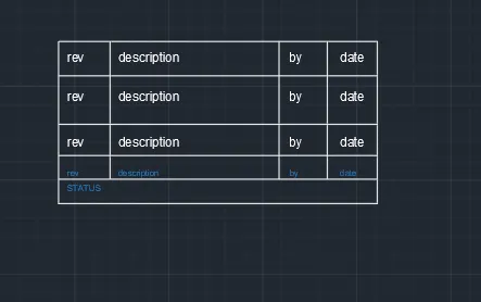
- next by using the rectangle command in autocad draw a rectangle in the fourth cloumn and then give the dimensions as per the table and the size of the column as per the table and then make it offset of that rectangle to make it offset and then offset dimensions is taken as per the table and make the circles by using the circle command and then copy all the lines and then make sure that copy that circles in the required places as per the table.
- and draw the remaing lines by using the line command in the autocad and then copy the lines and place it as per the table.
- and by using the multitext command or by copying the text which has been present in the another column the header text has been written or edited and edit the text as per the required and paste it on the row which has been present and edit the text and place the texting height as per the required table as shown in the figure below.
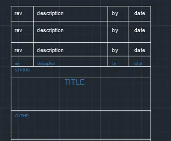
- next by using the rectangle command in autocad draw a rectangle in the fourth cloumn and then give the dimensions as per the table and the size of the column as per the table and then make it offset of that rectangle to make it offset and then offset dimensions is taken as per the table and make the circles by using the circle command and then copy all the circles and then make sure that copy that circles in the required places as per the table.
- and by using the multitext command or by copying the text which has been present in the another column the header text has been written or edited and edit the text as per the required and paste it on the row which has been present and edit the text and place the texting height as per the required table as shown in the figure below.
- draw and complete the table by using the command and then edit the tables by using multi text commands as shown in figure below.
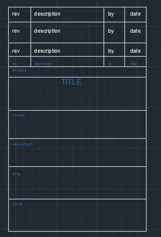
- next by using the rectangle command in autocad draw a rectangle in the fourth cloumn and then give the dimensions as per the table and the size of the column as per the table and then make it offset of that rectangle to make it offset and then offset dimensions is taken as per the table and make the circles by using the circle command and then copy all the circles and then make sure that copy that circles in the required places as per the table.
- and by using the multitext command or by copying the text which has been present in the another column the header text has been written or edited and edit the text as per the required and paste it on the row which has been present and edit the text and place the texting height as per the required table as shown in the figure below.
- draw and complete the table by using the command and then edit the tables by using multi text commands as shown in figure below.
- next by using the rectangle command in autocad draw a rectangle in the fourth cloumn and then give the dimensions as per the table and the size of the column as per the table and then make it offset of that rectangle to make it offset and then offset dimensions is taken as per the table and make the circles by using the circle command and then copy all the lines and then make sure that copy that circles in the required places as per the table.
- and draw the remaing lines by using the line command in the autocad and then copy the lines and place it as per the table.
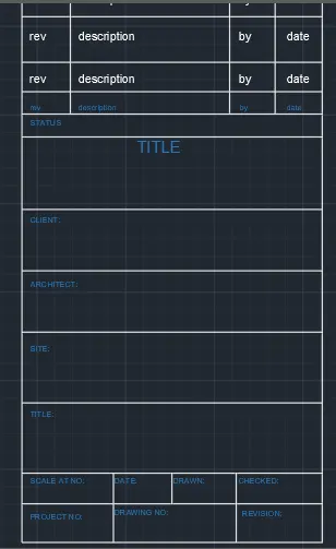
- To make the table as a single block then select the block option and create the block to create the block select on create block on view option and then for creating a block we have to pick the point ie the reference point and then select the lines or the objects which has to make block and then if we want to make annotative make annottive and then press ok.
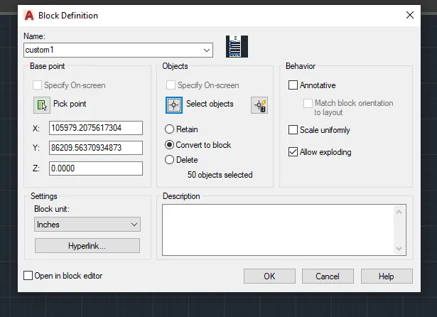
- here to create block click on create block option and create the block name in the block name option then pick up the reference point and then slect the texts and lines which have to make block and then press ok to crate the block.
- Now, you need to tell AutoCAD what the insertion point should be. In other words, when you place the block, the point about which the block appears at your cursor Click the Select Objects button and select the objects you want to be stored in the block.
b)
Aim: To draw a given table schdule using autocad.
procedure: The following steps should be followed as a procedure to draw a given section table using autocad
- To draw the given section table in autocad, the following steps should be followed as a procedure. At first open the AutoCAD and set dimensions that the dimensions are in feets and inches.
- Then enter the Line command in AutoCAD and after that enter the first point of the given diagram as that line should be started at the point in the coordinate system.
- Draw a rectangle using the autocad command enter the dimensions as per the given requirement as per the table.
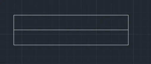
- Draw the outer dimensions given by the table by using line command in autocad ie draw the lines and draw the inner and outer lines by using the autocad command.
- by using the multi text command in auocad by selecting the multi text command then using the settings option we can get the size of the text given.
- draw the bottom line and the required lines by using the line command in the autocad then trim the extra lines as the required table.
- rotate the text which has been given as per the table and then make sure that the text settings which has been make as per the table settings and make sure that the text heatings is in bold in the settings os annative in the autocad.
- draw the bottom line and the required lines by using the line command in the autocad then trim the extra lines as the required table
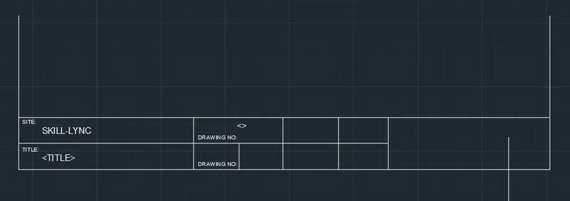
- Draw the outer dimensions given by the table by using line command in autocad ie draw the lines and draw the inner and outer lines by using the autocad command.
- by using the multi text command in auocad by selecting the multi text command then using the settings option we can get the size of the text given.
- draw the bottom line and the required lines by using the line command in the autocad then trim the extra lines as the required table.
- rotate the text which has been given as per the table and then make sure that the text settings which has been make as per the table settings and make sure that the text heatings is in bold in the settings os annative in the autocad.
- draw the bottom line and the required lines by using the line command in the autocad then trim the extra lines as the required table
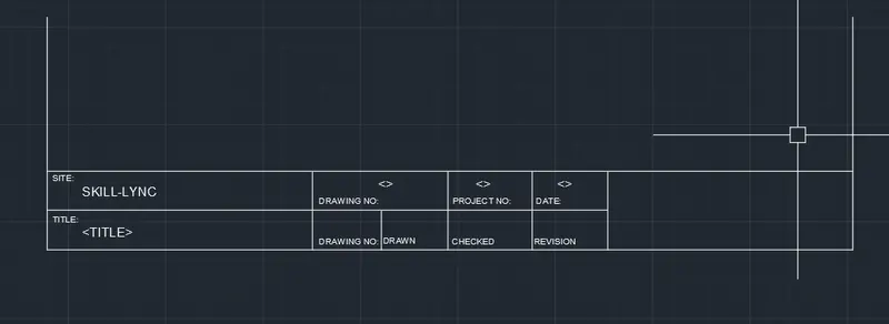
- draw the lines and the required lines by using the line command in the autocad then trim the extra lines as the required table that has been present in the table by using the line command or offset of the lines which has been present the lines is drawn and the extra lines which has been present is trim using the trim command in autocad then we get required lines in the table as shown in the figure below.
- and by using the multitext command or by copying the text which has been present in the another table the header text has been written or edited and edit the text as per the required and paste it on the row which has been present and edit the text and place the texting height as per the required table as shown in the figure below.
- draw the bottom line and the required lines by using the line command in the autocad then trim the extra lines as the required table.
- rotate the text which has been given as per the table and then make sure that the text settings which has been make as per the table settings and make sure that the text heatings is in bold in the settings os annative in the autocad.
- draw the bottom line and the required lines by using the line command in the autocad then trim the extra lines as the required table
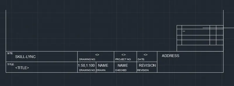
- next by using the rectangle command in autocad draw a rectangle in the fourth cloumn and then give the dimensions as per the table and the size of the column as per the table and then make it offset of that rectangle to make it offset and then offset dimensions is taken as per the table and make the circles by using the circle command and then copy all the circles and then make sure that copy that circles in the required places as per the table.
- and by using the multitext command or by copying the text which has been present in the another column the header text has been written or edited and edit the text as per the required and paste it on the row which has been present and edit the text and place the texting height as per the required table as shown in the figure below.
- draw and complete the table by using the command and then edit the tables by using multi text commands as shown in figure below.
- next by using the rectangle command in autocad draw a rectangle in the fourth cloumn and then give the dimensions as per the table and the size of the column as per the table and then make it offset of that rectangle to make it offset and then offset dimensions is taken as per the table and make the circles by using the circle command and then copy all the lines and then make sure that copy that circles in the required places as per the table.
- and draw the remaing lines by using the line command in the autocad and then copy the lines and place it as per the table.
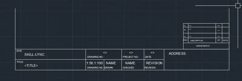
- To make the table as a single block then select the block option and create the block to create the block select on create block on view option and then for creating a block we have to pick the point ie the reference point and then select the lines or the objects which has to make block and then if we want to make annotative make annottive and then press ok.
- here to create block click on create block option and create the block name in the block name option then pick up the reference point and then slect the texts and lines which have to make block and then press ok to crate the block.
- Now, you need to tell AutoCAD what the insertion point should be. In other words, when you place the block, the point about which the block appears at your cursor Click the Select Objects button and select the objects you want to be stored in the block.
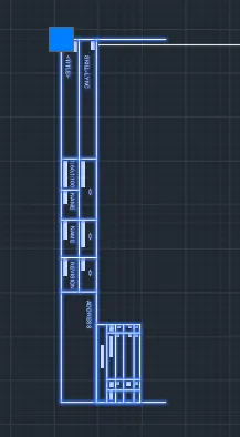
- To make the table as a single block then select the block option and create the block to create the block select on create block on view option and then for creating a block we have to pick the point ie the reference point and then select the lines or the objects which has to make block and then if we want to make annotative make annottive and then press ok.
- here to create block click on create block option and create the block name in the block name option then pick up the reference point and then slect the texts and lines which have to make block and then press ok to crate the block.
- Now, you need to tell AutoCAD what the insertion point should be. In other words, when you place the block, the point about which the block appears at your cursor Click the Select Objects button and select the objects you want to be stored in the block.
2.
Aim: To draw a given doors in the given floor plan using block schdule using autocad.
procedure: The following steps should be followed as a procedure to draw a given section doors in the given floor plan using block using autocad
- To draw the given section doors in the given floor plan using block in autocad, the following steps should be followed as a procedure. At first open the AutoCAD and set dimensions that the dimensions are in feets and inches.
- Then enter the Line command in AutoCAD and after that enter the first point of the given diagram as that line should be started at the point in the coordinate system.
- Draw a rectangle using the autocad command enter the dimensions as per the given requirement as per the table.
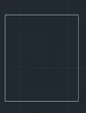
- Draw the outer dimensions given by the door by using line command in autocad ie draw the lines and draw the inner and outer lines by using the autocad command.
- by using the multi text command in auocad by selecting the multi text command then using the settings option we can get the size of the text given.
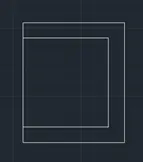
- Draw the outer dimensions given by the door by using line command in autocad ie draw the lines and draw the inner and outer lines by using the autocad command.
- by using the multi text command in auocad by selecting the multi text command then using the settings option we can get the size of the text given.
- draw the bottom line and the required lines by using the line command in the autocad then trim the extra lines as the required door.
- rotate the text which has been given as per the table and then make sure that the text settings which has been make as per the table settings and make sure that the text heatings is in bold in the settings os annative in the autocad.
- draw the bottom line and the required lines by using the line command in the autocad then trim the extra lines as the required door.

- Draw the outer dimensions given by the door by using line command in autocad ie draw the lines and draw the inner and outer lines by using the autocad command.
- by using the multi text command in auocad by selecting the multi text command then using the settings option we can get the size of the text given.
- draw the bottom line and the required lines by using the line command in the autocad then trim the extra lines as the required door.
- rotate the text which has been given as per the table and then make sure that the text settings which has been make as per the table settings and make sure that the text heatings is in bold in the settings os annative in the autocad.
- draw the bottom line and the required lines by using the line command in the autocad then trim the extra lines as the required door
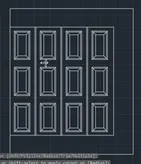
- To make the door as a single block then select the block option and create the block to create the block select on create block on view option and then for creating a block we have to pick the point ie the reference point and then select the lines or the objects which has to make block and then if we want to make annotative make annottive and then press ok.
- here to create block click on create block option and create the block name in the block name option then pick up the reference point and then slect the texts and lines which have to make block and then press ok to crate the block.
- Now, you need to tell AutoCAD what the insertion point should be. In other words, when you place the block, the point about which the block appears at your cursor Click the Select Objects button and select the objects you want to be stored in the block.
- To make the table as a single block then select the block option and create the block to create the block select on create block on view option and then for creating a block we have to pick the point ie the reference point and then select the lines or the objects which has to make block and then if we want to make annotative make annottive and then press ok.
- here to create block click on create block option and create the block name in the block name option then pick up the reference point and then slect the texts and lines which have to make block and then press ok to crate the block.
- Now, you need to tell AutoCAD what the insertion point should be. In other words, when you place the block, the point about which the block appears at your cursor Click the Select Objects button and select the objects you want to be stored in the block.
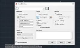
- To make the door as a single block then select the block option and create the block to create the block select on create block on view option and then for creating a block we have to pick the point ie the reference point and then select the lines or the objects which has to make block and then if we want to make annotative make annottive and then press ok.
- here to create block click on create block option and create the block name in the block name option then pick up the reference point and then slect the texts and lines which have to make block and then press ok to crate the block.
- Now, you need to tell AutoCAD what the insertion point should be. In other words, when you place the block, the point about which the block appears at your cursor Click the Select Objects button and select the objects you want to be stored in the block.
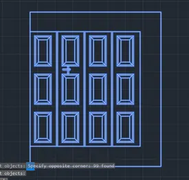
- Draw the outer dimensions given by the door by using line command in autocad ie draw the lines and draw the inner and outer lines by using the autocad command.
- by using the multi text command in auocad by selecting the multi text command then using the settings option we can get the size of the text given.
- Draw the outer dimensions given by the door by using line command in autocad ie draw the lines and draw the inner and outer lines by using the autocad command.
- by using the multi text command in auocad by selecting the multi text command then using the settings option we can get the size of the text given.
- draw the bottom line and the required lines by using the line command in the autocad then trim the extra lines as the required door.
- rotate the text which has been given as per the table and then make sure that the text settings which has been make as per the table settings and make sure that the text heatings is in bold in the settings os annative in the autocad.
- draw the bottom line and the required lines by using the line command in the autocad then trim the extra lines as the required door.
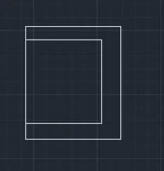
- draw the lines and the required lines by using the line command in the autocad then trim the extra lines as the required table that has been present in the table by using the line command or offset of the lines which has been present the lines is drawn and the extra lines which has been present is trim using the trim command in autocad then we get required lines in the table as shown in the figure below.
- and by using the multitext command or by copying the text which has been present in the another table the header text has been written or edited and edit the text as per the required and paste it on the row which has been present and edit the text and place the texting height as per the required table as shown in the figure below.
- draw the bottom line and the required lines by using the line command in the autocad then trim the extra lines as the required table.
- rotate the text which has been given as per the table and then make sure that the text settings which has been make as per the table settings and make sure that the text heatings is in bold in the settings os annative in the autocad.
- draw the bottom line and the required lines by using the line command in the autocad then trim the extra lines as the required table
- To make the door as a single block then select the block option and create the block to create the block select on create block on view option and then for creating a block we have to pick the point ie the reference point and then select the lines or the objects which has to make block and then if we want to make annotative make annottive and then press ok.
- here to create block click on create block option and create the block name in the block name option then pick up the reference point and then slect the texts and lines which have to make block and then press ok to crate the block.
- Now, you need to tell AutoCAD what the insertion point should be. In other words, when you place the block, the point about which the block appears at your cursor Click the Select Objects button and select the objects you want to be stored in the block.
- To make the table as a single block then select the block option and create the block to create the block select on create block on view option and then for creating a block we have to pick the point ie the reference point and then select the lines or the objects which has to make block and then if we want to make annotative make annottive and then press ok.
- here to create block click on create block option and create the block name in the block name option then pick up the reference point and then slect the texts and lines which have to make block and then press ok to crate the block.
- Now, you need to tell AutoCAD what the insertion point should be. In other words, when you place the block, the point about which the block appears at your cursor Click the Select Objects button and select the objects you want to be stored in the block.
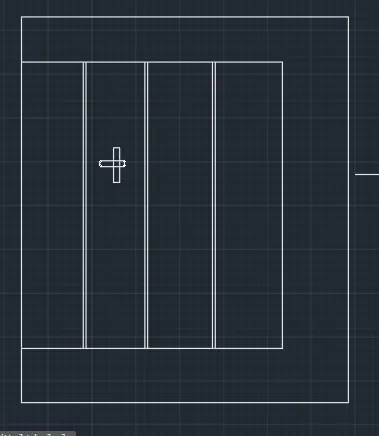
3.
Aim: To draw a given table schdule using autocad.
procedure: The following steps should be followed as a procedure to draw a given section table using autocad
- To draw the given section table in autocad, the following steps should be followed as a procedure. At first open the AutoCAD and set dimensions that the dimensions are in feets and inches.
- Then enter the Line command in AutoCAD and after that enter the first point of the given diagram as that line should be started at the point in the coordinate system.
- Draw a rectangle using the autocad command enter the dimensions as per the given requirement as per the table.
- Draw the given diagrams as per the taken measurements and then make it as a block.
- To make the table as a single block then select the block option and create the block to create the block select on create block on view option and then for creating a block we have to pick the point ie the reference point and then select the lines or the objects which has to make block and then if we want to make annotative make annottive and then press ok.
- here to create block click on create block option and create the block name in the block name option then pick up the reference point and then slect the texts and lines which have to make block and then press ok to crate the block.
- Now, you need to tell AutoCAD what the insertion point should be. In other words, when you place the block, the point about which the block appears at your cursor Click the Select Objects button and select the objects you want to be stored in the block.

- Draw the given diagrams as per the taken measurements and then make it as a block.
- To make the table as a single block then select the block option and create the block to create the block select on create block on view option and then for creating a block we have to pick the point ie the reference point and then select the lines or the objects which has to make block and then if we want to make annotative make annottive and then press ok.
- here to create block click on create block option and create the block name in the block name option then pick up the reference point and then slect the texts and lines which have to make block and then press ok to crate the block.
- Now, you need to tell AutoCAD what the insertion point should be. In other words, when you place the block, the point about which the block appears at your cursor Click the Select Objects button and select the objects you want to be stored in the block.

- Draw the given diagrams as per the taken measurements and then make it as a block.
- To make the table as a single block then select the block option and create the block to create the block select on create block on view option and then for creating a block we have to pick the point ie the reference point and then select the lines or the objects which has to make block and then if we want to make annotative make annottive and then press ok.
- here to create block click on create block option and create the block name in the block name option then pick up the reference point and then slect the texts and lines which have to make block and then press ok to crate the block.
- Now, you need to tell AutoCAD what the insertion point should be. In other words, when you place the block, the point about which the block appears at your cursor Click the Select Objects button and select the objects you want to be stored in the block.

- Draw the given diagrams as per the taken measurements and then make it as a block.
- To make the table as a single block then select the block option and create the block to create the block select on create block on view option and then for creating a block we have to pick the point ie the reference point and then select the lines or the objects which has to make block and then if we want to make annotative make annottive and then press ok.
- here to create block click on create block option and create the block name in the block name option then pick up the reference point and then slect the texts and lines which have to make block and then press ok to crate the block.
- Now, you need to tell AutoCAD what the insertion point should be. In other words, when you place the block, the point about which the block appears at your cursor Click the Select Objects button and select the objects you want to be stored in the block

- Draw the given diagrams as per the taken measurements and then make it as a block.
- To make the table as a single block then select the block option and create the block to create the block select on create block on view option and then for creating a block we have to pick the point ie the reference point and then select the lines or the objects which has to make block and then if we want to make annotative make annottive and then press ok.
- here to create block click on create block option and create the block name in the block name option then pick up the reference point and then slect the texts and lines which have to make block and then press ok to crate the block.
- Now, you need to tell AutoCAD what the insertion point should be. In other words, when you place the block, the point about which the block appears at your cursor Click the Select Objects button and select the objects you want to be stored in the block

- Draw the given diagrams as per the taken measurements and then make it as a block.
- To make the table as a single block then select the block option and create the block to create the block select on create block on view option and then for creating a block we have to pick the point ie the reference point and then select the lines or the objects which has to make block and then if we want to make annotative make annottive and then press ok.
- here to create block click on create block option and create the block name in the block name option then pick up the reference point and then slect the texts and lines which have to make block and then press ok to crate the block.
- Now, you need to tell AutoCAD what the insertion point should be. In other words, when you place the block, the point about which the block appears at your cursor Click the Select Objects button and select the objects you want to be stored in the block

- Draw the given diagrams as per the taken measurements and then make it as a block.
- To make the table as a single block then select the block option and create the block to create the block select on create block on view option and then for creating a block we have to pick the point ie the reference point and then select the lines or the objects which has to make block and then if we want to make annotative make annottive and then press ok.
- here to create block click on create block option and create the block name in the block name option then pick up the reference point and then slect the texts and lines which have to make block and then press ok to crate the block.
- Now, you need to tell AutoCAD what the insertion point should be. In other words, when you place the block, the point about which the block appears at your cursor Click the Select Objects button and select the objects you want to be stored in the block
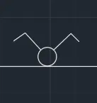
- Draw the given diagrams as per the taken measurements and then make it as a block.
- To make the table as a single block then select the block option and create the block to create the block select on create block on view option and then for creating a block we have to pick the point ie the reference point and then select the lines or the objects which has to make block and then if we want to make annotative make annottive and then press ok.
- here to create block click on create block option and create the block name in the block name option then pick up the reference point and then slect the texts and lines which have to make block and then press ok to crate the block.
- Now, you need to tell AutoCAD what the insertion point should be. In other words, when you place the block, the point about which the block appears at your cursor Click the Select Objects button and select the objects you want to be stored in the block

- Draw the given diagrams as per the taken measurements and then make it as a block.
- To make the table as a single block then select the block option and create the block to create the block select on create block on view option and then for creating a block we have to pick the point ie the reference point and then select the lines or the objects which has to make block and then if we want to make annotative make annottive and then press ok.
- here to create block click on create block option and create the block name in the block name option then pick up the reference point and then slect the texts and lines which have to make block and then press ok to crate the block.
- Now, you need to tell AutoCAD what the insertion point should be. In other words, when you place the block, the point about which the block appears at your cursor Click the Select Objects button and select the objects you want to be stored in the block

- Draw the given diagrams as per the taken measurements and then make it as a block.
- To make the table as a single block then select the block option and create the block to create the block select on create block on view option and then for creating a block we have to pick the point ie the reference point and then select the lines or the objects which has to make block and then if we want to make annotative make annottive and then press ok.
- here to create block click on create block option and create the block name in the block name option then pick up the reference point and then slect the texts and lines which have to make block and then press ok to crate the block.
- Now, you need to tell AutoCAD what the insertion point should be. In other words, when you place the block, the point about which the block appears at your cursor Click the Select Objects button and select the objects you want to be stored in the block

- Draw the given diagrams as per the taken measurements and then make it as a block.
- To make the table as a single block then select the block option and create the block to create the block select on create block on view option and then for creating a block we have to pick the point ie the reference point and then select the lines or the objects which has to make block and then if we want to make annotative make annottive and then press ok.
- here to create block click on create block option and create the block name in the block name option then pick up the reference point and then slect the texts and lines which have to make block and then press ok to crate the block.
- Now, you need to tell AutoCAD what the insertion point should be. In other words, when you place the block, the point about which the block appears at your cursor Click the Select Objects button and select the objects you want to be stored in the block

- Draw the given diagrams as per the taken measurements and then make it as a block.
- To make the table as a single block then select the block option and create the block to create the block select on create block on view option and then for creating a block we have to pick the point ie the reference point and then select the lines or the objects which has to make block and then if we want to make annotative make annottive and then press ok.
- here to create block click on create block option and create the block name in the block name option then pick up the reference point and then slect the texts and lines which have to make block and then press ok to crate the block.
- Now, you need to tell AutoCAD what the insertion point should be. In other words, when you place the block, the point about which the block appears at your cursor Click the Select Objects button and select the objects you want to be stored in the block

- Draw the given diagrams as per the taken measurements and then make it as a block.
- To make the table as a single block then select the block option and create the block to create the block select on create block on view option and then for creating a block we have to pick the point ie the reference point and then select the lines or the objects which has to make block and then if we want to make annotative make annottive and then press ok.
- here to create block click on create block option and create the block name in the block name option then pick up the reference point and then slect the texts and lines which have to make block and then press ok to crate the block.
- Now, you need to tell AutoCAD what the insertion point should be. In other words, when you place the block, the point about which the block appears at your cursor Click the Select Objects button and select the objects you want to be stored in the block

- Draw the given diagrams as per the taken measurements and then make it as a block.
- To make the table as a single block then select the block option and create the block to create the block select on create block on view option and then for creating a block we have to pick the point ie the reference point and then select the lines or the objects which has to make block and then if we want to make annotative make annottive and then press ok.
- here to create block click on create block option and create the block name in the block name option then pick up the reference point and then slect the texts and lines which have to make block and then press ok to crate the block.
- Now, you need to tell AutoCAD what the insertion point should be. In other words, when you place the block, the point about which the block appears at your cursor Click the Select Objects button and select the objects you want to be stored in the block
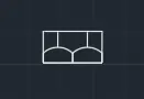
- Draw the given diagrams as per the taken measurements and then make it as a block.
- To make the table as a single block then select the block option and create the block to create the block select on create block on view option and then for creating a block we have to pick the point ie the reference point and then select the lines or the objects which has to make block and then if we want to make annotative make annottive and then press ok.
- here to create block click on create block option and create the block name in the block name option then pick up the reference point and then slect the texts and lines which have to make block and then press ok to crate the block.
- Now, you need to tell AutoCAD what the insertion point should be. In other words, when you place the block, the point about which the block appears at your cursor Click the Select Objects button and select the objects you want to be stored in the block

- Draw the given diagrams as per the taken measurements and then make it as a block.
- To make the table as a single block then select the block option and create the block to create the block select on create block on view option and then for creating a block we have to pick the point ie the reference point and then select the lines or the objects which has to make block and then if we want to make annotative make annottive and then press ok.
- here to create block click on create block option and create the block name in the block name option then pick up the reference point and then slect the texts and lines which have to make block and then press ok to crate the block.
- Now, you need to tell AutoCAD what the insertion point should be. In other words, when you place the block, the point about which the block appears at your cursor Click the Select Objects button and select the objects you want to be stored in the block
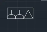
- Draw the given diagrams as per the taken measurements and then make it as a block.
- To make the table as a single block then select the block option and create the block to create the block select on create block on view option and then for creating a block we have to pick the point ie the reference point and then select the lines or the objects which has to make block and then if we want to make annotative make annottive and then press ok.
- here to create block click on create block option and create the block name in the block name option then pick up the reference point and then slect the texts and lines which have to make block and then press ok to crate the block.
- Now, you need to tell AutoCAD what the insertion point should be. In other words, when you place the block, the point about which the block appears at your cursor Click the Select Objects button and select the objects you want to be stored in the block

- Draw the given diagrams as per the taken measurements and then make it as a block.
- To make the table as a single block then select the block option and create the block to create the block select on create block on view option and then for creating a block we have to pick the point ie the reference point and then select the lines or the objects which has to make block and then if we want to make annotative make annottive and then press ok.
- here to create block click on create block option and create the block name in the block name option then pick up the reference point and then slect the texts and lines which have to make block and then press ok to crate the block.
- Now, you need to tell AutoCAD what the insertion point should be. In other words, when you place the block, the point about which the block appears at your cursor Click the Select Objects button and select the objects you want to be stored in the block

- Draw the given diagrams as per the taken measurements and then make it as a block.
- To make the table as a single block then select the block option and create the block to create the block select on create block on view option and then for creating a block we have to pick the point ie the reference point and then select the lines or the objects which has to make block and then if we want to make annotative make annottive and then press ok.
- here to create block click on create block option and create the block name in the block name option then pick up the reference point and then slect the texts and lines which have to make block and then press ok to crate the block.
- Now, you need to tell AutoCAD what the insertion point should be. In other words, when you place the block, the point about which the block appears at your cursor Click the Select Objects button and select the objects you want to be stored in the block

- Draw the given diagrams as per the taken measurements and then make it as a block.
- To make the table as a single block then select the block option and create the block to create the block select on create block on view option and then for creating a block we have to pick the point ie the reference point and then select the lines or the objects which has to make block and then if we want to make annotative make annottive and then press ok.
- here to create block click on create block option and create the block name in the block name option then pick up the reference point and then slect the texts and lines which have to make block and then press ok to crate the block.
- Now, you need to tell AutoCAD what the insertion point should be. In other words, when you place the block, the point about which the block appears at your cursor Click the Select Objects button and select the objects you want to be stored in the block

- Draw the given diagrams as per the taken measurements and then make it as a block.
- To make the table as a single block then select the block option and create the block to create the block select on create block on view option and then for creating a block we have to pick the point ie the reference point and then select the lines or the objects which has to make block and then if we want to make annotative make annottive and then press ok.
- here to create block click on create block option and create the block name in the block name option then pick up the reference point and then slect the texts and lines which have to make block and then press ok to crate the block.
- Now, you need to tell AutoCAD what the insertion point should be. In other words, when you place the block, the point about which the block appears at your cursor Click the Select Objects button and select the objects you want to be stored in the block

- Draw the given diagrams as per the taken measurements and then make it as a block.
- To make the table as a single block then select the block option and create the block to create the block select on create block on view option and then for creating a block we have to pick the point ie the reference point and then select the lines or the objects which has to make block and then if we want to make annotative make annottive and then press ok.
- here to create block click on create block option and create the block name in the block name option then pick up the reference point and then slect the texts and lines which have to make block and then press ok to crate the block.
- Now, you need to tell AutoCAD what the insertion point should be. In other words, when you place the block, the point about which the block appears at your cursor Click the Select Objects button and select the objects you want to be stored in the block

- draw the lines and the required lines by using the line command in the autocad then trim the extra lines as the required table that has been present in the table by using the line command or offset of the lines which has been present the lines is drawn and the extra lines which has been present is trim using the trim command in autocad then we get required lines in the table as shown in the figure below.
- and by using the multitext command or by copying the text which has been present in the another table the header text has been written or edited and edit the text as per the required and paste it on the row which has been present and edit the text and place the texting height as per the required table as shown in the figure below.
- draw the bottom line and the required lines by using the line command in the autocad then trim the extra lines as the required table.
- rotate the text which has been given as per the table and then make sure that the text settings which has been make as per the table settings and make sure that the text heatings is in bold in the settings os annative in the autocad.
- draw the bottom line and the required lines by using the line command in the autocad then trim the extra lines as the required table
- To make the door as a single block then select the block option and create the block to create the block select on create block on view option and then for creating a block we have to pick the point ie the reference point and then select the lines or the objects which has to make block and then if we want to make annotative make annottive and then press ok.
- here to create block click on create block option and create the block name in the block name option then pick up the reference point and then slect the texts and lines which have to make block and then press ok to crate the block.
- Now, you need to tell AutoCAD what the insertion point should be. In other words, when you place the block, the point about which the block appears at your cursor Click the Select Objects button and select the objects you want to be stored in the block.
- To make the table as a single block then select the block option and create the block to create the block select on create block on view option and then for creating a block we have to pick the point ie the reference point and then select the lines or the objects which has to make block and then if we want to make annotative make annottive and then press ok.
- here to create block click on create block option and create the block name in the block name option then pick up the reference point and then slect the texts and lines which have to make block and then press ok to crate the block.
- Now, you need to tell AutoCAD what the insertion point should be. In other words, when you place the block, the point about which the block appears at your cursor Click the Select Objects button and select the objects you want to be stored in the block.
4.
Aim: To draw a given doors in the given floor plan using block schdule using autocad.
procedure: The following steps should be followed as a procedure to draw a given section doors in the given floor plan using block using autocad
- To draw the given section doors in the given floor plan using block in autocad, the following steps should be followed as a procedure. At first open the AutoCAD and set dimensions that the dimensions are in feets and inches.
- Then enter the Line command in AutoCAD and after that enter the first point of the given diagram as that line should be started at the point in the coordinate system.
- Draw a rectangle using the autocad command enter the dimensions as per the given requirement as per the dimensions.

- Draw the outer dimensions given by the door by using line command in autocad ie draw the lines and draw the inner and outer lines by using the autocad command.
- by using the multi text command in auocad by selecting the multi text command then using the settings option we can get the size of the text given.
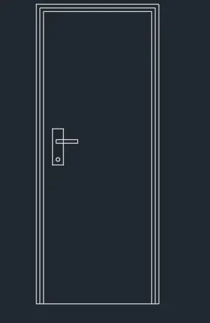
- Draw the outer dimensions given by the door by using line command in autocad ie draw the lines and draw the inner and outer lines by using the autocad command.
- by using the multi text command in auocad by selecting the multi text command then using the settings option we can get the size of the text given.
- draw the bottom line and the required lines by using the line command in the autocad then trim the extra lines as the required door.
- rotate the text which has been given as per the table and then make sure that the text settings which has been make as per the table settings and make sure that the text heatings is in bold in the settings os annative in the autocad.
- draw the bottom line and the required lines by using the line command in the autocad then trim the extra lines as the required door.
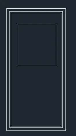
- To make the door as a single block then select the block option and create the block to create the block select on create block on view option and then for creating a block we have to pick the point ie the reference point and then select the lines or the objects which has to make block and then if we want to make annotative make annottive and then press ok.
- here to create block click on create block option and create the block name in the block name option then pick up the reference point and then slect the texts and lines which have to make block and then press ok to crate the block.
- Now, you need to tell AutoCAD what the insertion point should be. In other words, when you place the block, the point about which the block appears at your cursor Click the Select Objects button and select the objects you want to be stored in the block.
- To make the table as a single block then select the block option and create the block to create the block select on create block on view option and then for creating a block we have to pick the point ie the reference point and then select the lines or the objects which has to make block and then if we want to make annotative make annottive and then press ok.
- here to create block click on create block option and create the block name in the block name option then pick up the reference point and then slect the texts and lines which have to make block and then press ok to crate the block.
- Now, you need to tell AutoCAD what the insertion point should be. In other words, when you place the block, the point about which the block appears at your cursor Click the Select Objects button and select the objects you want to be stored in the block.
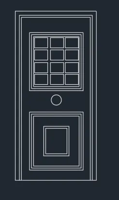
- To draw the given section doors in the given floor plan using block in autocad, the following steps should be followed as a procedure. At first open the AutoCAD and set dimensions that the dimensions are in feets and inches.
- Then enter the Line command in AutoCAD and after that enter the first point of the given diagram as that line should be started at the point in the coordinate system.
- Draw a rectangle using the autocad command enter the dimensions as per the given requirement as per the dimensions.
- To make the door as a single block then select the block option and create the block to create the block select on create block on view option and then for creating a block we have to pick the point ie the reference point and then select the lines or the objects which has to make block and then if we want to make annotative make annottive and then press ok.
- here to create block click on create block option and create the block name in the block name option then pick up the reference point and then slect the texts and lines which have to make block and then press ok to crate the block.
- Now, you need to tell AutoCAD what the insertion point should be. In other words, when you place the block, the point about which the block appears at your cursor Click the Select Objects button and select the objects you want to be stored in the block.
- To make the table as a single block then select the block option and create the block to create the block select on create block on view option and then for creating a block we have to pick the point ie the reference point and then select the lines or the objects which has to make block and then if we want to make annotative make annottive and then press ok.
- here to create block click on create block option and create the block name in the block name option then pick up the reference point and then slect the texts and lines which have to make block and then press ok to crate the block.
- Now, you need to tell AutoCAD what the insertion point should be. In other words, when you place the block, the point about which the block appears at your cursor Click the Select Objects button and select the objects you want to be stored in the block.
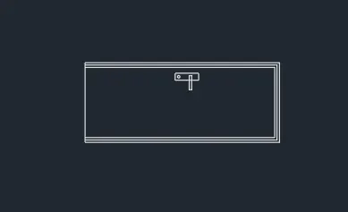
- Draw the outer dimensions given by the door by using line command in autocad ie draw the lines and draw the inner and outer lines by using the autocad command.
- by using the multi text command in auocad by selecting the multi text command then using the settings option we can get the size of the text given.
- draw the bottom line and the required lines by using the line command in the autocad then trim the extra lines as the required door.
- rotate the text which has been given as per the table and then make sure that the text settings which has been make as per the table settings and make sure that the text heatings is in bold in the settings os annative in the autocad.
- draw the bottom line and the required lines by using the line command in the autocad then trim the extra lines as the required door.
- To make the door as a single block then select the block option and create the block to create the block select on create block on view option and then for creating a block we have to pick the point ie the reference point and then select the lines or the objects which has to make block and then if we want to make annotative make annottive and then press ok.
- here to create block click on create block option and create the block name in the block name option then pick up the reference point and then slect the texts and lines which have to make block and then press ok to crate the block.
- Now, you need to tell AutoCAD what the insertion point should be. In other words, when you place the block, the point about which the block appears at your cursor Click the Select Objects button and select the objects you want to be stored in the block.
- To make the table as a single block then select the block option and create the block to create the block select on create block on view option and then for creating a block we have to pick the point ie the reference point and then select the lines or the objects which has to make block and then if we want to make annotative make annottive and then press ok.
- here to create block click on create block option and create the block name in the block name option then pick up the reference point and then slect the texts and lines which have to make block and then press ok to crate the block.
- Now, you need to tell AutoCAD what the insertion point should be. In other words, when you place the block, the point about which the block appears at your cursor Click the Select Objects button and select the objects you want to be stored in the block.
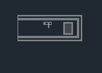
- Draw the outer dimensions given by the door by using line command in autocad ie draw the lines and draw the inner and outer lines by using the autocad command.
- by using the multi text command in auocad by selecting the multi text command then using the settings option we can get the size of the text given.
- draw the bottom line and the required lines by using the line command in the autocad then trim the extra lines as the required door.
- rotate the text which has been given as per the table and then make sure that the text settings which has been make as per the table settings and make sure that the text heatings is in bold in the settings os annative in the autocad.
- draw the bottom line and the required lines by using the line command in the autocad then trim the extra lines as the required door.
- make the door as a single block then select the block option and create the block to create the block select on create block on view option and then for creating a block we have to pick the point ie the reference point and then select the lines or the objects which has to make block and then if we want to make annotative make annottive and then press ok.
- here to create block click on create block option and create the block name in the block name option then pick up the reference point and then slect the texts and lines which have to make block and then press ok to crate the block.
- Now, you need to tell AutoCAD what the insertion point should be. In other words, when you place the block, the point about which the block appears at your cursor Click the Select Objects button and select the objects you want to be stored in the block.
- To make the table as a single block then select the block option and create the block to create the block select on create block on view option and then for creating a block we have to pick the point ie the reference point and then select the lines or the objects which has to make block and then if we want to make annotative make annottive and then press ok.
- here to create block click on create block option and create the block name in the block name option then pick up the reference point and then slect the texts and lines which have to make block and then press ok to crate the block.
- Now, you need to tell AutoCAD what the insertion point should be. In other words, when you place the block, the point about which the block appears at your cursor Click the Select Objects button and select the objects you want to be stored in the block.
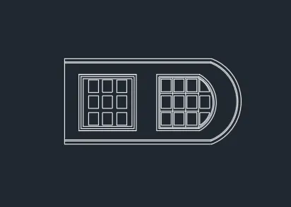
- Draw the outer dimensions given by the door by using line command in autocad ie draw the lines and draw the inner and outer lines by using the autocad command.
- by using the multi text command in auocad by selecting the multi text command then using the settings option we can get the size of the text given.
- draw the bottom line and the required lines by using the line command in the autocad then trim the extra lines as the required door.
- rotate the text which has been given as per the table and then make sure that the text settings which has been make as per the table settings and make sure that the text heatings is in bold in the settings os annative in the autocad.
- draw the bottom line and the required lines by using the line command in the autocad then trim the extra lines as the required door.
- make the door as a single block then select the block option and create the block to create the block select on create block on view option and then for creating a block we have to pick the point ie the reference point and then select the lines or the objects which has to make block and then if we want to make annotative make annottive and then press ok.
- here to create block click on create block option and create the block name in the block name option then pick up the reference point and then slect the texts and lines which have to make block and then press ok to crate the block.
- Now, you need to tell AutoCAD what the insertion point should be. In other words, when you place the block, the point about which the block appears at your cursor Click the Select Objects button and select the objects you want to be stored in the block.
- To make the table as a single block then select the block option and create the block to create the block select on create block on view option and then for creating a block we have to pick the point ie the reference point and then select the lines or the objects which has to make block and then if we want to make annotative make annottive and then press ok.
- here to create block click on create block option and create the block name in the block name option then pick up the reference point and then slect the texts and lines which have to make block and then press ok to crate the block.
- Now, you need to tell AutoCAD what the insertion point should be. In other words, when you place the block, the point about which the block appears at your cursor Click the Select Objects button and select the objects you want to be stored in the block.
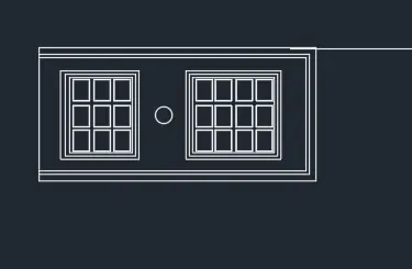
- Draw the outer dimensions given by the door by using line command in autocad ie draw the lines and draw the inner and outer lines by using the autocad command.
- by using the multi text command in auocad by selecting the multi text command then using the settings option we can get the size of the text given.
- draw the bottom line and the required lines by using the line command in the autocad then trim the extra lines as the required door.
- rotate the text which has been given as per the table and then make sure that the text settings which has been make as per the table settings and make sure that the text heatings is in bold in the settings os annative in the autocad.
- draw the bottom line and the required lines by using the line command in the autocad then trim the extra lines as the required door.
- make the door as a single block then select the block option and create the block to create the block select on create block on view option and then for creating a block we have to pick the point ie the reference point and then select the lines or the objects which has to make block and then if we want to make annotative make annottive and then press ok.
- here to create block click on create block option and create the block name in the block name option then pick up the reference point and then slect the texts and lines which have to make block and then press ok to crate the block.
- Now, you need to tell AutoCAD what the insertion point should be. In other words, when you place the block, the point about which the block appears at your cursor Click the Select Objects button and select the objects you want to be stored in the block.
- To make the table as a single block then select the block option and create the block to create the block select on create block on view option and then for creating a block we have to pick the point ie the reference point and then select the lines or the objects which has to make block and then if we want to make annotative make annottive and then press ok.
- here to create block click on create block option and create the block name in the block name option then pick up the reference point and then slect the texts and lines which have to make block and then press ok to crate the block.
- Now, you need to tell AutoCAD what the insertion point should be. In other words, when you place the block, the point about which the block appears at your cursor Click the Select Objects button and select the objects you want to be stored in the block.

5.
Aim: To draw a given table schdule using autocad.
procedure: The following steps should be followed as a procedure to draw a given section table using autocad
- To draw the given section table in autocad, the following steps should be followed as a procedure. At first open the AutoCAD and set dimensions that the dimensions are in feets and inches.
- Then enter the Line command in AutoCAD and after that enter the first point of the given diagram as that line should be started at the point in the coordinate system.
- Draw a rectangle using the autocad command enter the dimensions as per the given requirement as per the table.
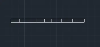
- Draw the outer dimensions given by the table by using line command in autocad ie draw the lines and draw the inner and outer lines by using the autocad command.
- Draw the outer dimensions given by the table by using line command in autocad ie draw the lines and draw the inner and outer lines by using the autocad command.
- by using the multi text command in auocad by selecting the multi text command then using the settings option we can get the size of the text given.
- draw the bottom line and the required lines by using the line command in the autocad then trim the extra lines as the required table.
- rotate the text which has been given as per the table and then make sure that the text settings which has been make as per the table settings and make sure that the text heatings is in bold in the settings os annative in the autocad.
- draw the bottom line and the required lines by using the line command in the autocad then trim the extra lines as the required table
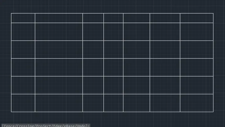
- draw the lines and the required lines by using the line command in the autocad then trim the extra lines as the required table that has been present in the table by using the line command or offset of the lines which has been present the lines is drawn and the extra lines which has been present is trim using the trim command in autocad then we get required lines in the table as shown in the figure below.
- and by using the multitext command or by copying the text which has been present in the another table the header text has been written or edited and edit the text as per the required and paste it on the row which has been present and edit the text and place the texting height as per the required table as shown in the figure below.
- draw the bottom line and the required lines by using the line command in the autocad then trim the extra lines as the required table.
- rotate the text which has been given as per the table and then make sure that the text settings which has been make as per the table settings and make sure that the text heatings is in bold in the settings os annative in the autocad.
- draw the bottom line and the required lines by using the line command in the autocad then trim the extra lines as the required table
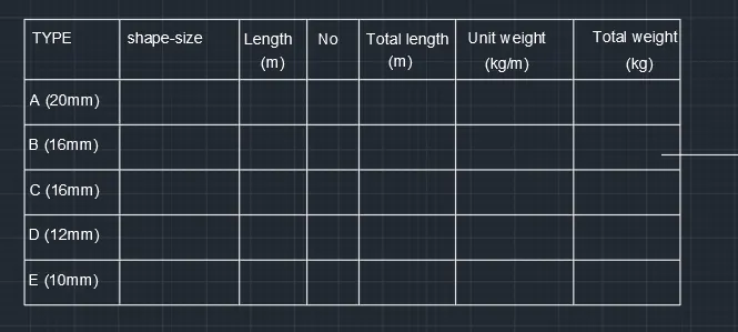
- and next by using the rectangle command in autocad draw a rectangle in the fourth cloumn and then give the dimensions as per the table and the size of the column as per the table and then make it offset of that rectangle to make it offset and then offset dimensions is taken as per the table and make the lines by using the line command and then copy all the circles and then make sure that copy that lines in the required places as per the table.
- and draw the remaing circles by using the line command in the autocad and then copy the lines and place it as per the table.
- and by using the multitext command or by copying the text which has been present in the another column the header text has been written or edited and edit the text as per the required and paste it on the row which has been present and edit the text and place the texting height as per the required table as shown in the figure below.
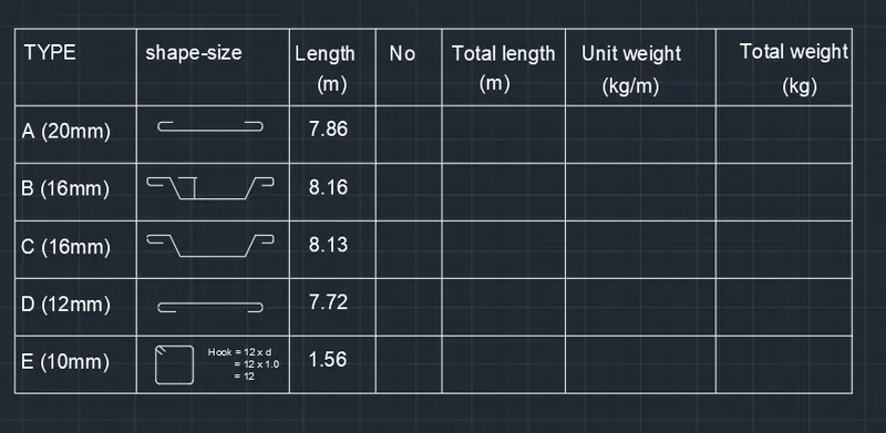
- next by using the rectangle command in autocad draw a rectangle in the fourth cloumn and then give the dimensions as per the table and the size of the column as per the table and then make it offset of that rectangle to make it offset and then offset dimensions is taken as per the table and make the circles by using the circle command and then copy all the lines and then make sure that copy that circles in the required places as per the table.
- and draw the remaing lines by using the line command in the autocad and then copy the lines and place it as per the table.
- and by using the multitext command or by copying the text which has been present in the another column the header text has been written or edited and edit the text as per the required and paste it on the row which has been present and edit the text and place the texting height as per the required table as shown in the figure below.
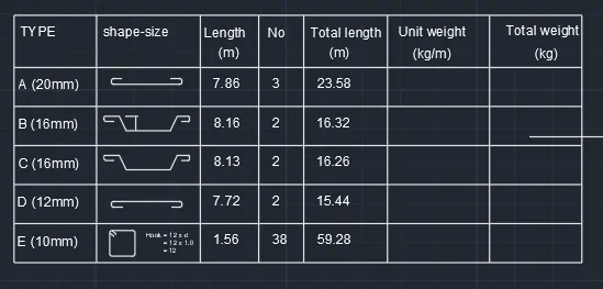
- next by using the rectangle command in autocad draw a rectangle in the fourth cloumn and then give the dimensions as per the table and the size of the column as per the table and then make it offset of that rectangle to make it offset and then offset dimensions is taken as per the table and make the circles by using the circle command and then copy all the circles and then make sure that copy that circles in the required places as per the table.
- and by using the multitext command or by copying the text which has been present in the another column the header text has been written or edited and edit the text as per the required and paste it on the row which has been present and edit the text and place the texting height as per the required table as shown in the figure below.
- draw and complete the table by using the command and then edit the tables by using multi text commands as shown in figure below.
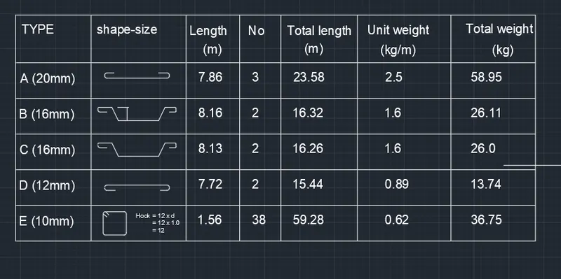
- To make the table as a single block then select the block option and create the block to create the block select on create block on view option and then for creating a block we have to pick the point ie the reference point and then select the lines or the objects which has to make block and then if we want to make annotative make annottive and then press ok.
- here to create block click on create block option and create the block name in the block name option then pick up the reference point and then slect the texts and lines which have to make block and then press ok to crate the block.
- Now, you need to tell AutoCAD what the insertion point should be. In other words, when you place the block, the point about which the block appears at your cursor Click the Select Objects button and select the objects you want to be stored in the block.