Creating Bar Bending schedule, Different Door types, and Creation of standard drawing templates using AutoCad
AIM:
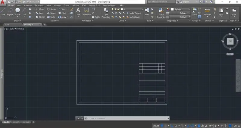
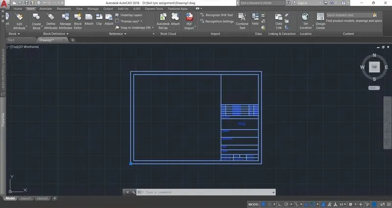
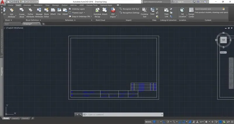
The aim is to draw the title block of the paper size A3, to understand the method of creating a title block and how to save it as a template. Which can be reused whenever required.
INTRODUCTION:
The title block is a must entity for any auto-cad drawing, a title block gives various information apart from the proper presentation of the drawing.
PROCEDURE:
Step l:
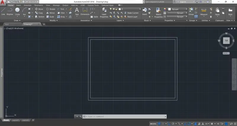
Rectangle command was used to draw the A3 paper size 420x297
Step 2:
An Offset command was used to get the inner space. Using the line command and the offset command various partitions in the title block are
drawn.
Step3:
Command mtext was used to write the text by picking text height as 4.
Step4:
Scale command was used to scale down a few of the text lines.
STEP 5
The create block option is used to create this into a block.
RESULT:

__________________________________________________________________________________
AIM:
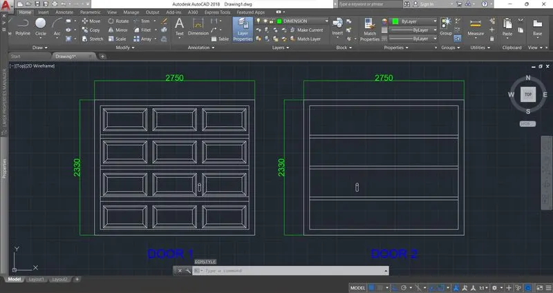
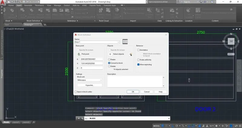
The aim is to draw the elevation of two different doors. then they were converted to blocks that can be reused whenever required.
INTRODUCTION:
The door block is a must entity for any house elevation drawing, the conversion of any drawing will help to reuse the block again and again. Making a drawing detail into a block has many advantages like it saves time, being easy to apply, and converting and recalling the block procedure is very easy.
PROCEDURE:
The following procedure is followed
Step1:
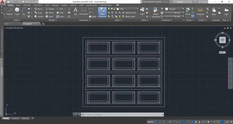
Rectangle command was used to draw the outer dimensions as shown in the image.
Step2:
Offset command was used to get the inner space. Using the line command and the offset command various rectangles were drawn.
Step3:
Command mtext was used to write the text by picking text height as 4.
The following drawing was achieved
STEP 4
The create block option is used to create this into a block.
RESULT:
______________________________________________________________________________
AIM:
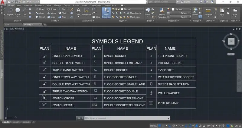
The aim is to draw a table showing the various attributes used in the electrical layout. Here the various entities of electrical details were drawn and converted to blocks, which can be reused whenever required in any drawings.
INTRODUCTION:
The block is a very useful command and tool to convert the details which can be reused without any distortions in size and shape. various electrical symbols were drawn and converted to blocks. Symbols have lots of importance, a small symbol can convey specific information at a particlar location.
PROCEDURE:
Step l:
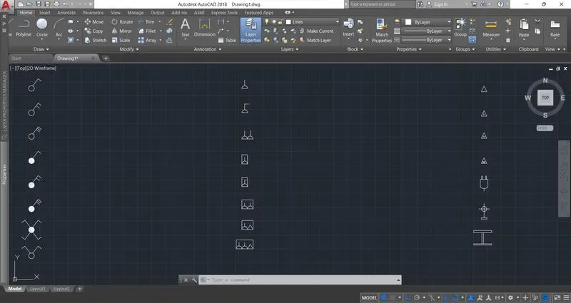
Rectangle circles, lines, hatches, offset, and mirrors were used to draw the symbols as shown in
the image.
Step2:
Block command was used to convert the symbols to blocks.
Step3:
A command table was used to define the various electrical symbols. the image below gives
the details. In the first row, the block was inserted and in the adjacent row, its definition was given.
Step4:
The following drawing was achieved
RESULT :
_________________________________________________________________________________________
AIM:
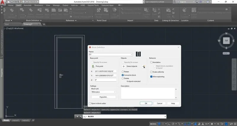
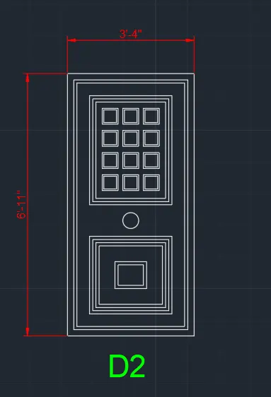
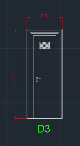
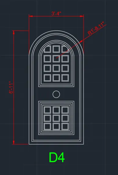
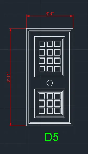
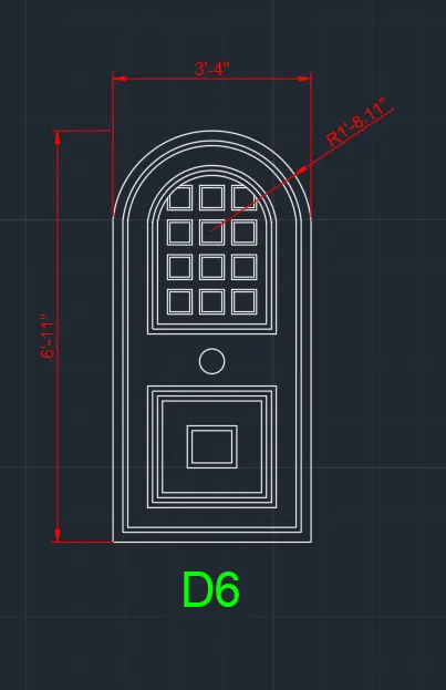
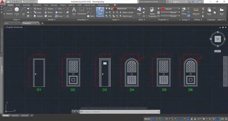
The aim is to draw the elevation of 6 different doors, then they were converted to blocks that can be reused whenever required.
INTRODUCTION:
The door block is a must entity for any house elevation drawing, the conversion of any drawing will help to reuse the block again and again.
PROCEDURE:
Step l:
Rectangle command was used to draw the outer dimensions as shown in the image.
Step 2:
Offset command was used to get the inner space.
Using the line command and the offset command various rectangles were drawn.
Arc command was used to draw the arc for the doors.
Step3:
Command mtext was used to write the text by picking text height as 4.
Step4:
The block option is used to convert the drawing into a block.
Similarly all the doors were drawn.
RESULT :
__________________________________________________________________________________________
AIM:
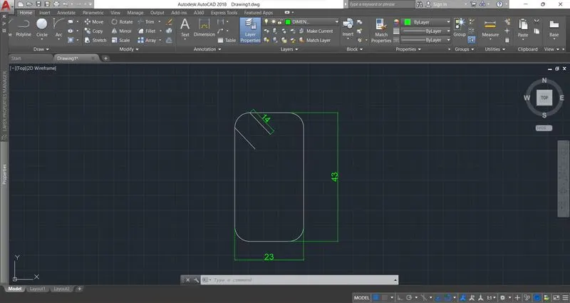
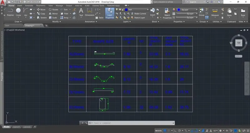
The aim is to draw the bar bending schedule, different bends were drawn first and they were converted into blocks. A table was then drawn and the blocks were inserted to it.
INTRODUCTION:
The Block is a must entity in an AutoCAD drawing, it has got many applications, one of its applications is to prepare a bar bending schedule using table command. The conversion of any drawing will help to reuse the block again and again.
PROCEDURE:
Step1:
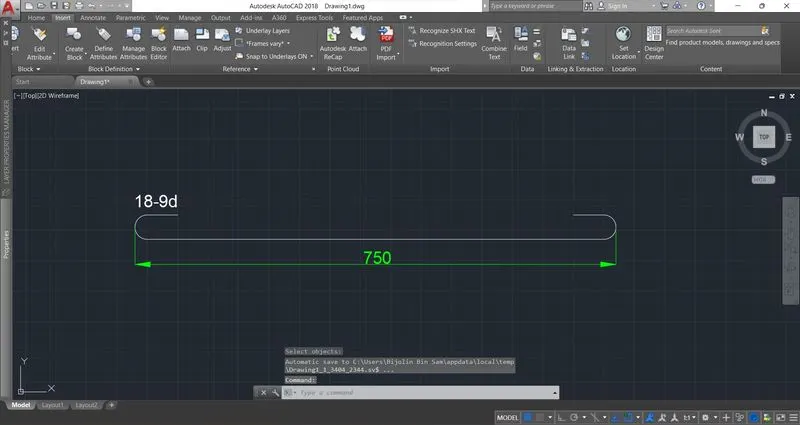
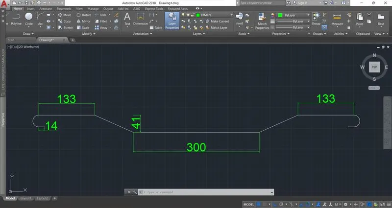
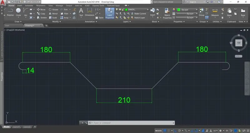
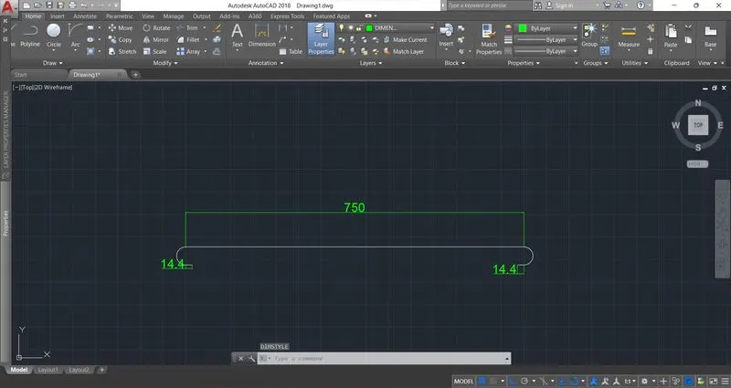
Line command was used to draw the different shapes and bends as shown in the image.
Arc command was used to draw the bends.
Fillet command was used to provide radius to the bendings.
Step2:
Dimensions were given to the drawings accordingly.
Step3:
The drawings were separately created into blocks
Step4:
Using rectangle, line and offset commands, the table was created.
Text were inserted using mtext command.
Step5:
The blocks were inserted to the space in the table.
RESULT: