Creating Bar Bending schedule, Different Door types, and Creation of standard drawing templates using AutoCad
1)TEMPLATE USING TEXT AND ATTRIBUTES
AIM: To create the template contains text and attributes using AutoCAD.
INTRODUCTION: The template contains text and attributes using AutoCAD is created by Lines. The procedure and result should be written after creating the template using text and attributes.
STEP 1:
- Open the AutoCAD software and click start Drawing tab.
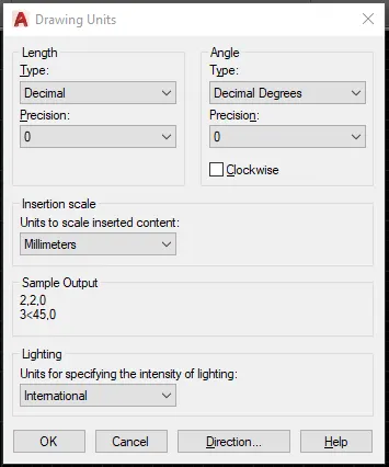
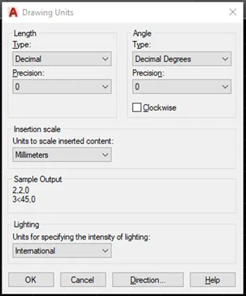
- Enter UNITS in command box.
- Select DECIMAL in TYPE, 0.0 in PRECISION and MILLIMETERS in UNITS TO SCALE INSERTED CONTENT. Press OK.
STEP 2:
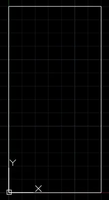
- Enter REC in command box
- Click dimensions
- Enter 140 as length
- Enter 70 as width
STEP 3:
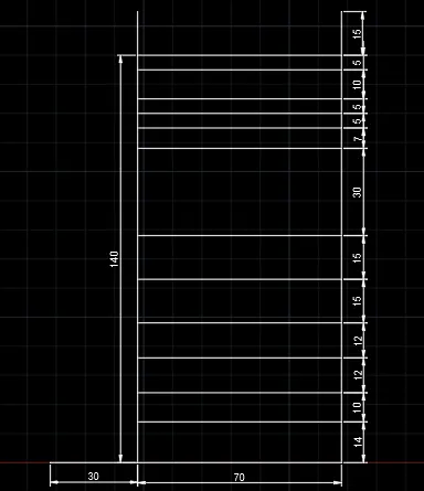
- Enter L in command box
- Click the two upper corners of the rectangle
- Enter 15 as next point
- Enter O in command box
- Enter 5,10,7,30,15,12 and 14 as offset distances
- Place it at the required place
- Enter L in command box
- Click on the lower left corner
- Enter 30 as next point
STEP 4:
- Enter O in command box
- Enter 7 as offset distance
- Select the left line and place it inwards
- Enter O in command box
- Enter 10 as offset distance
- Select the right line and place it inwards
- Enter O in command box
- Enter 7 as offset distance
- Select the right side 10mm line and place it inwards
- Enter O in command box
- Enter 25 as offset distance
- Select the left line and place it inwards
- Enter O in command box
- Enter 15 as offset distance
- Select the 25mm line and place it inwards
- Place it again
- Enter TR in command box
- Delete the unwanted lines
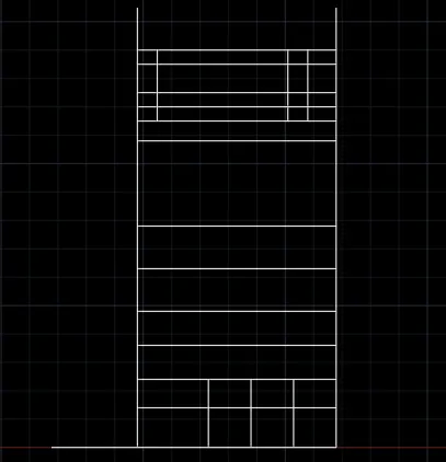
STEP 5:
- Enter MTEXT in command box
- Select CALIBRI in text style
- Enter 3 as text height
- Enter the text in 4 rows in the table
- Enter DT in command box
- Enter 2 as text height
- Enter the text after 4th row in the table
- Enter MTEXT in command box
- Enter 3 as text height
- Select ARIAL in text style
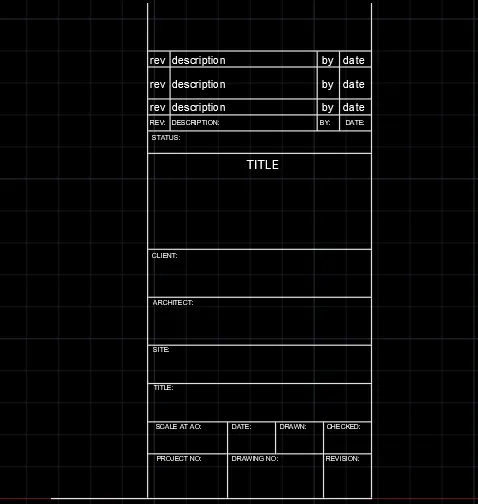
STEP 6:
- Click LAYER PROPERTIES in RIBBON
- Click NEW LAYER
- Enter TEXT and TITLE BLOCK in NAME
- Select 150 for TEXT and 174 for TITLE BLOCK
- Select 0.30mm as line weight in NAME
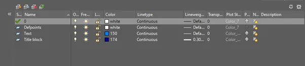
STEP 7:
- Select the right-side vertical line and bottom horizontal line
- Implement TITLE BLOCK layer in these two lines
- Select other lines and implement TEXT layer
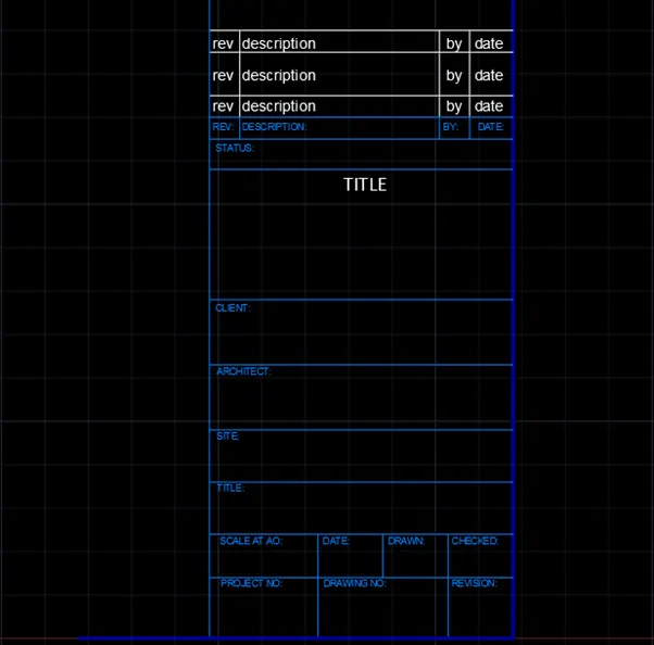
STEP 8:
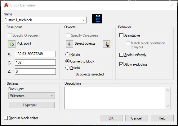
- Enter B in command box
- Enter Custom1_titleblock in NAME
- Pick the midpoint of the template
- Select the template as a whole
- Click CONVERT TO BLOCK
- Click OK
STEP 9:
- Enter REC in command box
- Click DIMENSIONS
- Enter 400 as length
- Enter 40 as width
- Enter EXPLODE in command box
- Separate the four lines as individual lines

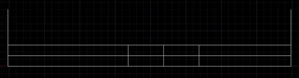
STEP 10:
- Enter L in command box
- Click on the two upper corners
- Enter 50 as next point
- Press ENTER
- Enter O in command box
- Enter 175 as offset distance
- Select the left line and place it inwards
- Enter O in command box
- Enter 65 as offset distance
- Select the 175mm line and place it inwards
- Enter O in command box
- Enter 60 as offset distance
- Select the 65mm line and place it inwards
- Enter O in command box
- Enter 20 as offset distance
- Select the bottom line and place it upwards
- Press ENTER
STEP 11:
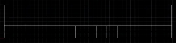
- Enter O in command box
- Enter 35 as offset distance
- Select the 175mm line and place it inwards
- Enter O in command box
- Enter 30 as offset distance
- Select the 65mm line and place it inwards
- Press ENTER
- Enter TR in command box
- Delete the unwanted lines
STEP 12:
- Click LAYER PROPERTIES
- Enter NEW LAYER
- Enter TITLE BLOCK 2 in NAME
- Select 0.30mm in LINEWEIGHT

STEP 13:
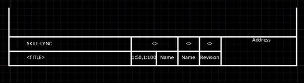
- Select the Table and implement the line weight
- Enter DT in command box
- Enter 5 as text height
- Enter the text in the template
- Press ENTER
STEP 14:
- Enter DT in command box
- Enter 3 as text height
- Enter the text in the template
- Press ENTER
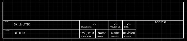
STEP 15:
- Enter L in command box
- Trace the right-side vertical line
- Enter 75 as first point
- Enter 40 as next point
- Press ENTER
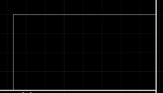
STEP 16:
- Enter O in command box
- Enter 7 as offset distance
- Select the upper horizontal line and place it downwards
- Enter O in command box
- Enter 13 as offset distance
- Select the upper 7mm line and place it downwards
- Enter O in command box
- Enter 6 as offset distance
- Select the upper 13mm line and place it downwards
- Place it again
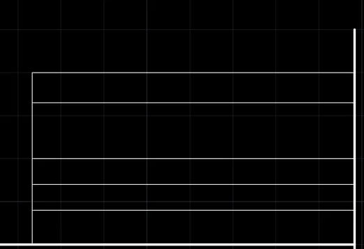
STEP 17:
- Enter O in command box
- Enter 9 as offset distance
- Select the left-side vertical line and place it behind
- Enter O in command box
- Enter 42 as offset distance
- Select the left-side 42mm line and place it behind
- Enter O in command box
- Enter 11 as offset distance
- Select the left-side vertical line and place it behind
- Press ENTER
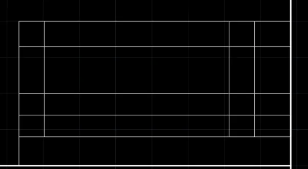
STEP 18:
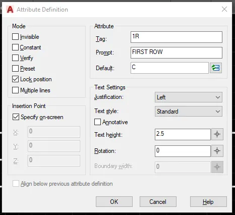
- Enter ATTDEF in command box
- Enter 1R in TAG
- Enter FIRST ROW in PROMPT
- Enter C in DEFAULT
- Press OK
STEP 19:
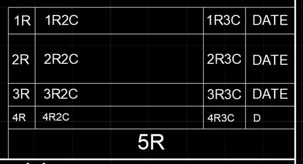
- Place it at 1st row 1st column
- Again,do step 18 for other columns and rows
- Place those in the required columns and rows
STEP 20:
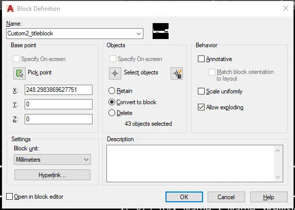
- Enter B in command box
- Enter Custom2_titleblock in NAME
- Pick the midpoint of the template
- Select the template as a whole
- Click CONVERT TO BLOCK
- Press OK
STEP 21:
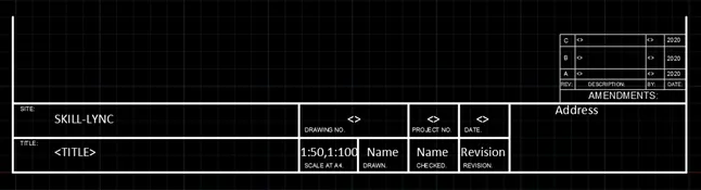
- Create the block
- The tag will be changed to concern values
RESULT:
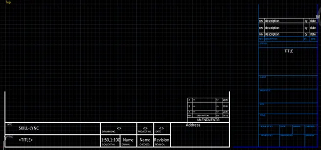
The Template consists of text and attribute is created by lines using AutoCAD. The step-by-step procedure for creating template is also explained. The Dimension is also entered in the diagram.
2)DOORS TYPE FOR WAREHOUSE
AIM: To create the doors type for warehouse and blocks using AutoCAD.
INTRODUCTIO
N: The doors type for warehouse and blocks using AutoCAD is created by Lines. The procedure and result should be written after creating the doors type for warehouse and blocks.
STEP 1:
- Open the AutoCAD software and click start Drawing tab.
- Enter UNITS in command box.
- Select DECIMAL in TYPE, 0.0 in PRECISION and MILLIMETERS in UNITS TO SCALE INSERTED CONTENT. Press OK.
STEP 2:
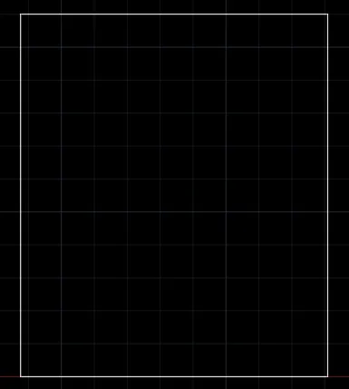
- Enter REC in command box
- Click dimensions
- Enter 2330 as length
- Enter 2750 as width
- Enter EXPLODE in command box
- Make the rectangle into individual separate lines
STEP 3:
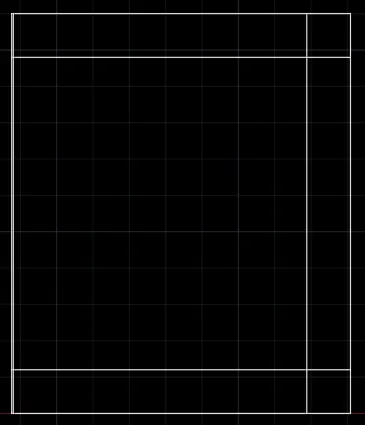
- Enter O in command box
- Enter 10 as offset distance
- Select the left-side line and place it inwards
- Enter O in command box
- Enter 300 as offset distance
- Select the right-side line and place it inwards
- Select the upper line and place it inwards
- Select the lower line and place it inwards
- Press ENTER
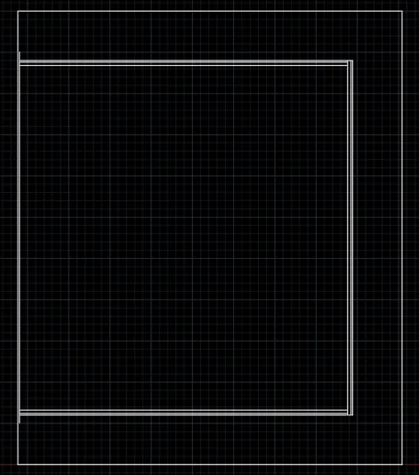
STEP 4:
- Enter O in command box
- Enter 10 as offset distance
- Select the 300mm line and place it inwards
- Repeat the above step for 2 more times
- Enter O in command box
- Enter 20 as offset distance
- Select the 10mm line and place it inwards
- Repeat the above step for 2 more times
- Press ENTER
STEP 5:
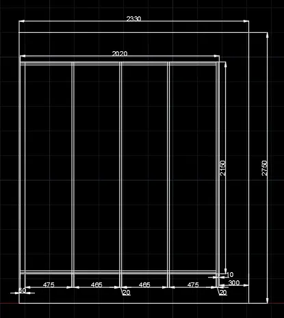
- Enter O in command box
- Enter 50 as offset distance
- Select the 10mm left-side line and place it inwards
- Enter O in command box
- Enter 475 as offset distance
- Select the 50mm line and place it inwards
- Enter O in command box
- Enter 20 as offset distance
- Select the 475mm line and place it inwards
- Enter O in command box
- Enter 465 as offset distance
- Select the 20mm line and place it inwards
- Enter O in command box
- Enter 20 as offset distance
- Select the 465mm line and place it inwards
- Enter O in command box
- Enter 475 as offset distance
- Select the 20mm line and place it inwards
- Press ENTER
- Enter TR in command box
- Delete all the unwanted lines
STEP 6:
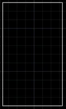
- Enter REC in command box
- Enter 350 as length
- Enter 600 as width
STEP 7:
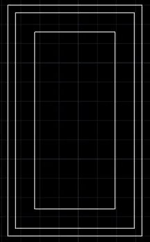
- Enter O in command box
- Enter 20 as offset distance
- Select the rectangle and place it inwards
- Enter O in command box
- Enter 50 as offset distance
- Select the inner rectangle and place it inwards
- Press ENTER
STEP 8:
- Switch off ORTHOMODE
- Enter L in command box
- Connect all the outer rectangle corner with inner rectangle corner
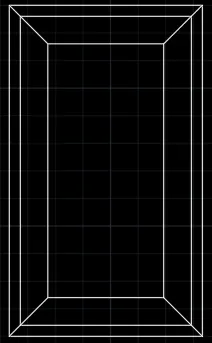
STEP 9:
- Enter B in command box
- Enter DOOR in NAME
- Pick the midpoint of door
- Select the door as a whole
- Click CONVERT TO BLOCK
- Press OK
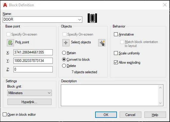
STEP 10:
- Enter CO in command box
- Copy the rectangle and place 3 rectangles horizontally
- Enter CO in command box
- Select the 4 rectangles
- Click ARRAY
- Enter 3 as number of items
- Click FIT and place it
- Press OK
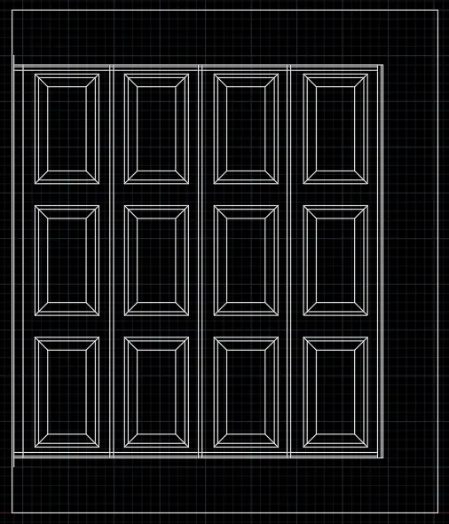
STEP 11:
- Switch on ORTHOMODE
- Enter L in command box
- Tracing the second door bottom line, enter 115
- Enter 120 as next point vertically
- Enter O in command box
- Enter 20 as offset distance
- Select the 120mm line and place it behind
- Enter L in command box
- Tracing the 120mm line, enter 45 as first point
- Enter 100 as next point horizontally
- Press ENTER
- Enter O in command box
- Enter 30 as offset distance
- Select the 100mm line and place it downwards
- Enter ARC in command box
- Create an arc at either side

STEP 12:
- Enter DIMS in command box
- Select SYMBOLS AND ARROWS, Enter 50 as arrow size
- Select TEXT, Enter 50 as text height
- Enter DIML in command box and drag the dimensions.
- Enter DT in command box. Enter 50 as TEXT HEIGHT and 0 as TEXT ROTATION ANGE.
- Enter TEXT.
- Enter CO in command box. Copy the text and place it in another location.
- Enter TEXTEDIT in command box. Using this, editing in text can be done.
- Select the text and select the layer. Make it to red colour.
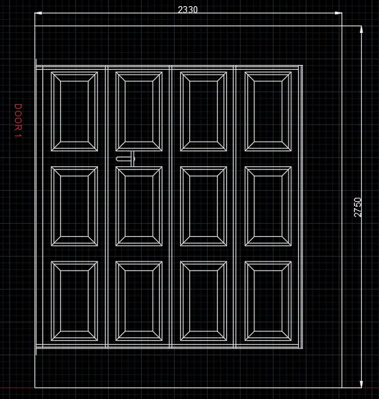
STEP 13:
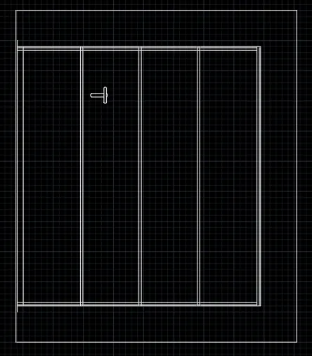
- Copy the door 1 diagram except the doors
- Place it at particular distance
STEP 14:
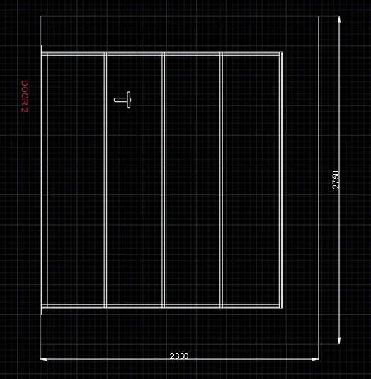
- Enter DIMS in command box
- Select SYMBOLS AND ARROWS, Enter 50 as arrow size
- Select TEXT, Enter 50 as text height
- Enter DIML in command box and drag the dimensions.
- Enter DT in command box. Enter 50 as TEXT HEIGHT and 0 as TEXT ROTATION ANGE.
- Enter TEXT.
- Enter CO in command box. Copy the text and place it in another location.
- Enter TEXTEDIT in command box. Using this, editing in text can be done.
- Select the text and select the layer. Make it to red colour.
RESULT:
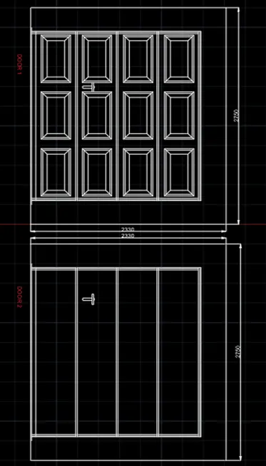
The Doors type for warehouse and blocks is created by lines using AutoCAD. The step-by-step procedure for creating doors type for warehouse and blocks is also explained. The Dimension is also entered in the diagram.
3)CREATING BLOCKS IN LEGEND
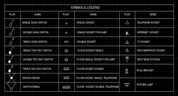
AIM: To create the blocks of each symbol and place it in legend using AutoCAD.
INTRODUCTION: The Blocks of each symbol and place it in legend using AutoCAD is created by Lines. The procedure and result should be written after creating the blocks of each symbol and place it in legend.
STEP 1:
- Open the AutoCAD software and click start Drawing tab.
- Enter UNITS in command box.
- Select DECIMAL in TYPE, 0.0 in PRECISION and MILLIMETERS in UNITS TO SCALE INSERTED CONTENT. Press OK.
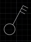
- Enter C in command box
- Enter 50 as radius
- Switch off ORTHOMODE
- Click on the circle and enter 200 as first point
- Enter 50 as next point
- Click ENTER

STEP 2:
- Enter CO in command box
- Copy the single gang switch and place it aside
- Press ENTER
- Enter O in command box
- Enter 30 as offset distance
- Select the 50mm line and place it below

STEP 3:
- Enter CO in command box
- Copy the double gang switch and place it aside
- Press ENTER
- Enter O in command box
- Enter 30 as offset distance
- Select the 2nd 50mm line and place it below
STEP 4:
- Enter CO in command box
- Copy the single gang switch and place it aside
- Press ENTER
- Enter O in command box
- Enter 40 as offset distance
- Select the circle and click inside
- Enter H in command box
- Click SOLID in ribbon
- Pick internal circle
- Implement the hatch

STEP 5:
- Enter CO in command box
- Select the double two-way switch and place it at particular distance
- Enter O in command box
- Enter 50 as offset distance
- Place the offset at particular distance
- Press ENTER
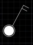
STEP 6:
- Enter CO in command box
- Select the triple two-way switch and place it at particular distance
- Enter O in command box
- Enter 50 as offset distance
- Place the offset at particular distance
- Press ENTER
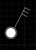
STEP 7:
- Enter CO in command box
- Select the single two-way switch and place at particular distance
- Enter MI in command box
- Select the line and make mirrored object
- Repeat it for 2 more times
- Enter M in command box
- Move it at required place

STEP 8:
- Enter CO in command box
- Select the switch cross and place it at particular place
- Delete the hatch and inner circle
- Delete the 2 lines from lower side

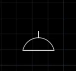
STEP 9:
- Enter L in command box
- Enter 0,0 as first point
- Enter 100 as next point
- Enter ARC in command box
- Pick two points and create an arc
- Enter L in command box
- Click the midpoint
- Enter 20 as next point
- Press ENTER
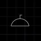
STEP 10:
- Enter CO in command box
- Copy the single socket and place it at particular place
- Enter L in command box
- Click the line
- Enter 10 as next point
STEP 11:
- Enter CO in command box
- Select the single socket and place it particular place
- Place another single socket right after it
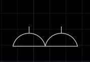
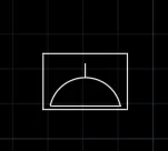
STEP 12:
- Enter CO in command box
- Copy the single socket and place it at particular place
- Enter REC in command box
- Enter 120 as length
- Enter 180 as width
- Copy the rectangle and place it around the object
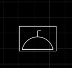
STEP 13:
- Enter CO in command box
- Copy the floor socket single and place it at particular position
- Enter L in command box
- Click the line
- Enter 10 as next point
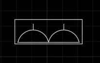
STEP 14:
- Enter CO in command box
- Copy the double socket and place it at particular position
- Enter REC in command box
- Enter 220 as length
- Enter 80 as width
- Place the rectangle and place around the object
STEP 15:
- Enter CO in command box
- Copy the floor socket double and place it at particular place
- Delete the other object
- Switch off ORTHOMODE
- Enter L in command box
- Click the point
- Enter 80 as next point
- Click on the other point
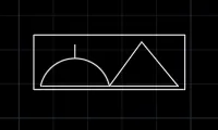
STEP 16:
- Enter CO in command box
- Copy the double socket and place it at particular place
- Switch off ORTHOMODE
- Enter L in command box
- Click on the second socket
- Enter 80 as next point
- Close it by connecting to the horizontal line
- Enter REC in command box
- Enter 320 as length
- Enter 80 as width
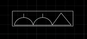
STEP 17:
- Enter L in command box
- Enter 0,0 as first point
- Enter 100 as next point
- Switch off ORTHOMODE
- Enter 95 as next point
- Close the triangle
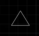
STEP 18:
- Enter CO in command box
- Copy the telephone socket and place it at particular place
- Enter DT in command box
- Enter 30 as text height
- Enter the text into the triangle

STEP 19:
- Enter CO in command box
- Copy the telephone socket and place it at particular place
- Enter DT in command box
- Enter 30 as text height
- Enter the text into the triangle

STEP 20:
- Enter CO in command box
- Copy the telephone socket and place it at particular place
- Enter DT in command box
- Enter 30 as text height
- Enter the text into the triangle

STEP 21:
- Enter L in command box
- Enter 0,0 as first point
- Enter 100 as next point
- Enter 55 as next point on either side
- Switch off ORTHOMODE
- Click the 55mm line
- Enter 52 as next point
- Close the line
- Press ENTER
- Click the midpoint
- Enter 100 as next point
- Enter L in command box
- Trace the horizontal line
- Enter 20 as first point
- Enter 50 as next point
- Enter O in command box
- Enter 60 as offset distance and place it
- Select the 50mm line and make it as 0.30mm line weight
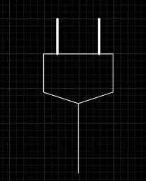
STEP 22:
- Enter C in command box
- Enter 50 as radius
- Enter L in command box
- Enter 0,0 as first point
- Enter 120 as next point
- Copy the line and rotate it to 90
- Place it in the circle
- Enter L in command box
- Trace the line and enter 3 as first point
- Enter 50 as next point
- Enter O in command box
- Enter 6 as offset distance
- Enter L in command box
- Click on the 50mm line bottom corner
- Enter 63 as next point
- Enter 10 as next point
- Enter 130 as next point
- Enter 10 as next point
- Close the line
- Press ENTER
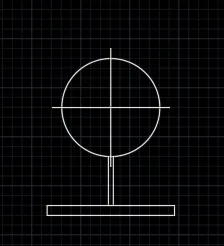
STEP 23:
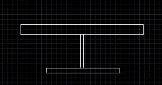
- Enter REC in command box
- Enter 250 as length
- Enter 20 as width
- Enter L in command box
- Trace the rectangle bottom side
- Enter 122 as first point
- Enter 70 as next point
- Enter O in command box
- Enter 6 as offset distance
- Place it at required place
- Enter REC in command box
- Enter 150 as length
- Enter 10 as width
- Enter M in command box
- Move the rectangle to the particular position
STEP 24:
- Enter B in command box
- Enter SINGLE GANG SWITCH in NAME
- Pick the midpoint of an object
- Select the object
- Select DELETE
- Click OK
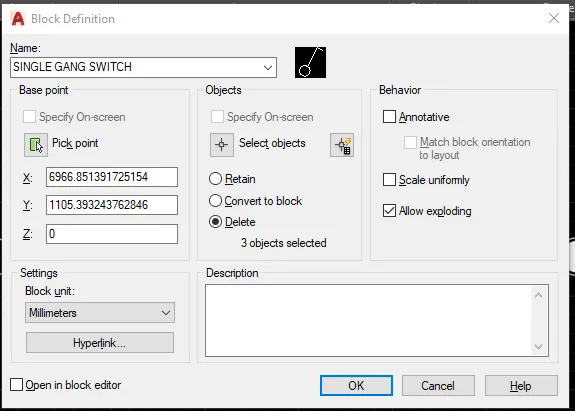
- Create blocks for all the items
STEP 25:
- Enter REC in command box
- Enter 7500 as length
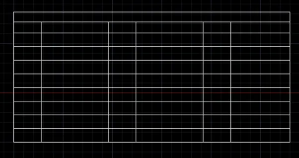
- Enter 3300 as width
- Enter EXPLODE in command box
- Create individual lines
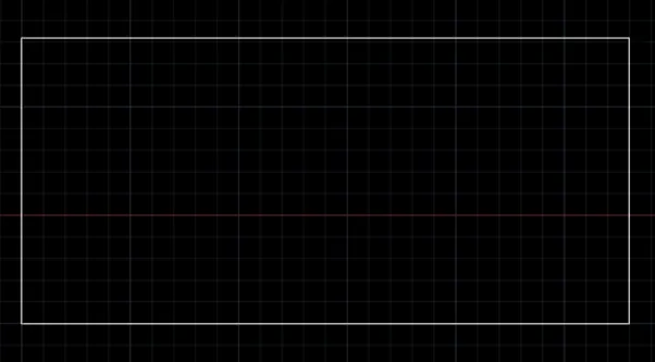
STEP 26:
- Enter O in command box
- Enter 250 as offset distance
- Select the upper line and place
- Enter O in command box
- Enter 280 as offset distance
- Select the 250mm line and place
- Enter O in command box
- Enter 346 as offset distance
- Select the upper line and place
- Repeat the same step for other offsets
- Enter O in command box
- Enter 700 as offset distance
- Select the left line and place
- Enter O in command box
- Enter 1700 as offset distance
- Select the 700mm line and place
- Enter O in command box
- Enter 700 as offset distance
- Select the 1700mm line and place
- Enter O in command box
- Enter 2000 as offset distance
- Select the 700mm line and place
- Enter O in command box
- Enter 700 as offset distance
- Select the 2000mm line and place
- Press ENTER
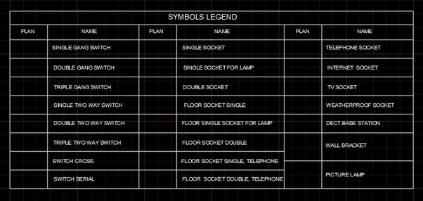
STEP 27:
- Enter DT in command box
- Enter 100 as text height
- Enter the first text at the top
- Enter DT in command box
- Enter 70 as text height
- Enter the text in the columns
STEP 28:
- Enter B in command box
- Enter SINGLE GANG SWITCH in NAME
- Pick the midpoint of an object
- Select the whole object
- Click DELETE
- Click OK

- Create blocks for all the items
STEP 29:
- Enter I in command box
- Select the items from the dropdown
- Click OK
- Place it at required place
RESULT:
The Blocks in legend is created by lines using AutoCAD. The step-by-step procedure for creating blocks in legend is also explained. The Dimension is also entered in the diagram.
4)DOOR TYPE FOR RESIDENTIAL BUILDING
AIM: To create the door type for residential building as a block using AutoCAD.
INTRODUCTION: The door type for residential building as a block using AutoCAD is created by Lines. The procedure and result should be written after creating the door type for residential building as a block.
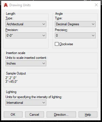
STEP 1:
- Open the AutoCAD software and click start Drawing tab.
- Enter UNITS in command box.
- Select ARCHITECTURAL in TYPE, 0’0” in PRECISION and INCHES in UNITS TO SCALE INSERTED CONTENT. Press OK.
STEP 2:
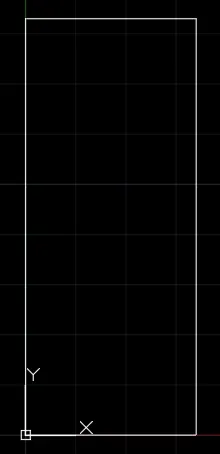
- Enter REC in command box
- Enter 0,0 as first corner point
- Enter 2’10” as length
- Enter 6’11” as width
- Enter EXPLODE in command box
- Create individual lines
STEP 3:
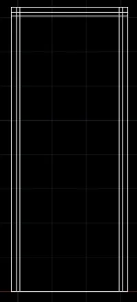
- Enter O in command box
- Enter 2” as offset distance and place it inwards
- Repeat it for 2 sides
- Enter O in command box
- Enter 1” as offset distance and place it inwards
- Repeat it for 2 sides
- Press ENTER
STEP 4:
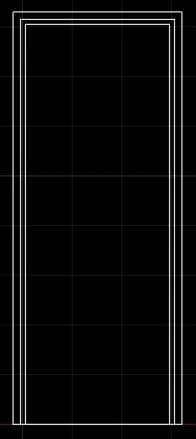
- Enter F in command box
- Click the two lines
- Make the corners
- Repeat for other lines
STEP 5:
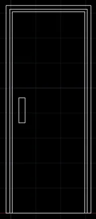
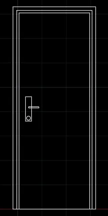
- Enter REC in command box
- Enter 2” as length
- Enter 10” as width
- Move the rectangle to the required position
STEP 6:
- Enter C in command box
- Enter 1” as radius
- Place it into the small rectangle
- Enter REC in command box
- Enter 4” as length
- Enter 1” as width
- Enter ARC in command box
- Create arc at left-side
- Press ENTER
STEP 7:
- Enter DIMS in command box
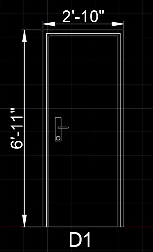
- Select SYMBOLS AND ARROWS, Enter 5” as arrow size
- Select TEXT, Enter 5” as text height
- Enter DIML in command box and drag the dimensions.
- Enter DT in command box. Enter 6” as TEXT HEIGHT and 0 as TEXT ROTATION ANGE.
- Enter TEXT.
- Enter CO in command box. Copy the text and place it in another location.
- Enter TEXTEDIT in command box. Using this, editing in text can be done.
STEP 8:
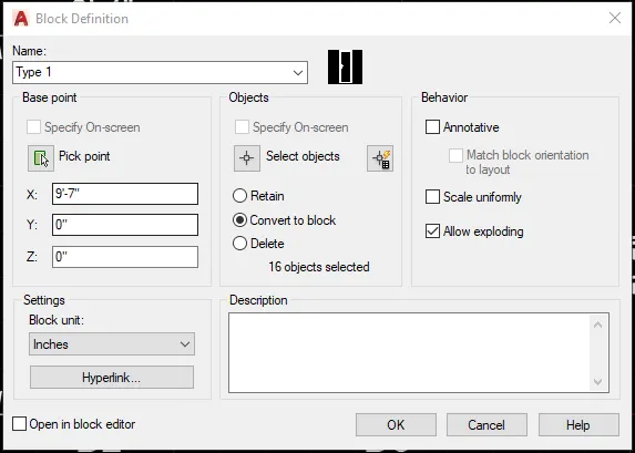
- Enter B in command box
- Enter Type 1 in NAME
- Pick the point
- Select the object
- Click CONVERT TO BLOCK
- Press OK
STEP 9:
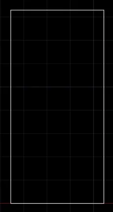
- Enter REC in command box
- Enter 3’4” as length
- Enter 6’11” as width
- Enter EXPLODE in command box
- Create individual lines
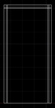
STEP 10:
- Enter O in command box
- Enter 2” as offset distance and place it
- Repeat for 2 other sides
- Enter O in command box
- Enter 1” as offset distance and place it
- Repeat for 2 other sides
STEP 11:
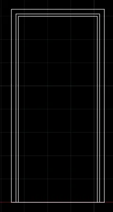
- Enter F in command box
- Select the 2 lines
- Make it as corners
- Repeat the same step for other lines
STEP 12:
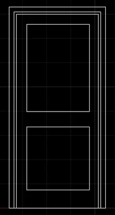
- Enter REC in command box
- Enter 4” as first corner point
- Enter 2’2” as length
- Enter 3’ as width
- Enter REC in command box
- Enter 2’2” as length
- Enter 2’2” as width
- Enter M in command box
- Move the square to 6” from the rectangle
STEP 13:
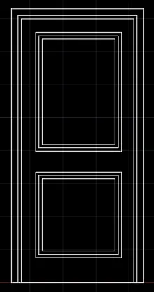
- Enter O in command box
- Enter 1” as offset distance
- Place it inwards from the rectangle
- Repeat it again
- Repeat the same step for the square
STEP 14:
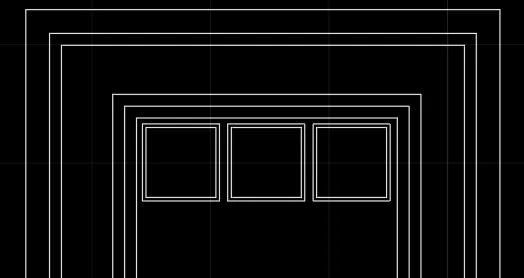
- Enter REC in command box
- Enter 7” as length
- Enter 7” as width
- Move the rectangle to 1” downwards
- Enter CO in command box
- Copy the square two times
STEP 15:
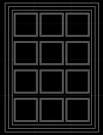
- Enter CO in command box
- Copy the 3 squares
- Click ARRAY in command box
- Enter 4 as number of items
- Select the objects
- Click FIT
- Place the object
STEP 16:
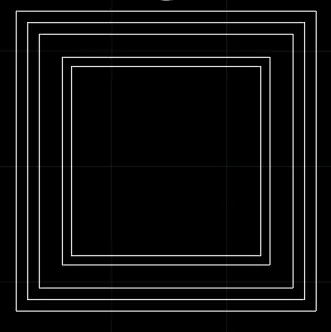
- Enter O in command box
- Enter 2” as offset distance
- Place it inwards
- Enter O in command box
- Enter 1” as offset distance
- Place it inwards
STEP 17:
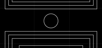
- Enter C in command box
- Enter 2” as radius
- Place it in the appropriate place
STEP 18:
- Enter M in command box
- Move the rectangle, circle and square in the required place
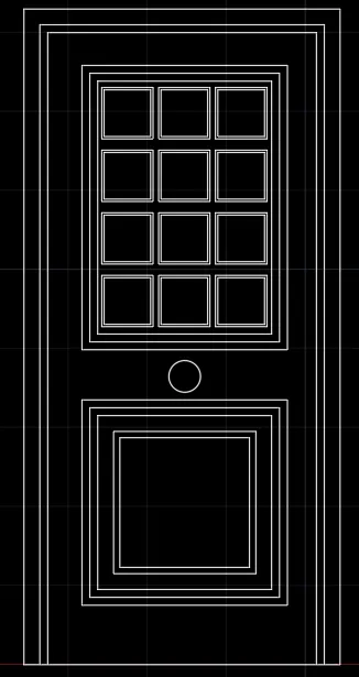
STEP 19:
- Enter DIMS in command box
- Select SYMBOLS AND ARROWS, Enter 5” as arrow size
- Select TEXT, Enter 5” as text height
- Enter DIML in command box and drag the dimensions.
- Enter DT in command box. Enter 6” as TEXT HEIGHT and 0 as TEXT ROTATION ANGE.
- Enter TEXT.
- Enter CO in command box. Copy the text and place it in another location.
- Enter TEXTEDIT in command box. Using this, editing in text can be done.
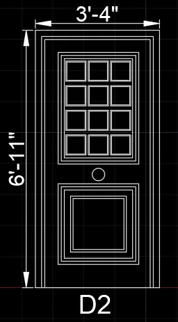
STEP 20:
- Enter B in command box
- Enter Type 2 in NAME
- Pick the point
- Select the object
- Click CONVERT TO BLOCK
- Press OK
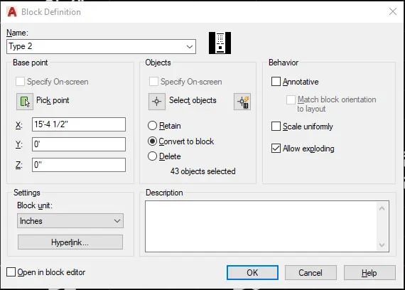
STEP 21:
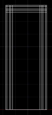
- Enter REC in command box
- Enter 2’9” as length
- Enter 6’11” as width
- Enter EXPLODE in command box
- Create individual lines
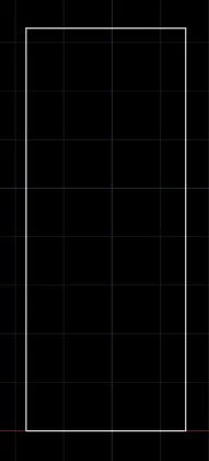
STEP 22:
- Enter O in command box
- Enter 1” as offset distance
- Repeat it for 3 sides
- Enter O in command box
- Enter 2” as offset distance
- Repeat it for 3 sides
- Enter O in command box
- Enter 1” as offset distance
- Repeat it for 3 sides
- Enter O in command box
- Enter 1.5” as offset distance
- Repeat it for 3 sides
- Press ENTER
STEP 23:
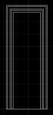
- Enter F in command box
- Select the two lines
- Make corners of the lines
- Repeat for all the lines
STEP 24:
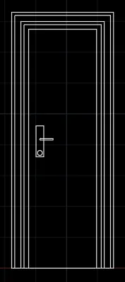
- Enter CO in command box
- Copy the lock
- Place it at required position
STEP 25:
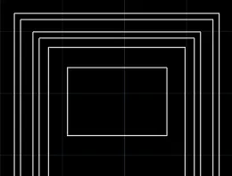
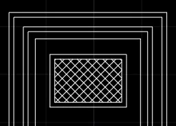
- Enter REC in command box
- Enter 1’4” as length
- Enter 11” as width
STEP 26:
- Enter O in command box
- Enter 1” as offset distance
- Enter H in command box
- Select ANSI37 in hatch pattern
- Enter 0.1” as scale
- Place the hatch
STEP 27:
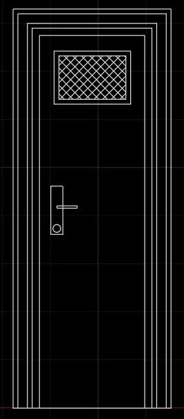
- Enter M in command box
- Move the rectangle and lock
- Place it in required place
STEP 28:
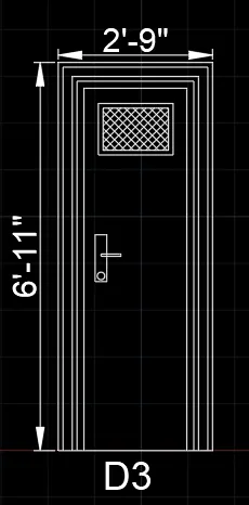
- Enter DIMS in command box
- Select SYMBOLS AND ARROWS, Enter 5” as arrow size
- Select TEXT, Enter 5” as text height
- Enter DIML in command box and drag the dimensions.
- Enter DT in command box. Enter 6” as TEXT HEIGHT and 0 as TEXT ROTATION ANGE.
- Enter TEXT.
- Enter CO in command box. Copy the text and place it in another location.
- Enter TEXTEDIT in command box. Using this, editing in text can be done.
STEP 29:
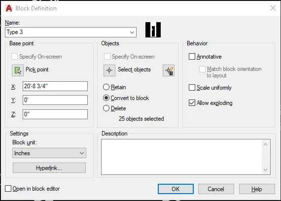
- Enter B in command box
- Enter Type 3 in NAME
- Pick the point
- Select the object
- Click CONVERT TO BLOCK
- Press OK
STEP 30:
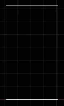
- Enter REC in command box
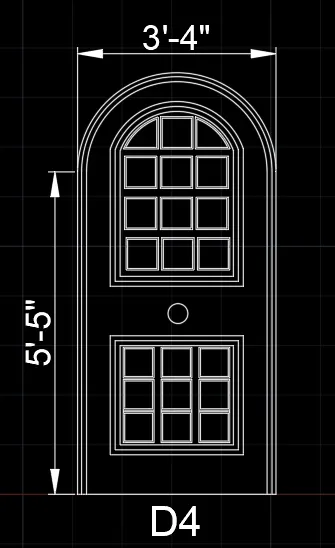
- Enter 3’4” as length
- Enter 5’5” as width
- Enter EXPLODE in command box
- Create individual lines
STEP 31:
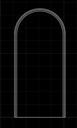
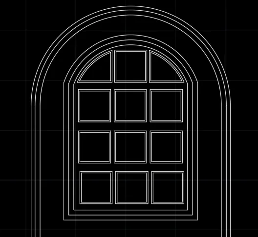
- Enter ARC in command box
- Create an arc
- Enter O in command box
- Enter 1” as offset distance
- Select the arc and place it
- Enter O in command box
- Enter 1.2” as offset distance
- Select the arc and place it
STEP 32:
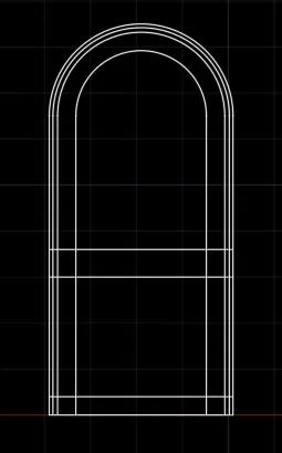
- Enter O in command box
- Enter 5” as offset distance
- Place it 3 sides
- Enter O in command box
- Enter 8” as offset distance
- Place it upwards
- Enter O in command box
- Enter 2’ as offset distance
- Place it upwards
- Enter O in command box
- Enter 10” as offset distance
- Place it upwards
STEP 33:
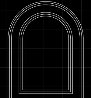
- Enter O in command box
- Enter 1” as offset distance
- Place it 4 sides
- Repeat again
STEP 34:
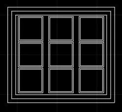
- Enter CO in command box
- Copy the square and place it
- Enter O in command box
- Enter 0.5” as offset distance
- Enter MI in command box
- Create mirrored objects
- Enter CO in command box
- Select the objects
- Click ARRAY
- Enter 4 as number of items
STEP 35:
- Enter CO in command box
- Copy the squares from previous diagram
- Place it at required place
STEP 36:
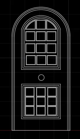
- Enter C in command box
- Enter 2” as radius
- Place it at appropriate place
STEP 37:
- Enter DIMS in command box
- Select SYMBOLS AND ARROWS, Enter 5” as arrow size
- Select TEXT, Enter 5” as text height
- Enter DIML in command box and drag the dimensions.
- Enter DT in command box. Enter 6” as TEXT HEIGHT and 0 as TEXT ROTATION ANGE.
- Enter TEXT.
- Enter CO in command box. Copy the text and place it in another location.
- Enter TEXTEDIT in command box. Using this, editing in text can be done.
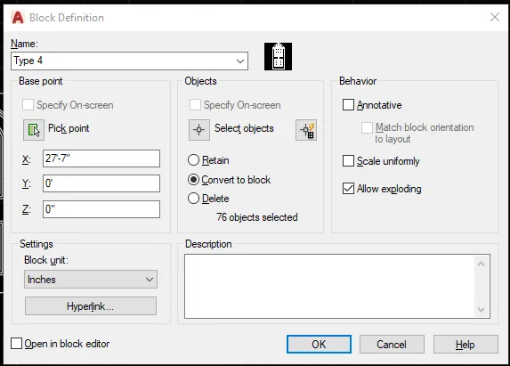
STEP 38:
- Enter B in command box
- Enter Type 4 in NAME
- Pick the point
- Select the object
- Click CONVERT TO BLOCK
- Press OK
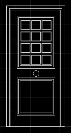
STEP 39:
- Enter CO in command box
- Copy the D2 door
- Delete the inner squares
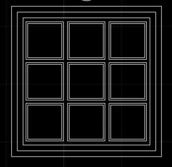
STEP 40:
- Enter CO in command box
- Copy the squares
- Place it in the squares
STEP 41:
- Enter CO in command box
- Place the objects in the required place
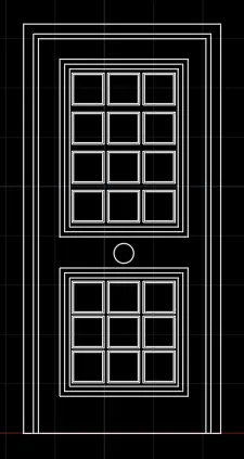
STEP 42:
- Enter DIMS in command box
- Select SYMBOLS AND ARROWS, Enter 5” as arrow size
- Select TEXT, Enter 5” as text height
- Enter DIML in command box and drag the dimensions.
- Enter DT in command box. Enter 6” as TEXT HEIGHT and 0 as TEXT ROTATION ANGE.
- Enter TEXT.
- Enter CO in command box. Copy the text and place it in another location.
- Enter TEXTEDIT in command box. Using this, editing in text can be done.
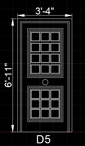
STEP 43:
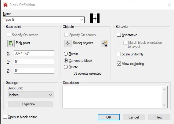
- Enter B in command box
- Enter Type 5 in NAME
- Pick the point
- Select the object
- Click CONVERT TO BLOCK
- Press OK
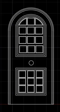
STEP 44:
- Enter CO in command box
- Copy D4 door
- Place it at required place
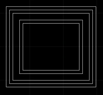
STEP 45:
- Delete the inner squares
- Enter O in command box
- Enter 2” as offset distance
- Enter O in command box
- Enter 1” as offset distance
- Press ENTER
STEP 46:
- Place those in the appropriate place
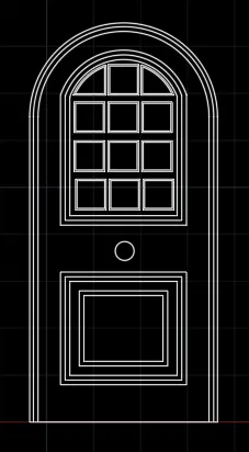
STEP 47:
- Enter DIMS in command box
- Select SYMBOLS AND ARROWS, Enter 5” as arrow size
- Select TEXT, Enter 5” as text height
- Enter DIML in command box and drag the dimensions.
- Enter DT in command box. Enter 6” as TEXT HEIGHT and 0 as TEXT ROTATION ANGE.
- Enter TEXT.
- Enter CO in command box. Copy the text and place it in another location.
- Enter TEXTEDIT in command box. Using this, editing in text can be done.
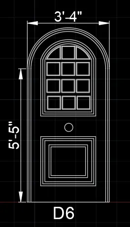
STEP 48:
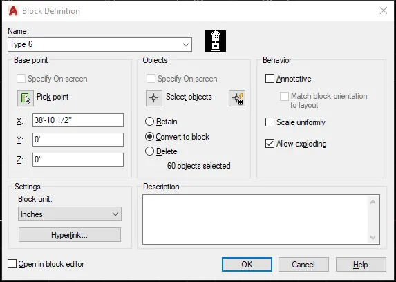
- Enter B in command box
- Enter Type 6 in NAME
- Pick the point
- Select the object
- Click CONVERT TO BLOCK
- Press OK
RESULT:
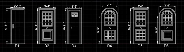
The Door type for residential building is created by lines using AutoCAD. The step-by-step procedure for creating door type for residential building is also explained. The Dimension is also entered in the diagram.
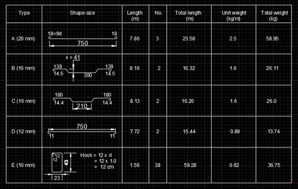
5)CREATING EACH SHAPE AS A BLOCK
AIM: To create each shape as a block using AutoCAD.
INTRODUCTION: Each shape as a block using AutoCAD is created by Lines. The procedure and result should be written after creating each shape as a block.
STEP 1:
- Open the AutoCAD software and click start Drawing tab.
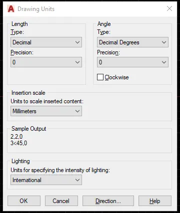
- Enter UNITS in command box.
- Select DECIMAL in TYPE, 0.0 in PRECISION and MILLIMETERS in UNITS TO SCALE INSERTED CONTENT. Press OK.
STEP 2:
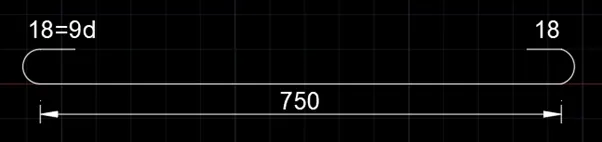
- Enter L in command box
- Enter 0,0 as first point
- Enter 750 as next point

STEP 3:
- Enter L in command box
- Click on the two sides
- Enter 18 as next point
- Enter 18 as next point
- Repeat it for other sides

STEP 4:
- Enter ARC in command box
- Create arcs on two sides

STEP 5:
- Delete two lines from both sides

STEP 6:
- Enter DIMS in command box
- Select SYMBOLS AND ARROWS, Enter 5 as arrow size
- Select TEXT, Enter 5 as text height
- Enter DIML in command box and drag the dimensions.
- Enter DT in command box. Enter 40 as TEXT HEIGHT and 0 as TEXT ROTATION ANGE.
- Enter TEXT.
- Enter CO in command box. Copy the text and place it in another location.
- Enter TEXTEDIT in command box. Using this, editing in text can be done.
STEP 7:
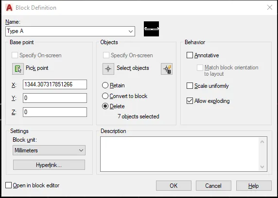
- Enter B in command box
- Enter Type A in NAME
- Pick point
- Select an object
- Click OK
STEP 8:
- Enter L in command box
- Enter 0,0 as first point
- Enter 300 as next point
- Press ENTER

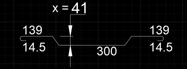
STEP 9:
- Enter L in command box
- Click on midpoint and enter 41
- Switch off ORTHOMODE
- Click on the corner
- Trace the 41mm line and place
- Repeat it on other side
STEP 10:
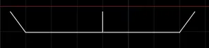
- Enter L in command box
- Click on the corner
- Enter 139 as next point
- Repeat it for other side

STEP 11:
- Enter L in command box
- Enter 14.5 as first point
- Enter 14.5 as next point
- Repeat it on other side

STEP 12:
- Enter ARC in command box
- Create arcs on both sides

STEP 13:
- Delete the lines on both sides

STEP 14:
- Enter DIMS in command box
- Select SYMBOLS AND ARROWS, Enter 5 as arrow size
- Select TEXT, Enter 5 as text height
- Enter DIML in command box and drag the dimensions.
- Enter DT in command box. Enter 40 as TEXT HEIGHT and 0 as TEXT ROTATION ANGE.
- Enter TEXT.
- Enter CO in command box. Copy the text and place it in another location.
- Enter TEXTEDIT in command box. Using this, editing in text can be done.
STEP 15:
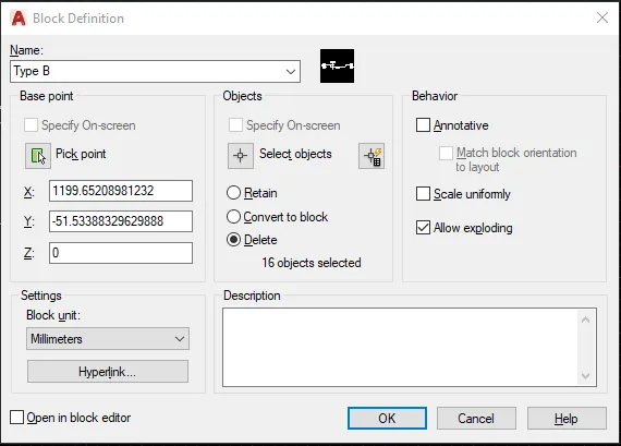
- Enter B in command box
- Enter Type B in NAME
- Pick point
- Select an object
- Click OK
STEP 16:
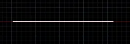
- Enter L in command box
- Enter 0,0 as first point
- Enter 210 as next point
- Press ENTER
STEP 17:
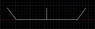
- Enter L in command box
- Click on midpoint and enter 41
- Switch off ORTHOMODE
- Click on the corner
- Trace the 41mm line and place
- Repeat it on other side
STEP 18:
- Enter L in command box
- Click on the corner
- Enter 180 as next point
- Repeat it for other side

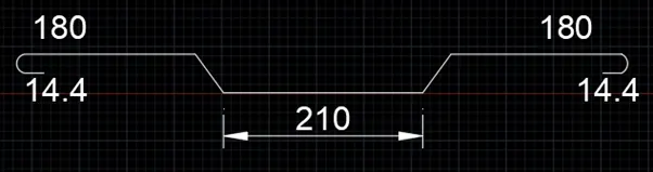
STEP 19:
- Enter L in command box
- Enter 14.4 as first point
- Enter 14.4 as next point
- Repeat it on other side

STEP 20:
- Enter ARC in command box
- Create arcs on both sides
- Delete the lines on both sides

STEP 21:
- Enter DIMS in command box
- Select SYMBOLS AND ARROWS, Enter 5 as arrow size
- Select TEXT, Enter 5 as text height
- Enter DIML in command box and drag the dimensions.
- Enter DT in command box. Enter 40 as TEXT HEIGHT and 0 as TEXT ROTATION ANGE.
- Enter TEXT.
- Enter CO in command box. Copy the text and place it in another location.
- Enter TEXTEDIT in command box. Using this, editing in text can be done.
STEP 22:
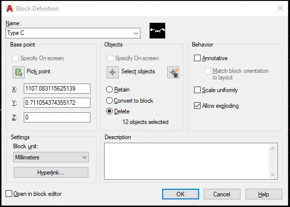
- Enter B in command box
- Enter Type C in NAME
- Pick point
- Select an object
- Click OK
STEP 23:
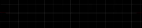
- Enter L in command box
- Enter 0,0 as first point
- Enter 750 as next point
- Press ENTER
STEP 24:
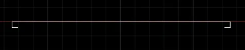
- Enter L in command box
- Enter 11 as first point
- Enter 11 as next point
- Repeat it another side
STEP 25:
- Enter ARC in command box
- Create arcs on both sides
- Delete the lines on both sides

STEP 26:
- Enter DIMS in command box
- Select SYMBOLS AND ARROWS, Enter 5 as arrow size
- Select TEXT, Enter 5 as text height
- Enter DIML in command box and drag the dimensions.
- Enter DT in command box. Enter 40 as TEXT HEIGHT and 0 as TEXT ROTATION ANGE.
- Enter TEXT.
- Enter CO in command box. Copy the text and place it in another location.
- Enter TEXTEDIT in command box. Using this, editing in text can be done.

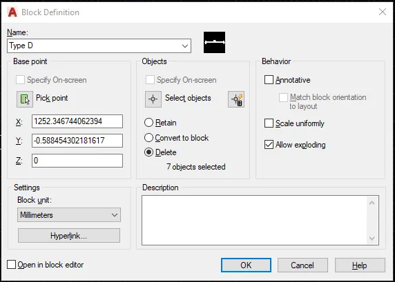
STEP 27:
- Enter B in command box
- Enter Type D in NAME
- Pick point
- Select an object
- Click OK
STEP 28:
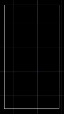
- Enter REC in command box
- Enter 23 as length
- Enter 43 as width
- Enter EXPLODE in command box
- Create individual lines
STEP 29:
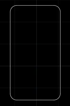
- Enter F in command box
- Enter 3 as radius
- Select the corner and make curve
STEP 30:
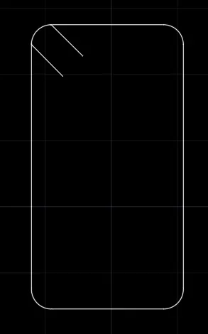
- Enter L in command box
- Switch off ORTHOMODE
- Click on the curve and enter 12 as first point
- Enter O in command box
- Enter 3 as offset distance
STEP 31:
- Enter DIMS in command box
- Select SYMBOLS AND ARROWS, Enter 5 as arrow size
- Select TEXT, Enter 5 as text height
- Enter DIML in command box and drag the dimensions.
- Enter DT in command box. Enter 40 as TEXT HEIGHT and 0 as TEXT ROTATION ANGE.
- Enter TEXT.
- Enter CO in command box. Copy the text and place it in another location.
- Enter TEXTEDIT in command box. Using this, editing in text can be done.
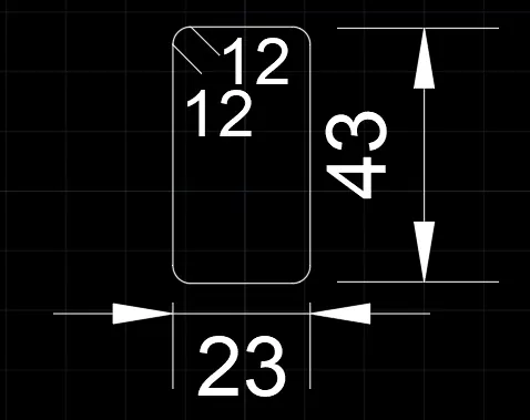
STEP 32:
- Enter B in command box
- Enter Type E in NAME
- Pick point
- Select an object
- Click OK
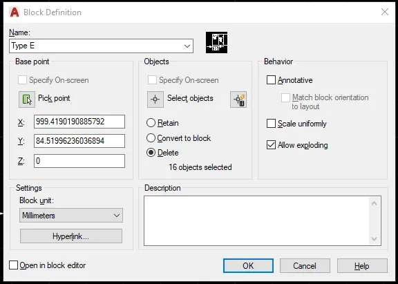
STEP 33:
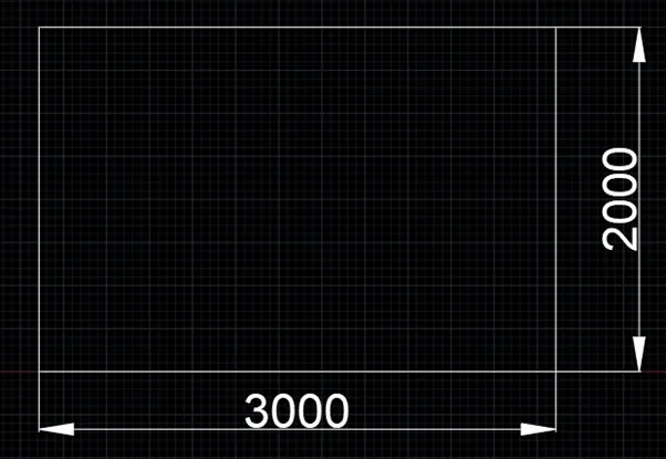
- Enter REC in command box
- Enter 3000 as length
- Enter 2000 as width
- Enter EXPLODE in command box
- Create individual lines
STEP 34:
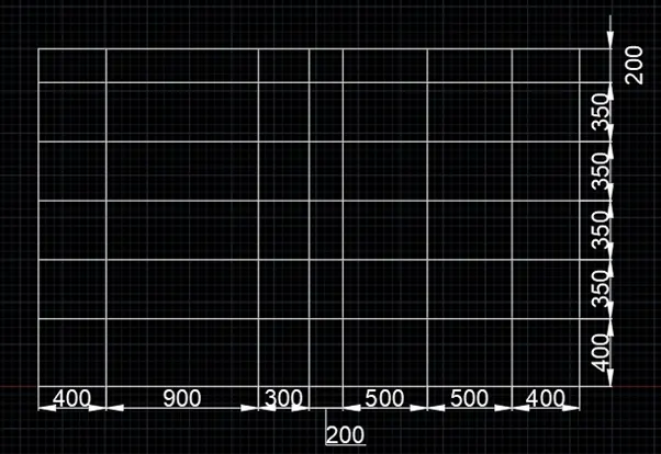
- Enter O in command box
- Enter 200, 350, 400, 900, 500 as offset distances
- Place it at appropriate places
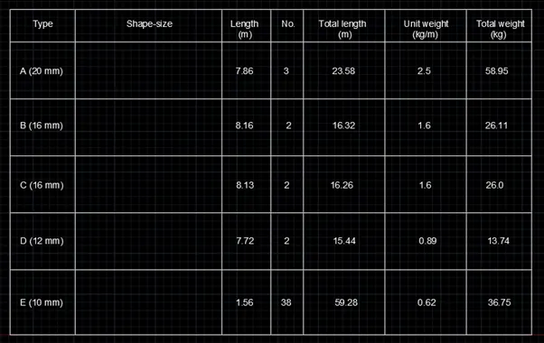
STEP 35:
- Enter DT in command box
- Enter 52 as text height
- Enter the text in the table
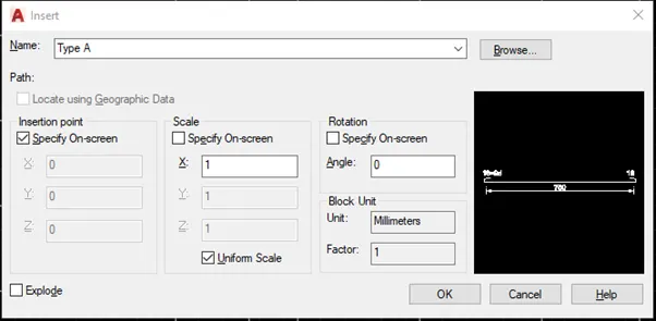
STEP 36:
- Enter I in command box
- Select Type A from the dropdown
- Insert in the table
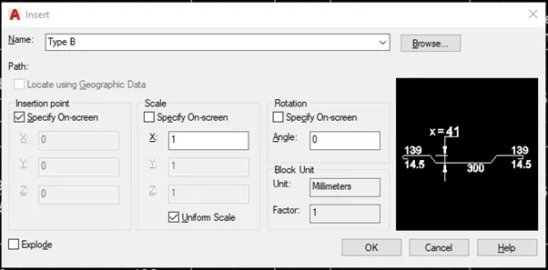
STEP 37:
- Enter I in command box
- Select Type B from the dropdown
- Insert in the table
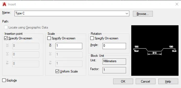
STEP 38:
- Enter I in command box
- Select Type C from the dropdown
- Insert in the table
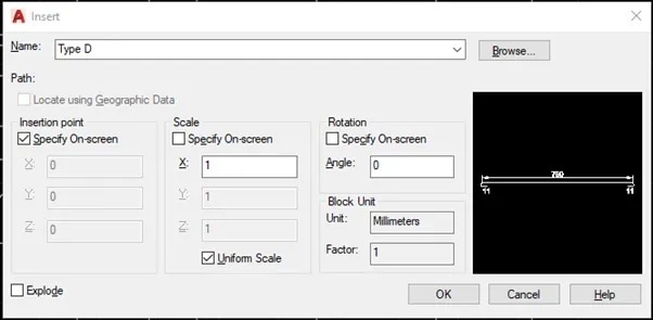
STEP 39:
- Enter I in command box
- Select Type D from the dropdown
- Insert in the table
STEP 40:
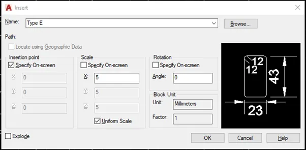
- Enter I in command box
- Select Type E from the dropdown and enter 5 as scale
- Insert in the table
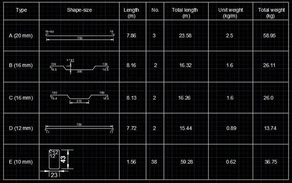
STEP 41:
- Insert all the items in the table
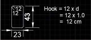
STEP 42:
- Enter DT in command box
- Enter 52 as text height
- Enter the text
RESULT:
Each shape as a block is created by lines using AutoCAD. The step-by-step procedure for creating each shape as a block is also explained. The Dimension is also entered in the diagram.