Creating Bar Bending schedule, Different Door types, and Creation of standard drawing templates using AutoCad
Creation of Templates in AutoCAD
Aim:
Create a template containing details of the type of drawing, architect, date, designer, drafter, title, sheet number, drawing number, and all other general details of drawing which makes it easy to identify and unique.
Procedure:
- Open AutoCAD and type CTRL+N for new workspace
- Type UNIT and set input system as metric with input unit as meter
- Type LAYER and creates layers for a different types of objects in drawing
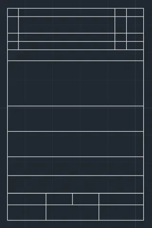
Drawing of templet body (Vertical)
- Draw a horizontal LINE of 2.47 m length at base
- OFFSET this base line by 0.3, 0.2, 0.3, 0.3, 0.46, 0.46, 0.82, 0.2, 0.15, 0.15, 0.3 and 0.15 m successively and vertically
- Use LINE to draw sidelines to make it closed
- For date section, OFFSET by 0.31 and 0.21 on right side wall on top two 2 sections
- For bottom sections, OFFSET vertical line by 0.7, 0.48, 0.48, and 0.48 for sections as shown in the drawing
Inserting texts in the template (Vertical)
- Use MTEXT to type the texts in the designated blocks
- Use the COPY command to shift the text block to the location where text is to be written
- Increase the thickness of the right wall and bottom wall using LWEIGHT command
- Assign LAYER to each part as shown in the drawing
- To make the block, type BLOCK, and select base point and object to make it block with the name “Vertical_Titleblock”
Results of Vertical Templet:
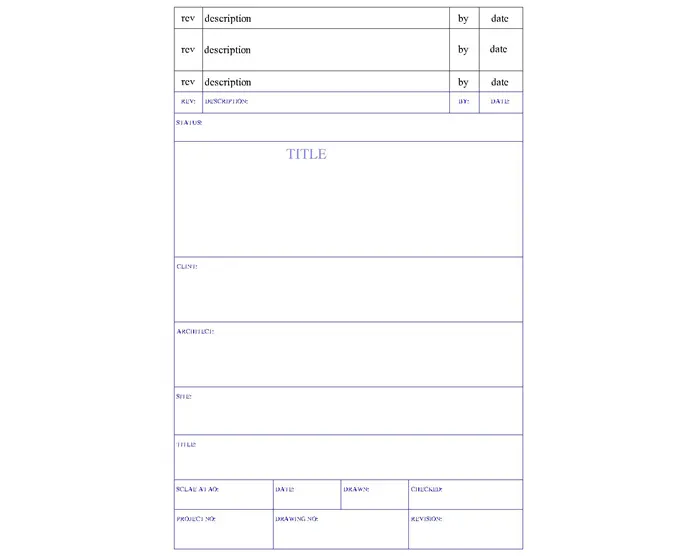
Drawing of templet body (Horizontal)
- Use LINE to draw the horizontal line for a baseline
- OFFSET the baseline by 0.4 two times
- Use OFFSET and TRIM command to make all the squares
Inserting texts
- Use the MTEXT command to type the texts at the various locations with the desired transparency
- To make the block, use the BLOCK command and insert base point and object to make it block
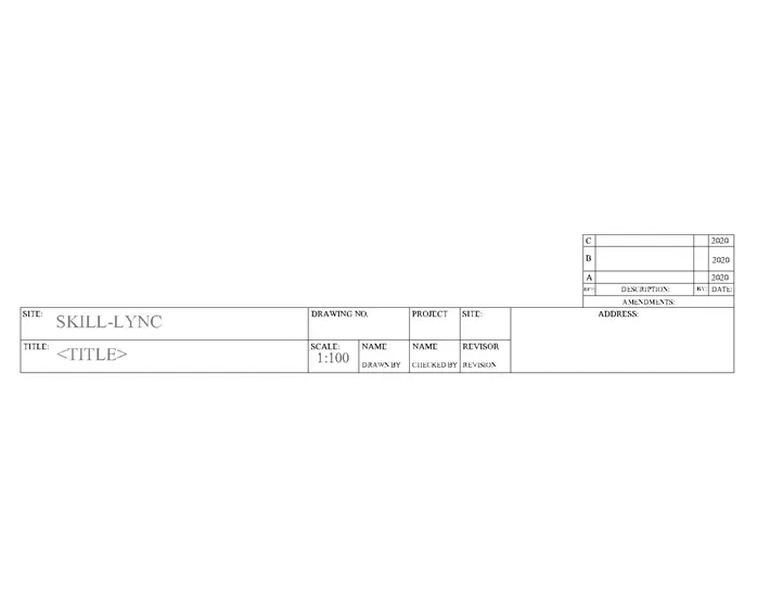
Results of Horizontal Templet:
Drawing of Doors
Aim:
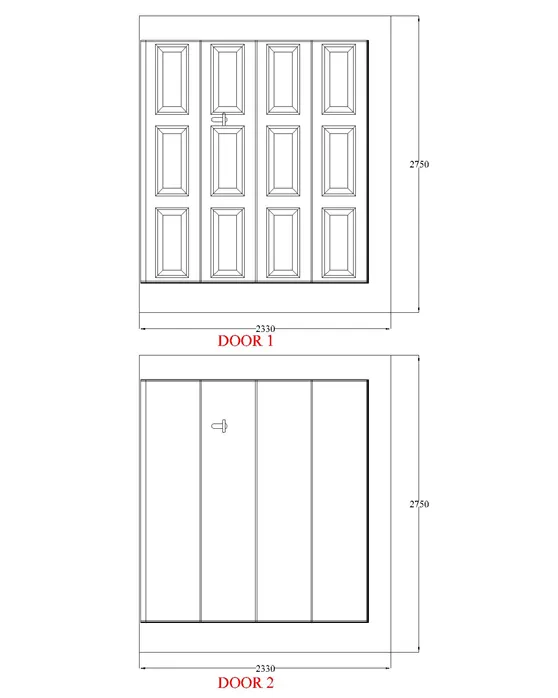
Drawing of door 1 and door 2 for the warehouse using various commands of AutoCAD with given dimensions in the challenges
Procedure:
- Open AutoCAD and type CTRL+N for new workspace
- Type UNIT and set input system as metric with input unit as meter
- Type LAYER and creates layers for different types of objects in the drawing
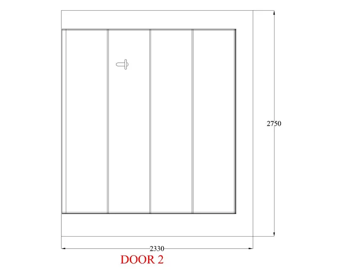
Drawing of door 2
- Draw a LINE of 2120 mm and OFFSET it by 3mm two times and 12 mm one time in order for the bottom line
- Draw a 2250 mm length LINE on the left end and OFFSET for suitable distance to make door marking in between as shown in the drawing
- Draw the top LINE of the door and OFFSET it downward side as drawn here
- Make RECTANG of 2330x 2750 mm around the gate
- Use LINE and TRIM to draw the doorknob as shown
- Use DIMLINE and DIMCONT to draw all the dimensions
- Use MTEXT to place texts
- Use BLOCK to make an integrated object
Result for door 2:
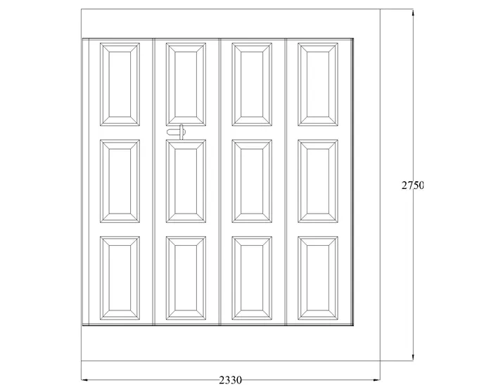
Drawing of Door 1
- Door 2 and Door 1 have outside frame structures same as per shown drawing.
- For drawing of panels, use RECTANG and LINE commands
- Use the TRIM command to remove excess lines in the object
- COPY the one panel and place it at an equal distance as shown in the drawing
Result of door 1:
Result:
Creating of Symbols Legend
Aim:
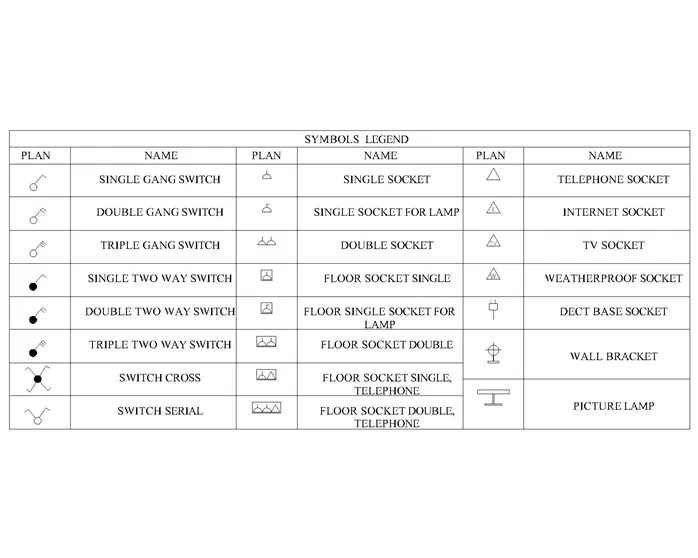
Legends are an inseparable part of the drawing as this gives information about each object in the drawing, legends need to be drawn clearly and separately in tabular format. This exercise creates the drawing of symbols legend as shown in the drawing
Procedure:
- Open AutoCAD and type CTRL+N for new workspace
- Type UNIT and set input system as metric with input unit as meter
- Type LAYER and creates layers for different types of objects in the drawing
Drawing of table
- Use the TABLE command and create a table of 10 rows and 6 columns. Adjust the rows and tables according to the given format
- Use MTEXT to type names of various legends
- Use a combination of LINE, COPY, ROTATE, CIRCLE, TRIM, ARC, OFFSET, RECTANG, FILLET, and HATCH to draw the symbols of the table as shown in the drawing
Results:
Drawing of doors
Aim:
Doors are the opening for entrance or exit in any structure. Residential buildings do have many types and sizes of doors. In this exercise, 6 different types of doors is drawn.
Procedure:
- Open AutoCAD and type CTRL+N for new workspace
- Type UNIT and set input system as architectural with input unit as inches
- Type LAYER and creates layers for different types of objects in the drawing
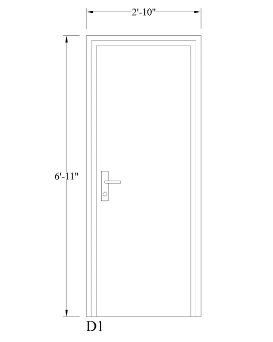
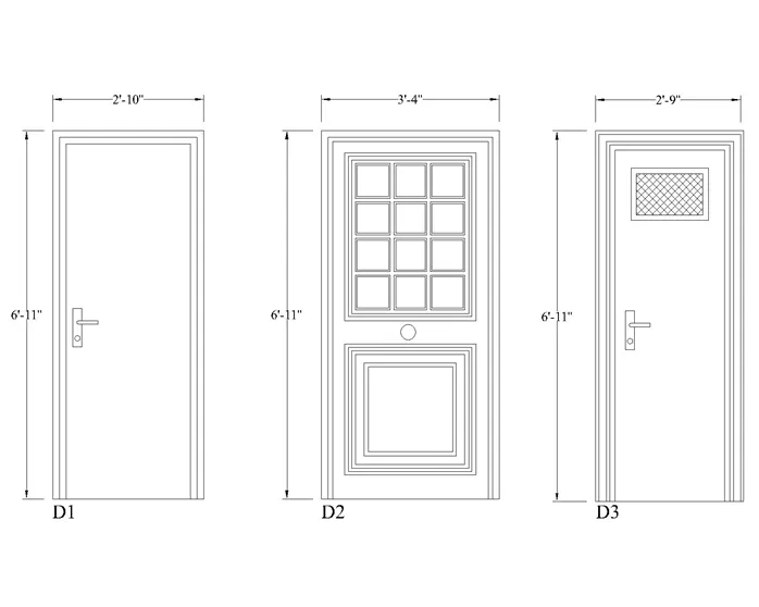
Drawing of D1
- Draw a RECTANG of 2’10”x6’11”
- Make an OFFSET of 1.5” from both and topside
- Use LINE and CIRCLE to draw the knob of the door
- Use the BLOCK command to make it block
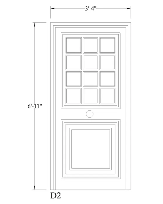
Drawing of D2
- Draw a RECTANG of 3’4”x6’11”
- Make an OFFSET of 1.5” and 1” from both and topside
- Use RECTANG, OFFSET and TRIM to draw 3 rectangles around top panels
- Use RECTANG, OFFSET to draw the panel and again COPY the one panel to place symmetrically as shown in the drawing
- Use CIRCLE to draw knob in between the top and bottom panels
- Use RECTANG and OFFSET to draw the bottom panels
- Use the BLOCK command to make it block
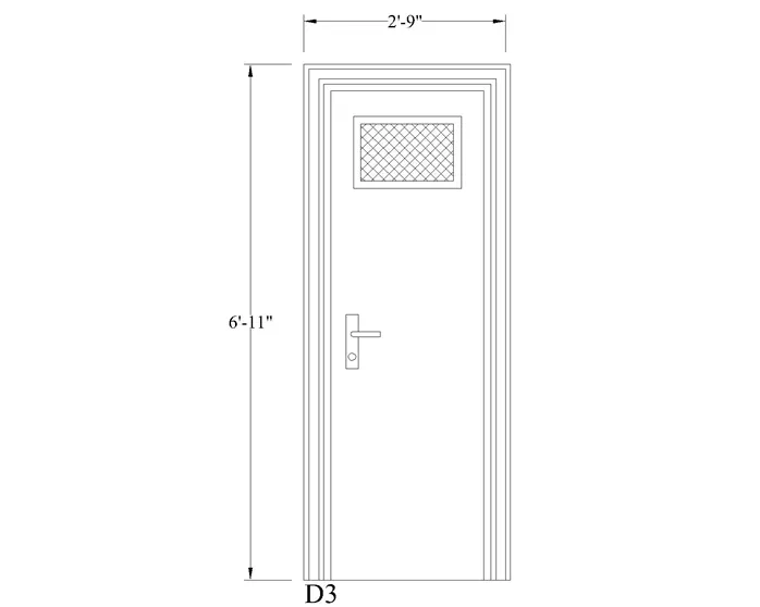
Drawing of D3
- Draw a RECTANG of 2’9”x6’11”
- Make an OFFSET of 1.5” and 1” from both and topside
- Use RECTANG, OFFSET to draw the rectangular panel on the top of the door
- Use the HATCH command to fill in the panel as shown in the drawing
- Use the BLOCK command to make it block
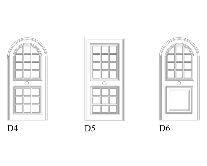
Drawing of D4, D5, and D6
- D4, D5, and D6 have similar geometry except at the top for the outer frame. Panels of the drawing are all in a rectangular shape as shown
- Assuming the height of D4, D5, and D6 as 6’11” as in the previous example
- Assuming width of D4, D5, and D6 as 3’4”
- Draw a LINE at the bottom for the length of 3’4”
- Draw a vertical LINE and OFFSET it by 1.5” and 1” on both sides
- For the top in D5 and D6 arc, use the ARC command and draw the semicircle
- For panels, Use RECTANG, OFFSET, TRIM, CIRCLE, ARC, FILLET to draw as shown in the drawing
- Use the BLOCK command to make this object into a block for future reference with the name of “door_D4” and so on
Results:
Creating of Bar Bending Schedule
Aim:
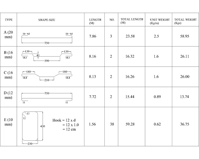
For keeping a tab on the accurate steel requirement with shape and lengthwise, a bar bending schedule is generally prepared at the site. Bar bending schedule contains bar shape, length, size, weight etc. for calculation and cutting bending purposes.
Procedure:
- Open AutoCAD and type CTRL+N for new workspace
- Type UNIT and set input system as metric with input unit as mm
- Type LAYER and creates layers for different types of objects in the drawing
Drawing of table
- Use TABLE command to draw the table with 6 rows and 7 columns and rows are adjusted as shown in the drawing
- Use MTEXT to type in various texts like heading, attributes, etc.
- Use LINE, COPY, MIRROR, MOVE, OFFSET, EXTEND, TRIM, ARC, DIMLIN, MTEXT to draw all the shapes of the bars as shown in the drawing
Conclusion:
This exercise contains various types of drawing like – doors, bar bending schedule, symbol legends, etc. which all are important for any drawing. In-depth, knowledge of drawing is required. In all of this exercise, we used a number of commands like – LINE, COPY, MIRROR, OFFSET, TRIM, MOVE, FILLET, MTEXT, QLEADER, DIMLIN, DIMCONT, TABLE, etc. Continuous use of these exercises gives us a very well command and makes it efficient for the architecture.