Creating Bar Bending schedule, Different Door types, and Creation of standard drawing templates using AutoCad
AIM : 1. Creating Bar Bending schedule, Different Door types, and Creation of standard drawing templates using AutoCad.
Introduction: In this challenge i have draft the above meationed drawing i.e, Bar Bending schedule, Different Door types, and Creation of standard drawing templates, using AutoCad. here in this challange i have attached all the drawings in a image format and with the proper procedure as possible.
The comman commands which are used in this challange are discussed below
Selecting of Tools:
- Line: Ribbon< Home< Line, Command: Line or L, Home< Draw< Line.
- Polyline: Ribbon< Home< Polyine, Command: polyline or pl, Home< Draw< polyline.
- Rectangle: Ribbon< Home< rectangle, Command: rectangle or rec, Home< Draw< rectangle.
- Ploygon: Ribbon< Home< Ploygon, Command: Ploygon or pol, Home< Draw< Ploygon.
- Circle: Ribbon< Home< Circle, Command: Circle or C, Home< Draw< Circle.
- Fillet: Ribbon< Home< Fillet, Command: Fillet or F, Home< modify< Fillet.
- Chamfer: Ribbon< Home< Chamfer, Command: Chamfer or cha, Home< modify<Chamfer.
- Move: Ribbon< Home< move, Command: move or M, Home< modify<Move.
- Copy: Ribbon< Home< Copy, Command: Copy or co, Home< modify<Copy.
- TRIM: Ribbon< Home< trim, Command: TRIM or TR, Home< modify
Question 1:
1. Create the templates as shown in Figures. Take the size of the title block as per industry standards or you can assume it as per the size of the paper. Use text and attributes wherever required. After creating the title block you need to save it as a block with names: Custom1_titleblock and Custom2_titleblock, respectively.
ANS: Here i have attached the image which i have made in autocad 2019,
Template 1>
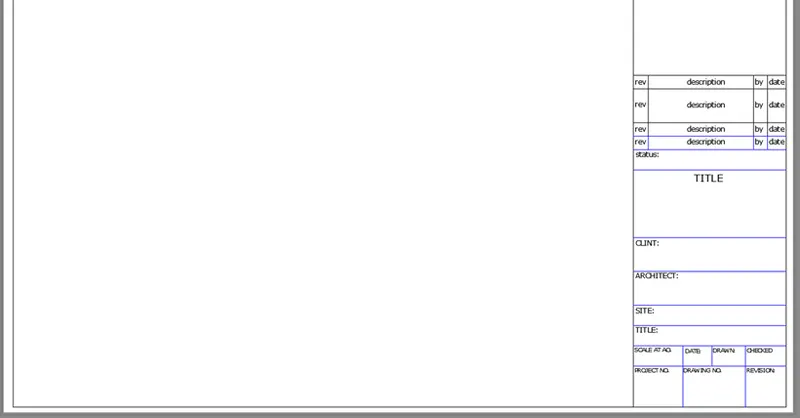
Procedure:
- Start auto cad 2019 app select new drawing option and set the screen.
- Give a command startup and press enter select option 1 and press enter
- Further give a command limmax and set the limit by 50' by 50' press enter
- This complets the setup of autocad drawing now select layout option which is at the bottom
- Now give a command layout and select template and select the appropriate template if available
- In this case we need to create a new template by using line tool
- Select a rectangal tool and draw a rectangal at the layout boundary as shown in the figure
- Give a offset of 1 inch internally as shown in the figure
- Select a line command and draw a appropriate line as shown in the figure
- Draw tables by using the same command different tables as shown in the figure of assumed sizes
- Use mtext command and write appropriate names which are given in the question and save the file
- This complete the creation of template
Template 2>
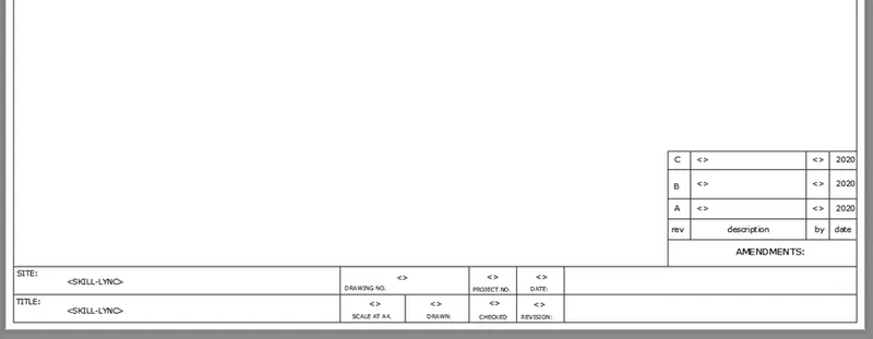
Procedure:
- Start auto cad 2019 app select new drawing option and set the screen.
- Give a command startup and press enter select option 1 and press enter
- Further give a command limmax and set the limit by 50' by 50' press enter
- This complets the setup of autocad drawing now select layout option which is at the bottom
- Now give a command layout and select template and select the appropriate template if available
- In this case we need to create a new template by using line tool
- Select a rectangal tool and draw a rectangal at the layout boundary as shown in the figure
- Give a offset of 1 inch internally as shown in the figure
- Select a line command and draw a appropriate line as shown in the figure
- Draw tables by using the same command different tables as shown in the figure of assumed sizes
- Use mtext command and write appropriate names which are given in the question and save the file
- This complete the creation of template
Question 2:
Create the doors type for warehouse as shown in the Figure. You need to create each door type as per standard size or given dimensions. Create the blocks of this door type after creating them.
ANS: Here i have attached the image which i have made in autocad 2019,
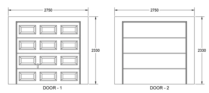
Procedure:
- Draw a rectangle of dimension 2330, 2750.
- Explode the rectangle by using the EX as shown in the figure.
- Give a offset of 300 in two sides and offset of 200 at topside.
- Use trim command and trim all the extra lines.
- Use divide command and divide sides in four parts.
- Use XL command and mark the points horizontally.
- Again use the divide command and divide the upper side in three parts.
- Trim the extra lines projecting outside the box.
- Use offset of 10mm at newly drawn lines.
- Use offset 15mm at the exterior lines.
- Use fillet command and join the extra lines.
- Draw the hinge as shown in the figure.
- Draw the panel design as shown in the question with assumed dimension.
- Use copy option and select the base point, than copy the rectangular panel as shown in the figure.
- Use Mtext command and type door 1 and placed it below the created door.
Question 3:
Create each symbol as a block with the name given in the legend. After creating the blocks arrange them in the legend as shown in the Figure.
ANS: Here i have attached the image which i have made in autocad 2019,
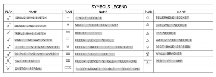
Procedure:
- For creation the legend which is shown in the question by using block command
- Create a circle of appropirate size and draw a line along with it as shown in the figure
- select the created circle and block it by using the command B
- In which select a pick point as circle centre and press enter then select the whole image now give the name as single gang switch as shown in the figure
- use the same procedure for creating different blocks which are shown in the figure by using the same method
- Now create a table by using line tool and rectangle tool as shown in the figure
- Now place the block serial wise which already has created in a sequence as shown in the figure
- Go to the robbon panel select the insert option in which further select feild option which is shown in the ribbon panel
- Now select the option named object in the feild panel and select the block
- which i have created and select the name option and press enter
- Now the name displayed should be kept in front of the block which is created
- Do similar with the other blocks too.
Question 4:
Create the door type for residential building as a block. Save the name of the blocks as type. Use given dimensions or assume dimensions as per industry standards.
ANS: Here i have attached the image which i have made in autocad 2019,
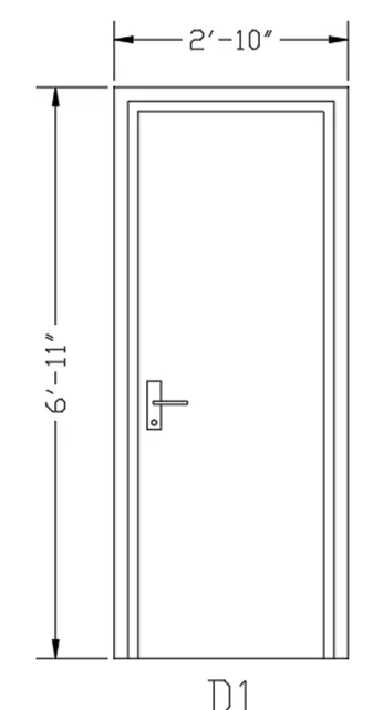
Procedure:
- Draw a rectangle of dimension 2330, 2750.
- Explode the rectangle by using the EX as shown in the figure.
- Give a offset of 300 in two sides and offset of 200 at topside.
- Use trim command and trim all the extra lines.
- Use divide command and divide sides in four parts.
- Use XL command and mark the points horizontally.
- Again use the divide command and divide the upper side in three parts.
- Trim the extra lines projecting outside the box.
- Use offset of 10mm at newly drawn lines.
- Use offset 15mm at the exterior lines.
- Use fillet command and join the extra lines.
- Draw the hinge as shown in the figure.
- Draw the panel design as shown in the question with assumed dimension.
- Use copy option and select the base point, than copy the rectangular panel as shown in the figure.
- Use Mtext command and type door 1 and placed it below the created door.
Procedure:
- Use rec command and draw a rectangle of size 2’10” by 6’11” as of standard size
- Trim the bottom line by using TR option as a create problem use line command and draw a bottom line again
- Use offset command and give a offset of 2 inch to the upper frame like structure.
- Similarly again use offset command and give a offset of 1 inch by selecting the inner frame press enter
- For creating the door lock handle by using rectangle of dimension 2 inch by 8 inch and press entre.
- Draw a rectangle by using REC command of dimension 6 inch 0.5 inch and press entre.
- move this rectangle by using M command and move it above the recently created rectangle.
- Create a circle by using C command just below the horizontal rectangle as shown in the figure.
- Use trim by using command TR erase the intersected line in between the horizontal rectangle
- Move the whole set of lock arrangement using the command M to the created door panel as shown in the figure.
- Use mtext command to write the type of door i.e., D1 and place it just below the created door panel.
- Use linear dimension command at top end side of the door panel
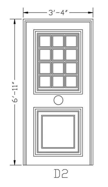
- procedure:
- Draw a rectangle of dimension 2330, 2750.
- Explode the rectangle by using the EX as shown in the figure.
- Give a offset of 300 in two sides and offset of 200 at topside.
- Use trim command and trim all the extra lines.
- Use divide command and divide sides in four parts.
- Use XL command and mark the points horizontally.
- Again use the divide command and divide the upper side in three parts.
- Trim the extra lines projecting outside the box.
- Use offset of 10mm at newly drawn lines.
- Use offset 15mm at the exterior lines.
- Use fillet command and join the extra lines.
- Draw the hinge as shown in the figure.
- Draw the panel design as shown in the question with assumed dimension.
- Use copy option and select the base point, than copy the rectangular panel as shown in the figure.
- Use Mtext command and type door 1 and placed it below the created door.
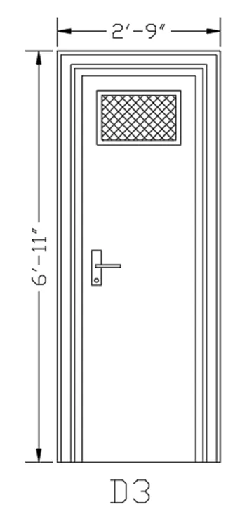
Procedure:
- Use rec command and draw a rectangle of size 2’10” by 6’11” as of standard size
- Trim the bottom line by using TR option as a create problem use line command and draw a bottom line again
- Use offset command and give a offset of 2 inch to the upper frame like structure.
- Similarly again use offset command and give a offset of 1 inch by selecting the inner frame press enter
- For creating the door lock handle by using rectangle of dimension 2 inch by 8 inch and press entre.
- Draw a rectangle by using REC command of dimension 6 inch 0.5 inch and press entre.
- move this rectangle by using M command and move it above the recently created rectangle.
- Create a circle by using C command just below the horizontal rectangle as shown in the figure.
- Use trim by using command TR erase the intersected line in between the horizontal rectangle
- Move the whole set of lock arrangement using the command M to the created door panel as shown in the figure.
- Use mtext command to write the type of door i.e., D1 and place it just below the created door panel.
- Use linear dimension command at top end side of the door panel.
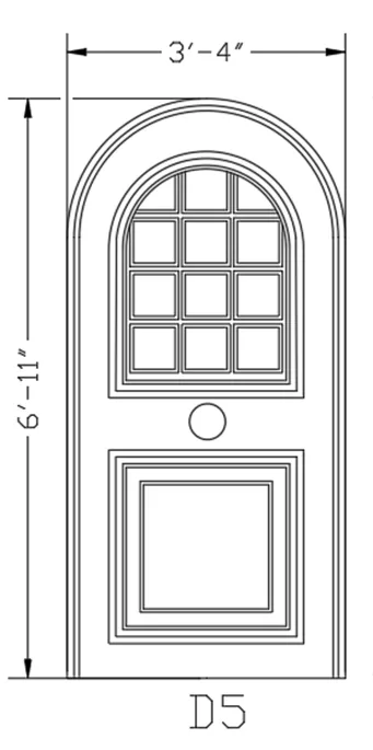
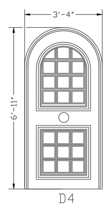
Procedure:
- Draw a rectangle of dimension 2330, 2750.
- Explode the rectangle by using the EX as shown in the figure.
- Give a offset of 300 in two sides and offset of 200 at topside.
- Use trim command and trim all the extra lines.
- Use divide command and divide sides in four parts.
- Use XL command and mark the points horizontally.
- Again use the divide command and divide the upper side in three parts.
- Trim the extra lines projecting outside the box.
- Use offset of 10mm at newly drawn lines.
- Use offset 15mm at the exterior lines.
- Use fillet command and join the extra lines.
- Draw the hinge as shown in the figure.
- Draw the panel design as shown in the question with assumed dimension.
- Use copy option and select the base point, than copy the rectangular panel as shown in the figure.
- Use Mtext command and type door 1 and placed it below the created door.
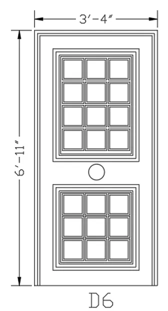
Procedure:
- Use rec command and draw a rectangle of size 2’10” by 6’11” as of standard size
- Trim the bottom line by using TR option as a create problem use line command and draw a bottom line again
- Use offset command and give a offset of 2 inch to the upper frame like structure.
- Similarly again use offset command and give a offset of 1 inch by selecting the inner frame press enter
- For creating the door lock handle by using rectangle of dimension 2 inch by 8 inch and press entre.
- Draw a rectangle by using REC command of dimension 6 inch 0.5 inch and press entre.
- move this rectangle by using M command and move it above the recently created rectangle.
- Create a circle by using C command just below the horizontal rectangle as shown in the figure.
- Use trim by using command TR erase the intersected line in between the horizontal rectangle
- Move the whole set of lock arrangement using the command M to the created door panel as shown in the figure.
- Use mtext command to write the type of door i.e., D1 and place it just below the created door panel.
- Use linear dimension command at top end side of the door panel.
Question 5:
Create each shape as a block as shown in the Figure. Save the block and insert them on the table as shown in the Figure.
ANS: Here i have attached the image which i have made in autocad 2019,
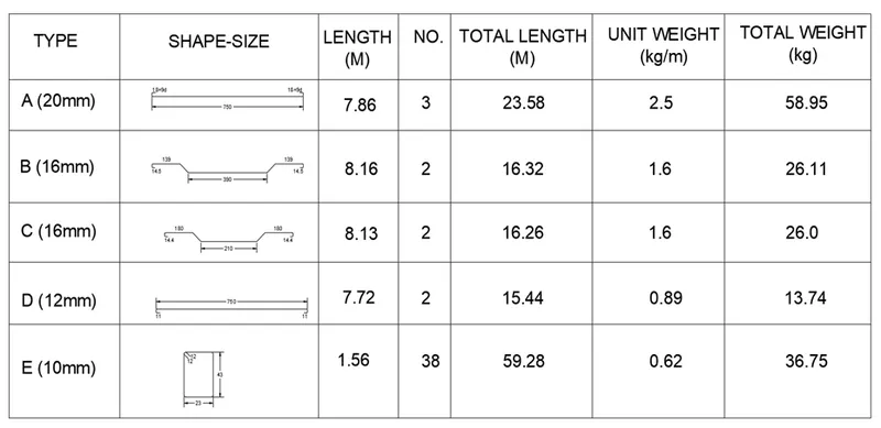
Procedure:
- Draw a table as shown in the figure by using line tool
- Use line tool to draw rows and column as shown in the figure
- To draw the links and stirrup take a line command adn draw a line of size 750mm and draw side links of 18mm at both end of the line
- Use fillet command with a radius of 5mm join both the lines at the end
- Do similar method to draw all the links which are shown in the above image
- For drawing the stirrup draw a rectangal by using REC command of size 230mm * 430mm as shown in the figure
- Use fillet option and with radious of 35mm at all the four sides
- Do similar method to draw all the links which are shown in the above image
- Use Mtext command and type the anmotations which are shown in the above image
- Use CO command and copy the text at different places as shown in the figure
- Use text edit option in order to edit all the text which are copied in the table
- Use the dimlinear command and provide dimension to the newly created links and stirrups as shown in attached image.