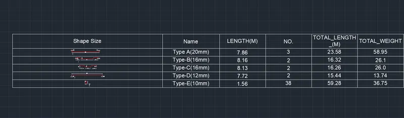
Creating Bar Bending schedule, Different Door types, and Creation of standard drawing templates using AutoCad
1.
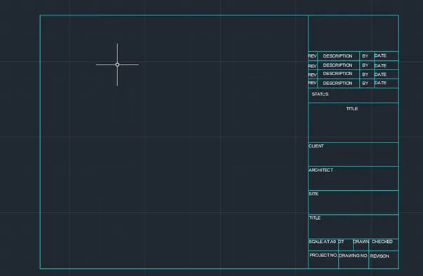
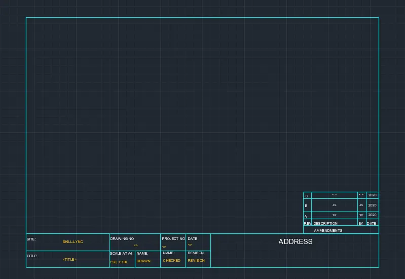
Aim:- To Create the templates as shown in Figures. Take the size of the title block as per industry standards or you can assume it as per the size of the paper. Use text and attributes wherever required. After creating the title block you need to save it as a block with names: Custom1_titleblock and Custom2_titleblock, respectively.
Procedure:
- Give the Command of Limax and Press Enter the Suitable Values and Press Enter
- Select the Layers from the Ribbon tab and Create a New Layers By Clicking a New Layer to Crete a New Layer
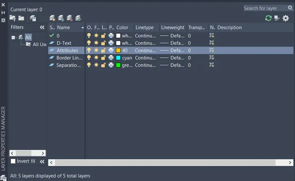
- Select the Borders to Current Layer
- Give the Command of Rec and Specify the starting point Select the Dimensions from the Command Bar and Give the Length as 1189 and width as 841 Press Enter
- Give the Command of X plod and Select the Object and Press Enter
- Select the Right Side Vertical Line Give the Offset Command and Give the Offset Length as Suitable Press Enter
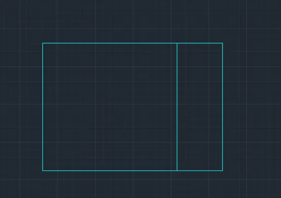
- Now Give the Horizontal Offsite Lines as Suitable offset Distance Press Enter
- Trim the Unnecessary Lines Press enter
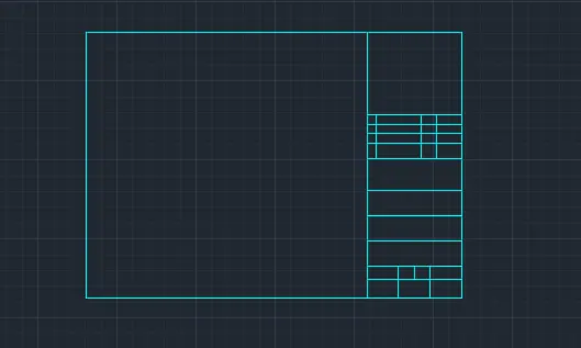
- Change the Layer to D-Text and Press Enter
- Give the Text From the Selection of Single Line text in Annotative tab From the Ribbon Tab and Give the Height and Angle and Give the text and Press Enter
- Repeat the Procedure until Requirement Complition
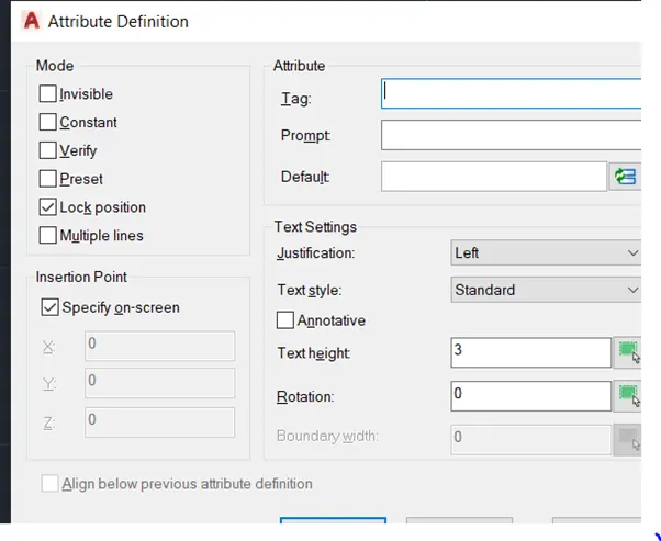
- Now Give the Command of ATT and Press Enter to Open a Window
- Set Mode as Lock Position
- Set Tag as Project No
- Set Prompt as What is the tag
- Set Default as requirement and Press enter
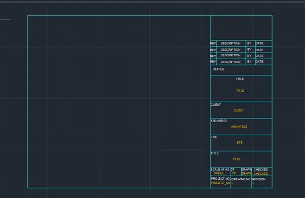
- Repeat the Same Procedure to ass Attributes
- Final Result Shown as below
- Give the Command of B and press enter to Shows a Window
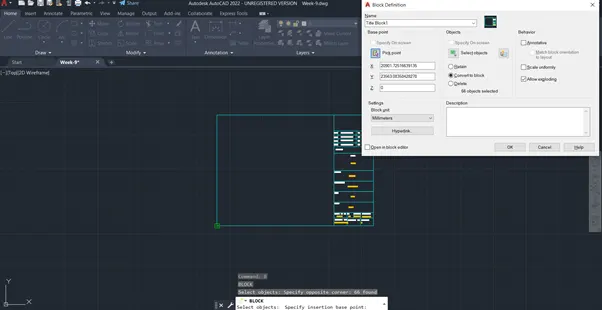
- Give the Block Name and Select the object and select Pick up Point Press Enter to Open a window
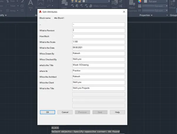
- Press Ok to Final Result Below
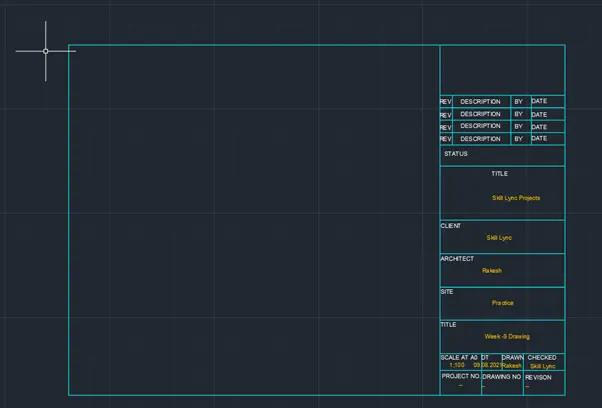
Creating custom Title Block-2
- Change the Current Layer to Out Line Press Enter
- Give the Command of Rec and Press Enter Specify the Starting Point and Select the Dimensions From the Ribbon tab and Give the Length and Width Press Enter (420X297)
- Select the Rectangle Give the Command of X plod Press Enter
- Give the offset Command and Offset the Line Where its Required and Press Enter
- Trim the Unnecessary Lines By Using the Trim Command into Command Bar and Press Enter
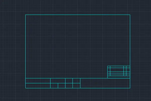
- Change the Layer to D-Text and Press Enter
- Give the Text From the Selection of Single Line text in Annotative tab From the Ribbon Tab and Give the Height and Angle and Give the text and Press Enter
- Repeat the Procedure until Requirement
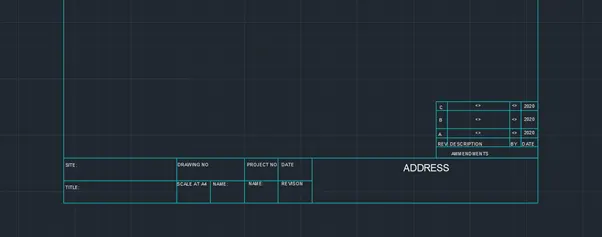
- Now Give the Command of ATT and Press Enter to Open a Window
- Set Mode as Lock Position
- Set Tag as Project No
- Set Prompt as What is the tag
- Set Default as requirement and Press enter
- Repeat the Same Procedure to ass Attributes
- Give the Command of B and press enter to Shows a Window
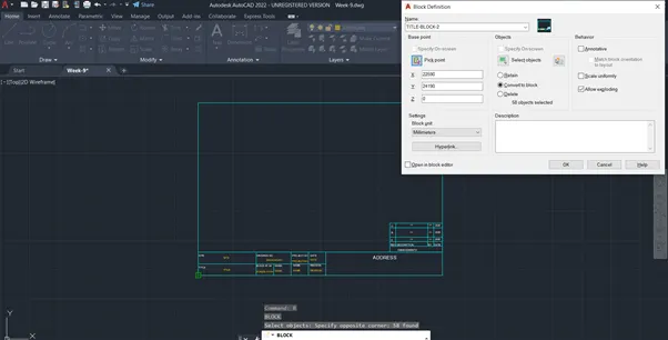
- Give the Block Name and Select the object and select Pick up Point Press Enter to Open a window
-
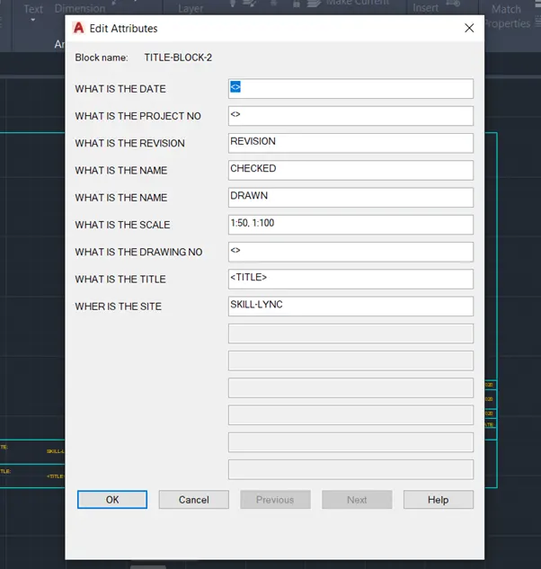
- Press Ok to Final Result Below
-
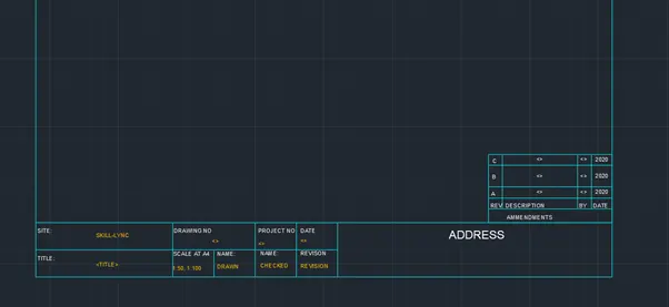
Result:-
- TITLE-BLOCK-1
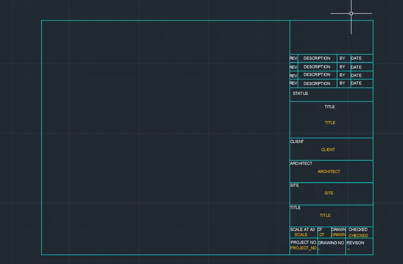
- TITLE-BLOCK-2
2.
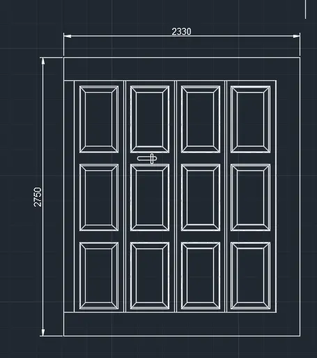
Aim:- To Create the doors type for warehouse as shown in the Figure. You need to create each door type as per standard size or given dimensions. Create the blocks of this door type after creating them.
Procedure:
- Give the Comamnd of Rec and Press Enter Specify the Starting Point and Select the Dimension and Give the Length and Breadth as Per Given
- Give the Comamnd of Copy in Command Bar Press Enter Select the Object and Specify the Point and Press Enter
- Select the Object and Give the Command of Xplode Press Enter
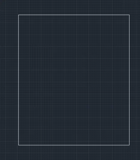
- Select the Bottom of Horizontal line Give the Command of Offset and Press Enter Give the Offset distance as 230 and Press Enter Give the Offset to Top
- Select the Top of Horizontal line Give the Command of Offset and Press Enter Give the Offset distance as 230 and Press Enter Give the Offset to Bottom
- Select the Right Side of Vertical line Give the Command of Offset and Press Enter Give the Offset distance as 230 and Press Enter Giver the Offset to Left Side
- Select the left Side of The Vertical Line and assume the Offset Distance as Per Given Diagram
-
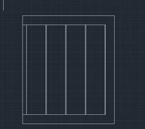
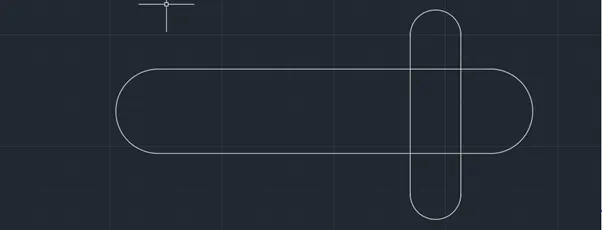
- Draw a Frame by Using Rectangle Command Specify the Point In side of the door Frame assume the Dimensions and Give the Length and Breadth Press Enter
- Repeat the Procedure Untill Complition of Inner Panels
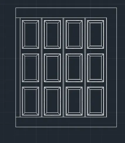
- Draw a Door Handle by Using Rectangle Command Specify the Point In side of the door Frame assume the Dimensions and Give the Length and Breadth Press Enter
- Draw a another Rectangle Perpendicular to Previous Rec and Press Enter
- Give the Command of Circle Select Two Points and Specify the End Points of Rec and Press Enter
- Trim the unnecessary lines press Enter
-
- Its Shows Like Below
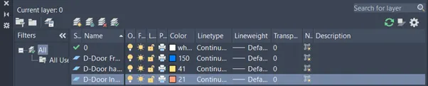
- Select a new Layer From the Ribbon tab to Requirements
- Change the Objects to Suitable Layers and Press Enter
- Give the Hattch Command Specify the Points Where its Required and Press Enter and Give the Suitable Scale Press Enter
-
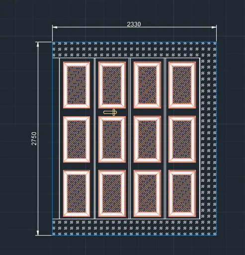
- To Create a Block to Give the Command of B and Select the Object and press Enter
- Give the name was Door-1 and Selct the Pick Point and Press Ok
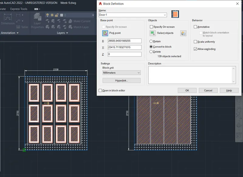
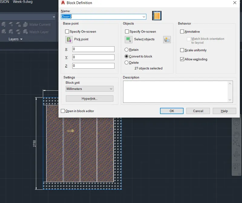
- To Create a Block to Give the Command of B and Select the Object and press Enter
- Give the name was Door-2 and Selct the Pick Point and Press Ok
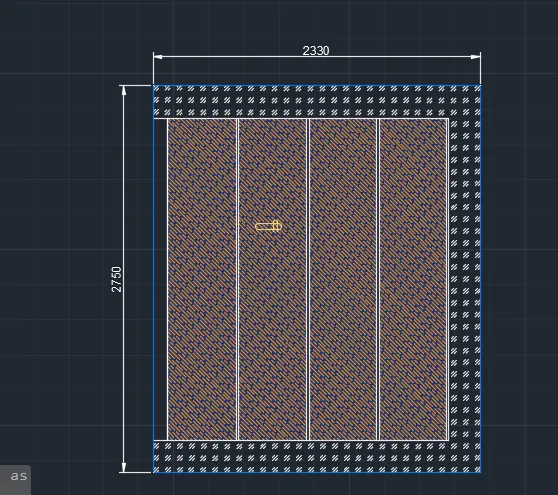
Result:-
Door-1
Door-2
3.
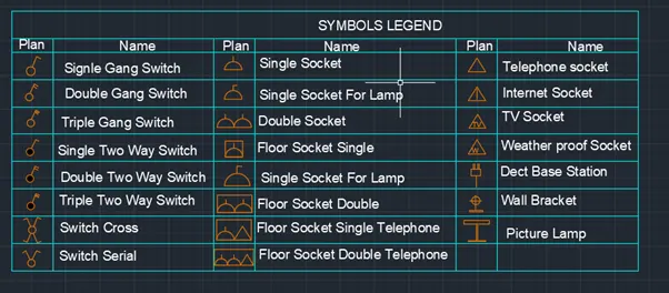
Aim:- To Create the Blocks and Legends as Shown in Figure After creating the blocks arrange them in the legend as shown in the Figure.
Procedure:-
- Select the Layers From the Ribbon Tab Create a New Layers as Per Requirement and Press Enter
- Set the Requirement Layer into Current Layer
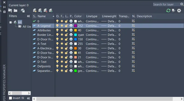
- Block Initially Created Using Draw Command From the Tool Bar
- All the Blocks are created Using Electric Component Layer
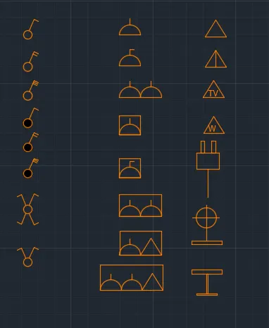
- Each Compomponents is Made into a With Its Respective Name as Shown in Figurre
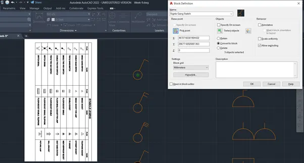
- Go to Insert tab and Click on Create Block Defination Palette or type Block in Command Box
- In the pop Up Box
- Set Name as Single Gang Switch
- Pic Base Point as Center of Circle
- Click on the Select Object Select the Entire Content of the Drawing
- Click on Convert to Block
- Click on Allow to exploding
- Set Block Units to Millimetres
- Click Ok
-
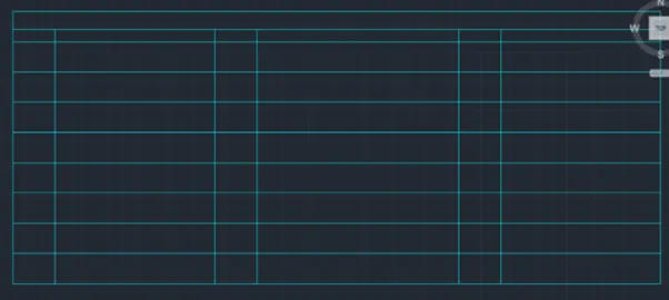
- Create a Rectangle of Size 22000 mm X 9500 Mm
- Explode the Rec using explode Command
- Offset the Top Edge to a Distance of 1000 mm to Bottom
- Offset the Last Ofsted Line to a Distance of 500 to Bottom
- Offset the Last Ofsted Line to a Distance of 1000 to Bottom
- Repeat the Procedure Until Completion
- Give the Command of Divide the top Edge into Three Segments
- Draw Line connection two Lines to the Bottom Edges
- Offset the Lines Drawn to Right to Distance of 1500 mm
- Add All the Blocks into Respective Boxes
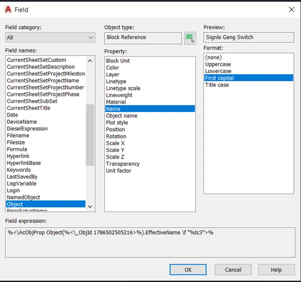
- Go to Insert Tab and Click on Field Box
- Input Pop Up Box go to Object Category
- Click on Select Object and Select the Object Required
- Set Format as First Capital
- Click on Ok and Replace the text in Box next to the Block
-
- Result: -
4.
Aim: - Create the door type for residential building as a block. Save the name of the blocks as type. Use given dimensions or assume dimensions as per industry standards.
Procedure:-
- Select the Layers From the Ribbon Tab Create a New Layers as Per Requirement and Press Enter
- Set the Requirement Layer into Current Layer
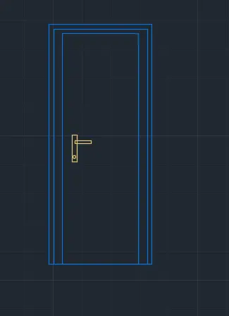
- Draw a Rectangle of Dimensions 2’10” X 6’11”
- Explode the Rectangle Press Enter
- Offset the Lines as per Given Diagram and Press Enter
- Give the Fillet to Use Where its Required and Press Enter
- Draw a Door handle and By Using Rectangle Command Suitable Measurements
- Select the handle Change the Layer into Door Handle Press Enter
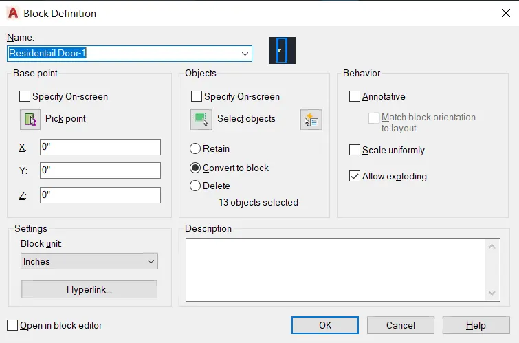
- Give the Command of “B” Press Enter Select the Object and Give the Name as Residential Door-1 and Select the pick up Point as Centre Press enter
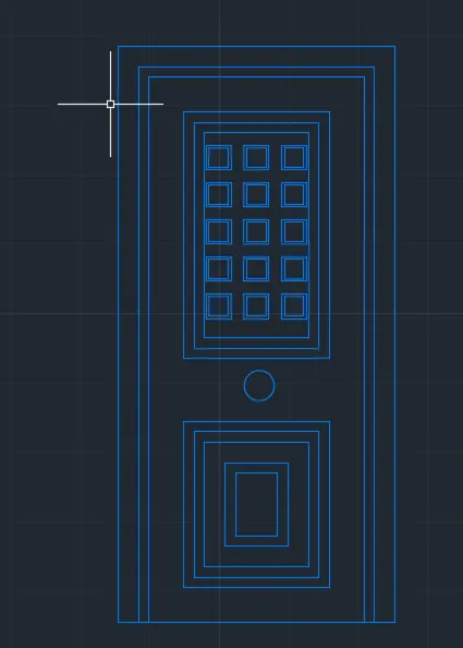
- Draw a Rectangle of Dimensions 3’4” X 6’11”
- Explode the Rectangle Press Enter
- Offset the Lines as per Given Diagram and Press Enter
- Give the Fillet to Use Where its Required and Press Enter
- Draw a Rectangle By Using Rectangle Command Press Enter Place its Inside of the Door and Press Enter
- Select the Object and Give the Command of Array specify the No.of Rows and Columns Press Enter
- Specify the point press Enter
- Draw a Circle as Per Given Figure
- Give the Command of “B” Press Enter Select the Object and Give the Name as Residential Door-2 and Select the pick up Point as Centre Press enter
- Draw a Rectangle of Dimensions 2’9” X 6’11”
- Explode the Rectangle Press Enter
- Offset the Lines as per Given Diagram and Press Enter
- Give the Fillet to Use Where its Required and Press Enter
- Draw a Rectangle as Per Figure
- Draw a Door handle and By Using Rectangle Command Suitable Measurements
- Select the handle Change the Layer into Door Handle Press Enter
- Hatch the Rectangle Press enter
- Give the Command of “B” Press Enter Select the Object and Give the Name as Residential Door-3 and Select the pick up Point as Centre Press enter
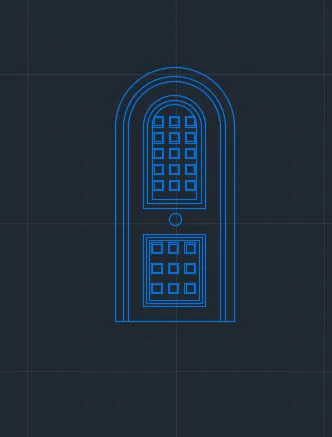
- Create the Door Similar to Door Type 2
- Draw an Rectangular array of Rectangle done in the top Half in the Bottom Half Rectangle too as Shown in Fig.,
- Give the Command of “B” Press Enter Select the Object and Give the Name as Residential Door-5 and Select the pick up Point as Centre Press enter
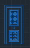
- Create the Door Similar to Door Type 2
- Draw a Circle With Diameter as the Width of the door
- Trim the Circles Bottom Portion
- offsite the Circles Similar to Offset Done for the Rectangle and trim off the Extra Portions as Shown in Figure
- Give the Command of “B” Press Enter Select the Object and Give the Name as Residential Door-6 and Select the pick up Point as Centre Press enter
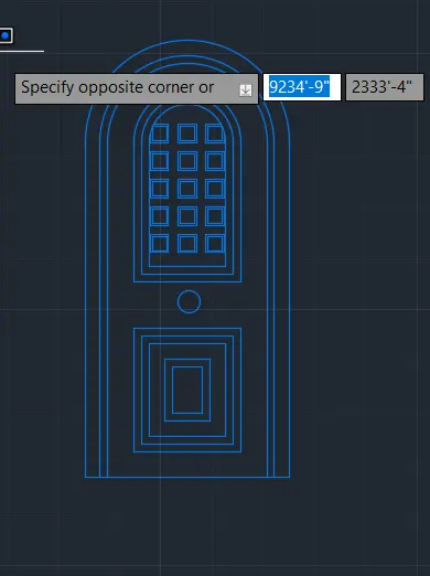
Result: -
Door-1
Door-2
Door-3
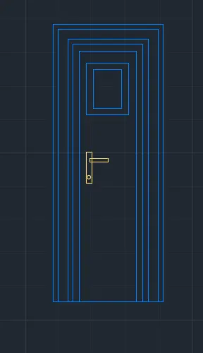
Door-4
Door-5
Door-6
5.
Aim: -Create each shape as a block as shown in the Figure. Save the block and insert them on the table as shown in the Figure.
Procedure:-
- Select the Layers From the Ribbon Tab Create a New Layers as Per Requirement and Press Enter
- Set the Requirement Layer into Current Layer
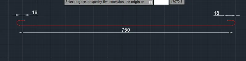
- Give the Command of l and press enter and Specify the Starting point and Give the Length as 750 Cm and Press enter
- Draw a Semi Circle ar Both Ends for the Bend of 18 Cm to up Side
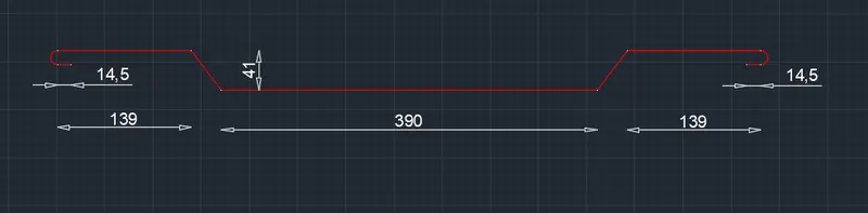
- Give the Command of l and press enter and Specify the Starting point and Give the Length as 730 Cm and Press enter
- Draw a Semi Circle at Both Ends for the Bend of 14.5 Cm to Down Side
- Draw a Line with the Centres Coinciding of Length 390 Cm
- Move the Line Down to a Distance of 41 Cm
- Draw the Inclined Shape of Bar Using line Command as Shown in Fig.,
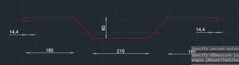
- Give the Command of l and press enter and Specify the Starting point and Give the Length as 712 Cm and Press enter
- Draw a Semi Circle at Both Ends for the Bend of 14.4 Cm to Down Side
- Draw a Line with the Centres Coinciding of Length 210 Cm
- Move the Line Down to a Distance of 80 Cm
- Draw the Inclined Shape of Bar Using line Command as Shown in Fig.,
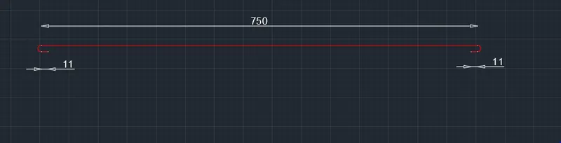
- Give the Command of l and press enter and Specify the Starting point and Give the Length as 750 Cm and Press enter
- Draw a Semi Circle ar Both Ends for the Bend of 11 Cm to Down Side
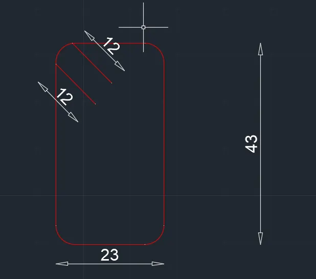
- Draw a Rectangle By Giving the Rec Command in Command Bar press Enter
- Specify the Point Give the Dimensions as 230 mm X 430 mm
- Press Enter
- Give the Command of Fillet to Fillet the Edges with the Radius of 40 mm
- Press Enter
- Draw a Extended Bar by Using Line Command of 12 Cm
- Go to insert tb and Click on define Attribute in Block Defination Palette or Type ATTDEF an Command Box
- In the Popup Box
- Set mode as Lock Position
- Set tag as Type
- Set Prompt as per Requirement
- Place attribute at the any Point on the Screen
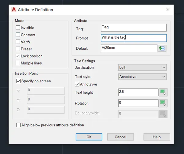
- Go to insert tab and Click ok define Attribute in Block defintaion Palette or type attdef Command Box
- In the Pop up box
- Give the required Data in to it Given Below
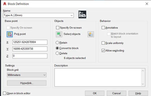
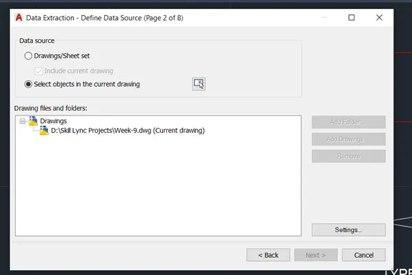
- Go to insert tab and Click on Extract Data in Linking & Extraction tool Bar
- Click ok Create a New Data Extraction and Press next
- Set the Location of Data Extraction
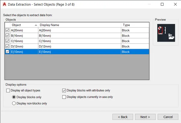
- Click on Select Objects From Current Drawing and Select the Blocks Created and Click
- In the Pop up box
- Give the required Data in to it Given Below
- Select only the data needs to be Extract & Click Next
- Make table Setting and Click Next and Finish
Result.