Creating Bar Bending schedule, Different Door types, and Creation of standard drawing templates using AutoCad
Challenge 9: Creating the bar bending schedule, different door types and creation of standard drawing templates using the AutoCad software.
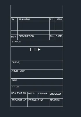
- Creation of templates as shown in figure with the help of title block and text as per industry standards.
Aim- To create a template as shown in the figure.
Procedure:
- Create a new AutoCad file with metric units
- Type the command units and set it to decimal unit and set it to mm
- Type the command dimstyle and set it to the primary units and set the units to the decimal and precision to 0
- Set the limits by using the limits command and specify the end points
- Creating part (a)
- Type the line command L and give the length of 46 mm in –y direction
- Again give the length 23 mm in the +x direction
- Again give the length 46 mm in the +y direction
- Now from the horizontal line give the required no of offsets in +y direction at the required distance
- Now from the vertical line (left boundary) give the offsets in +x direction
- Now use the trim command and trim off the lines unwanted lines
- Use the single line text for typing the information in the rows and columns
- Required geometry is made as shown in the figure.
RESULT:
a)
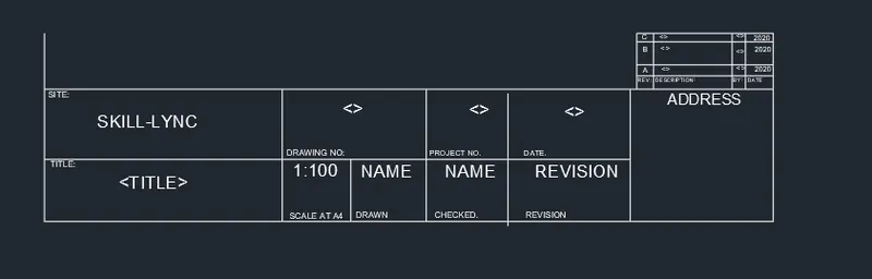
- Creating part (b)
- Type the line command L and specify the point
- Give the length of 24 mm in –y direction
- Give the length of 92 mm in the +x direction
- Give the length of 24 mm in the +y direction
- now from the last horizontal line give the required offsets in +y direction at required distance
- now make the upper right small table using the line command
- give the vertical and horizontal offsets from the boundary of the rectangle
- trim off the required lines using the trim command
- use the single line text of 2mm in height for giving the information and heading in the table
- required geometry is made.
RESULT
(b)
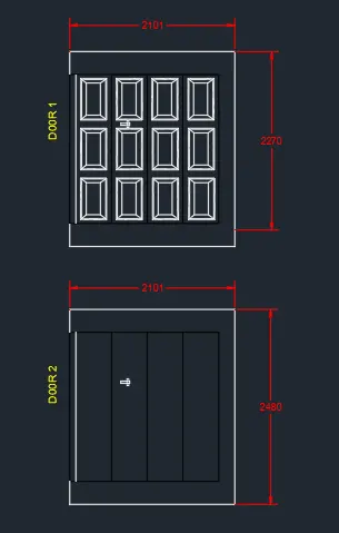
2.Creating the doors type for warehouse as shown in the figure
Aim- To create doors of warehouse using the AutoCad software.
Procedure:
- Create a new AutoCad file with metric units
- Type the command units and set it to decimal unit and set it to mm
- Type the command dimstyle and set it to the primary units and set the units to the decimal and precision to 0
- Set the limits by using the limits command and specify the end points
- Type the rec command and give the length as 2101 mm and width as 2270
- Now from both the horizontal boundary give the offset of 292 mm in the inner side of the rectangle
- Now from the left vertical boundary give the offset of 77mm in the +x direction
- Now from the same vertical boundary give the offset oof 531 mm in the +x direction 3 times
- Trim off the unwanted lines
- Now from making the patterns of doors make the rectangle of required length
- Give the offset at the required distance
- Then join the lines diagonally by keeping the ortho off
- Copy it to all required points keeping the ortho on
- Do the required dimensioning
- Now Erase the patterns of door 1 for getting the door 2
- Required geometry is made as shown in the figure.
RESULT:
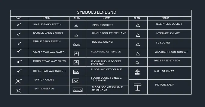
- Creating each symbol as a block with the name in the legend
Aim- To create symbols in the table using AutoCad software.
Procedure:
- Create a new AutoCad file with metric units
- Type the command units and set it to decimal unit and set it to mm
- Type the command dimstyle and set it to the primary units and set the units to the decimal and precision to 0
- Set the limits by using the limits command and specify the end points
- Type the REC command and give the length as 124mm and width as 59mm
- Give the required no of offsets from the horizontal boundary at the required distance
- Give the vertical offset from the vertical boundary at the required distance for getting the columns
- Use the single line text for giving the symbols name headings and subheading of the table
- Make the symbols with the help of REC, LINE, ARC, DONUT and CIRCLE command.
- Required geometry is made.
RESULT:
- Creating the door types for residential building as a block.
Aim- To create doors of residential building as given using AutoCad software.
Procedure:
- Create a new AutoCad file with imperical units
- Type the command units and set it to engineering unit and set it to inches
- Type the command dimstyle and set it to the primary units and set the units to the decimal and precision to 0
- Set the limits by using the limits command and specify the end points
- Creating the doors as shown in the geometry
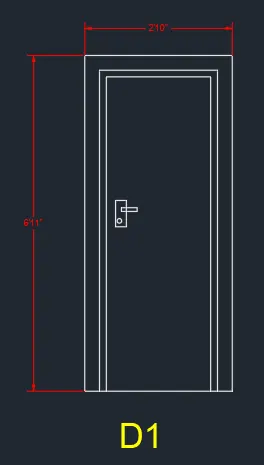
- D1
- Type the REC command and give the length as 2’10” and width as 6’10”
- Use the explode command for exploding the REC.
- Now join the lines except lower horizontal boundary of rectangle using the JOIN command
- Use the offset command and give the offset of joined lines at required distance as shown in the figure
- Make the lock using the rec and circle command
RESULT:Door D1 is made.
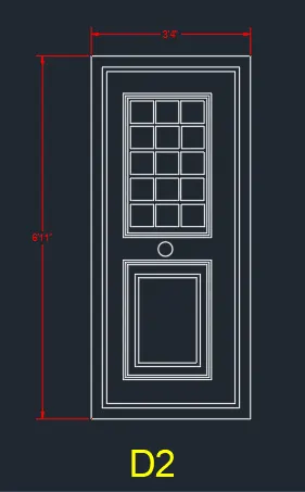
- Creating Door D2
- Type the REC command and give the length as 3’4” and 6’11” respectively
- Give the offset of rectangle at the required distance as shown in the figure
- Now for making the pattern type the REC command
- Make the upper and the lower of required length and shape
- Now from these rectangles give the offset at the required distances as shown in the figure
- Now for block pattern make the square of required length and copy it to required points keeping the ortho on
RESULT: D2 is drawn
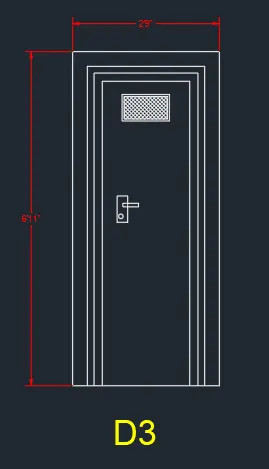
- Creating Door D3
- This door is drawn same as D1.
- Change only length
- Type the hatch command for doing the hatching for getting the mosquito window
RESULT: Door D3 is drawn
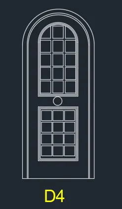
- Creating Door D4
- Type the line command and specify the point
- Give the length of 3160 mm in –y direction
- Give the length of 1704 mm in +x direction
- Give the length of 3160 mm in +y direction
- Join the lines and give the required offsets at required distance
- Select the two corner points of vertical lines and make the curve lines as shown in the figure
- Do the same for getting the inner pattern
- For getting the cone pattern at upper side beside the small square, use the line command by keeping ortho on and make the 2 lines from the curved portion perpendicular to each other
- Make the square using rectangle command of required shape
- Draw the lower portion same as drawn in D2 door
RESULT: Door D4 is made.
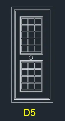
- Creating Door D5
- This door is drawn same as D2
- Delete the lower pattern of inner rectangles
- Make the square using the rectangle command
- Copy the squares using copy command and place it at the required positions keeping the ortho on
RESULT: Door D5 is Drawn
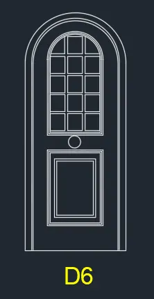
- Creating Door D6
- Draw it exactly same as D4 except the lower pattern
- For lower pattern delete all squares from the lower pattern of D4
- Now type the Rec command and make the rectangle of required length and at required distance
- Give the offset command for getting the inner rectangle
RESULT:Door D6 is drawn
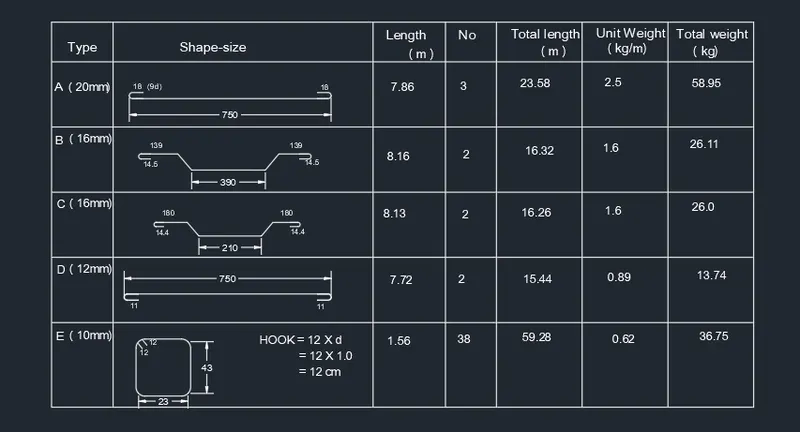
- Creating Bars Bending Schedule and each shape as a block
Aim- To create Bar Bending schedule of residential building as given using AutoCad software.
Procedure:
- Create a new AutoCad file with imperical units
- Type the command units and set it to engineering unit and set it to inches
- Type the command dimstyle and set it to the primary units and set the units to the decimal and precision to 0
- Set the limits by using the limits command and specify the end points
- Make the type of bars like type A,B,C and D with help of line command, arc option
- Use start end direction option from the arc to get the semicircle like shape of bar
- Do the required dimensioning as shown in the table
- For making type E use the rectangle command and fillet command to get the curved corners.
- Make the hooks with the help of the line command
- Do the required dimensioning
- Now for making the table type the Rec command and give the length of 400 mm and width of 250 mm of required size as shown in the figure
- Now from the upper horizontal boundary give the required offsets in –y direction
- Now from the left vertical boundary give the required offsets in +x direction.
- Use the single line text for detailing and giving the heading in the table
RESULT: Bar Bending schedule is Drawn