Creating Bar Bending schedule, Different Door types, and Creation of standard drawing templates using AutoCad
AIM: To create the templates as shown in Figures.
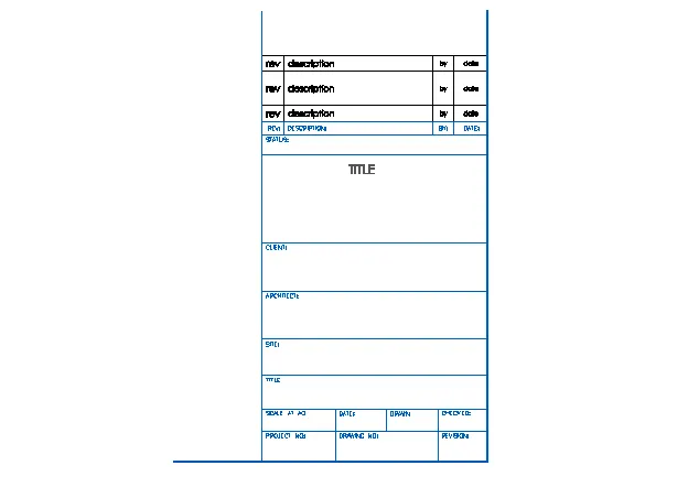
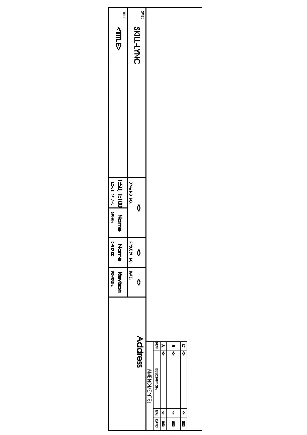
INTRODUCTION: AUTOCAD software is used to design and drafting of 2D & 3D structures in construction field, it is also used to draw plans.
Procedure:
1. Autocad software is opened and then new file is created.
2. From layer opiton a layer is created and a colour is speciifed and a name is given as table.
3. Now table is created from the options or directly a table is created using L line command.
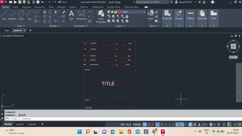
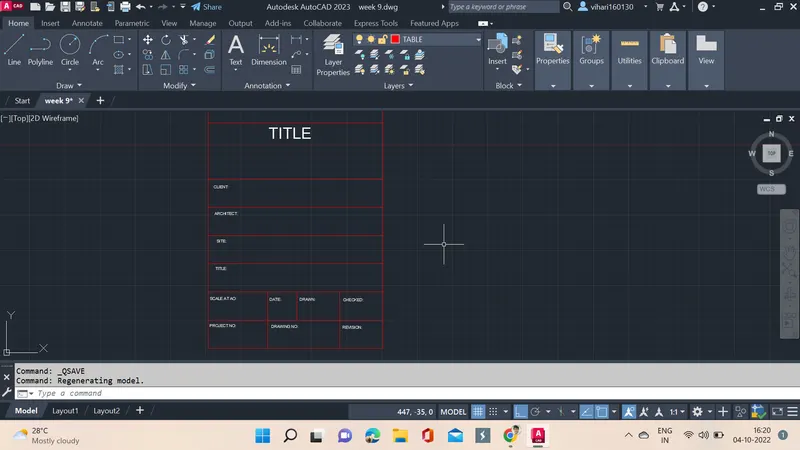
4. Another table is created and MTEXT is used to complete the next table as given in the figure.
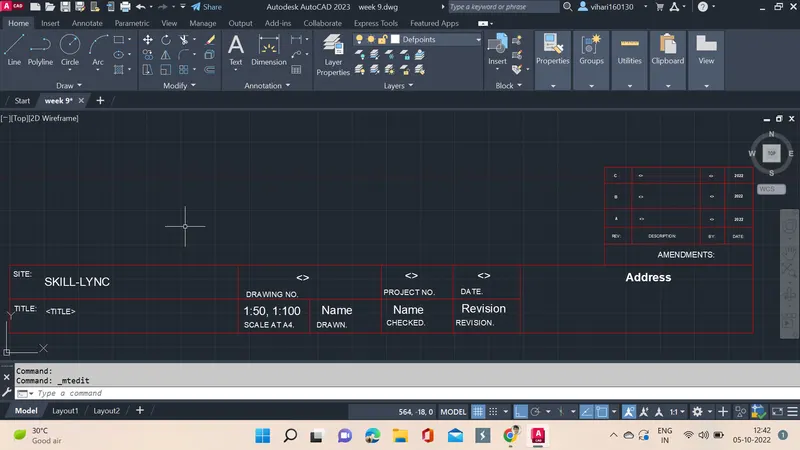
RESULT: Using autocad the templates are created according to the given figure.
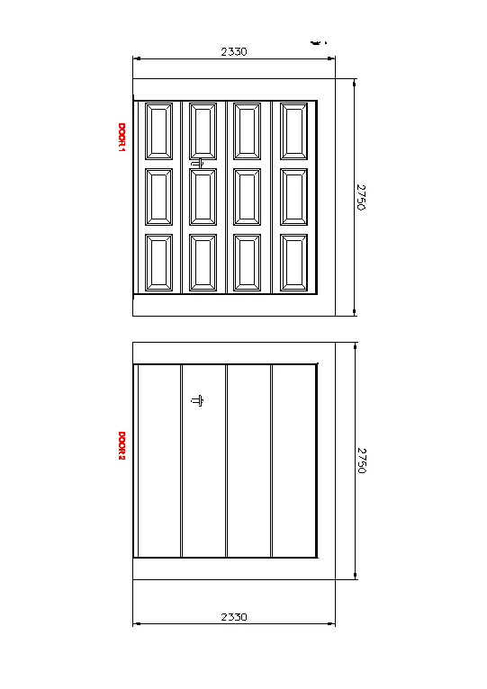
AIM: To create the doors type for warehouse as shown in the Figure.
INTRODUCTION: AUTOCAD software is used to design and drafting of 2D & 3D structures in construction field, it is also used to draw plans.
PROCEDURE:
1. Autocad software is opened and then new file is created.
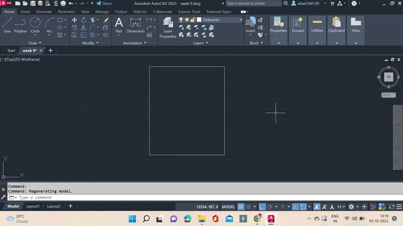
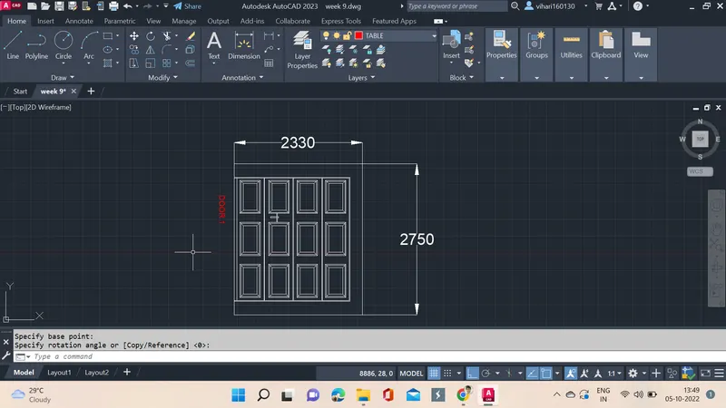
2. REC command is used then dimensions d is entered, then length is specified as 2330, breadth is specified as 2750.
3. A rectangle with the above dimensions is drawn.
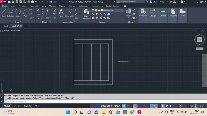
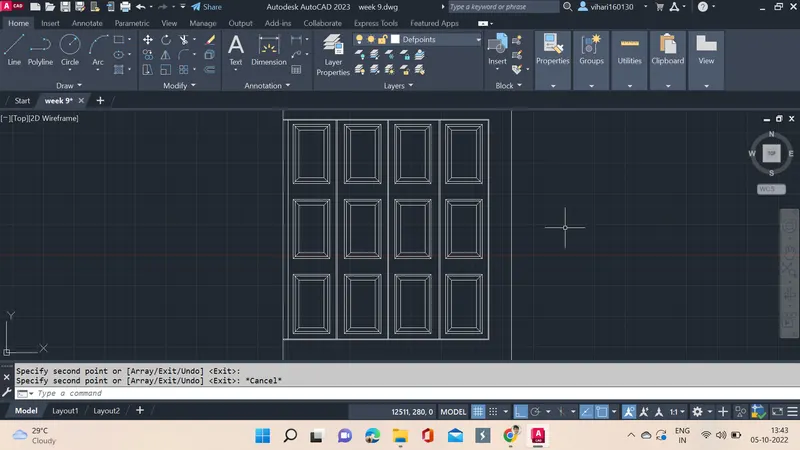
4. in the next step it is divided into four parts before that a line is drawn from right corner @-230,0 and a line is drawn @0,2250.
5. then it is closed, O offset command is used to draw three lines dividing the door frame into 4 parts. as shown
6. next step is to draw panels and complete door 1.
7. A nob is to be made and then door 1 is completed, DIMLIN is used and dimensions are specified.
8. second door is also almost the same so it can be copied using CO command.
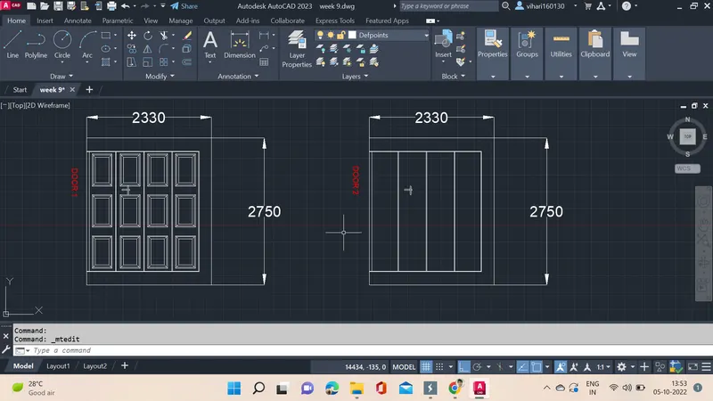
RESULT: Using autocad doors are created according to the given figure.
AIM: To create each symbol as a block with the name given in the legend. After creating the blocks arrange them in the legend as shown in the Figure.
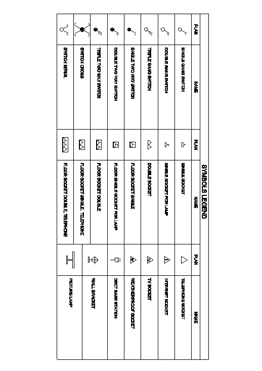
INTRODUCTION: AUTOCAD software is used to design and drafting of 2D & 3D structures in construction field, it is also used to draw plans.
PROCEDURE:
1. Autocad software is opened and then new file is created.
2. From layer opiton a layer is created and a colour is speciifed and a name is given as table.
3. Now table is created from the options or directly a table is created using L line command.
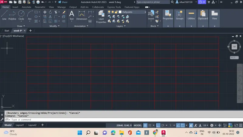
4. MTEXT command is used and text is written as per the figure.
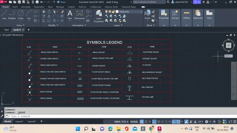
RESULT: Blocks are created using autocad for the electrical units.
AIM: To create the door type for residential building as a block.
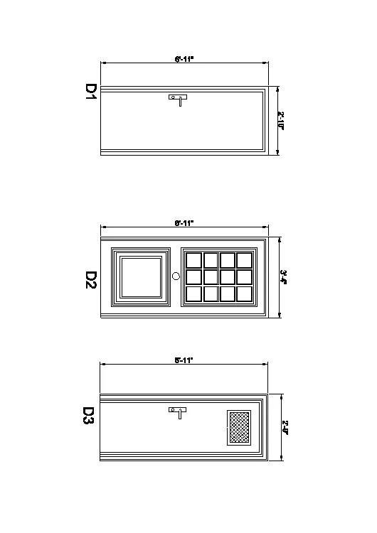
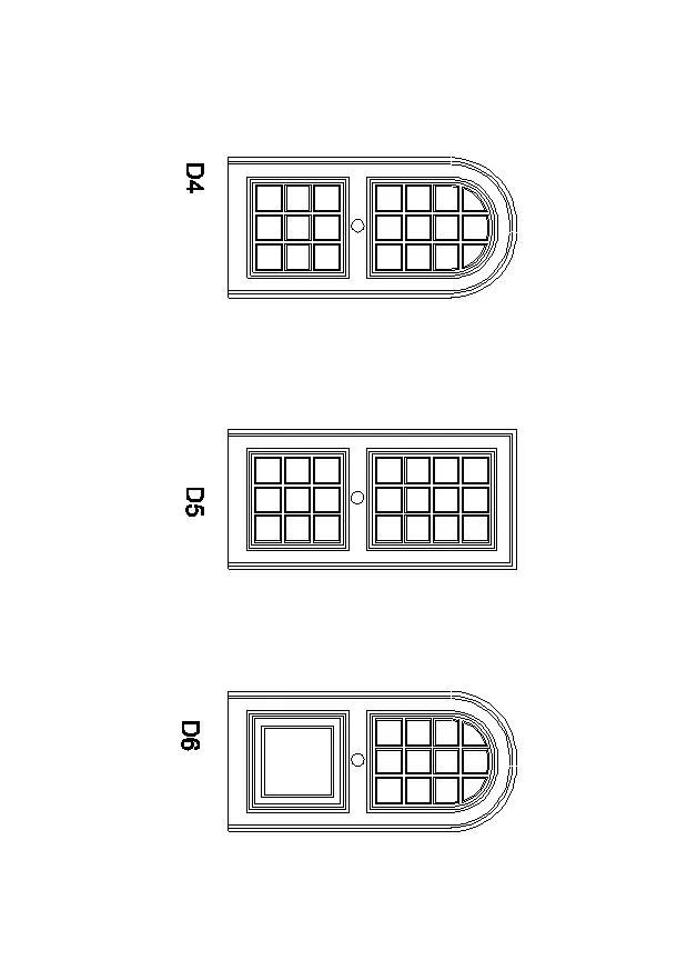
INTRODUCTION: AUTOCAD software is used to design and drafting of 2D & 3D structures in construction field, it is also used to draw plans.
PROCEDURE:
1. Autocad software is opened and then new file is created.
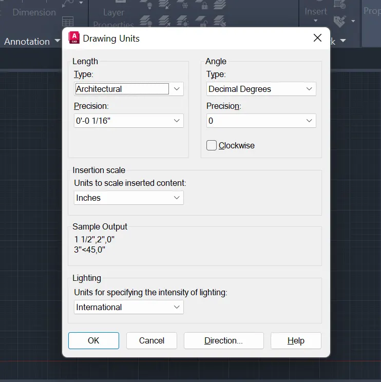
2. Units command is used then units are changed to architectural.
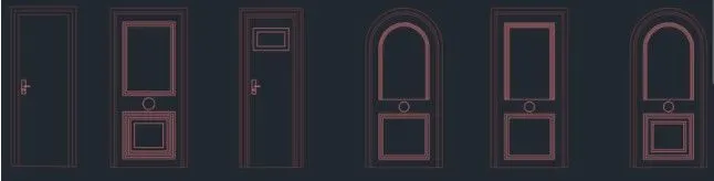
3. Line command is used and the doors are drawn according to the dimensions.
4. Fillet command is used to draw the curves at the corners for few doors.

5. Layer option is selected and a layer is created, a name is specifed as door frames and colour is defined to identify easily.
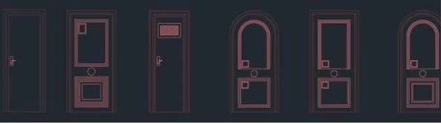
6. Layer option is selected and a layer is created, a name is specifed as door panels and colour is defined to identify easily.
7. Door handle is created for door 1 which is copied for the 3rd door.
8. for the rest doors rectangles are made for one door and it is copied for other doors.
9. REC command and O command is used to draw the door panels.
10. for door 3 H hatch command is used and hatching is done.
11. DIMSTY is used and dimensions are changed to architectural.
12. DIMLIN is used to specify the dimensions.
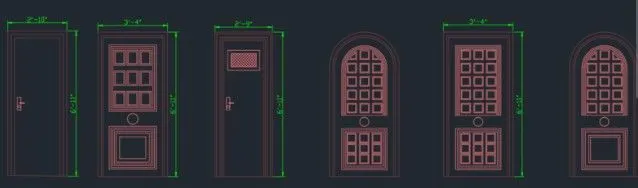
RESULT: Doors are created using autocad as per the given figures.
AIM: To create each shape as a block as shown in the Figure.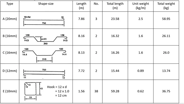
INTRODUCTION: AUTOCAD software is used to design and drafting of 2D & 3D structures in construction field, it is also used to draw plans.
PROCEDURE:
1. Autocad software is opened and then new file is created.
2. From layer opiton a layer is created and a colour is speciifed and a name is given as table.
3. Now table is created from the options or directly a table is created using L line command.
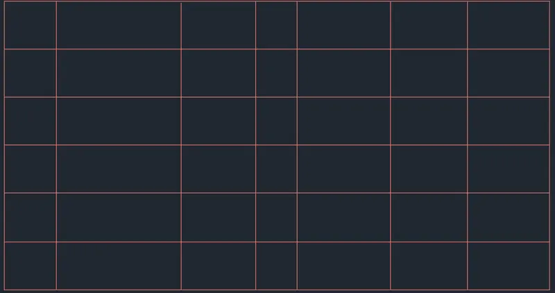
4. Now a layer is created and a name is specifed as bars, and colour is defined.

5. Now a layer is created and a name is specifed as name, and colour is defined.
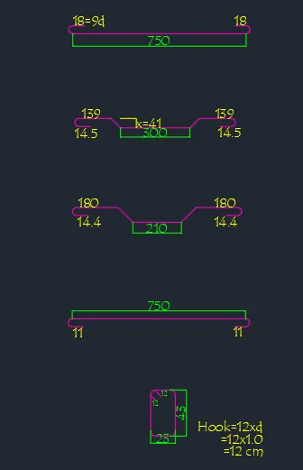
6. MULTILINE is used and textis written in the drawn table as per the given figure.
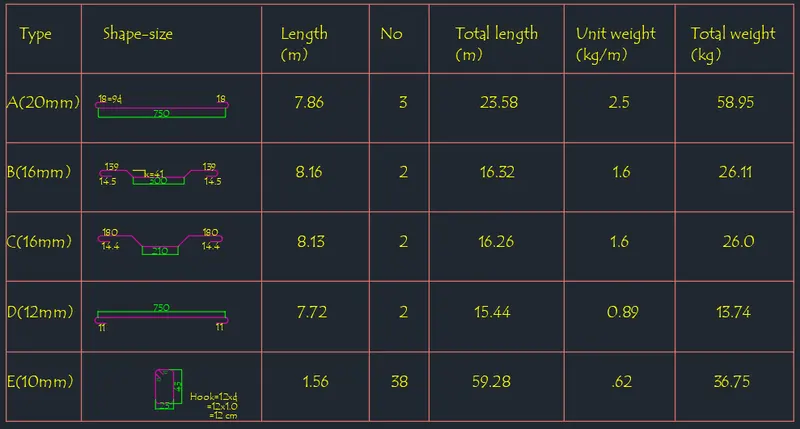
RESULT: Table is created and text is written using autocad for the given figure.