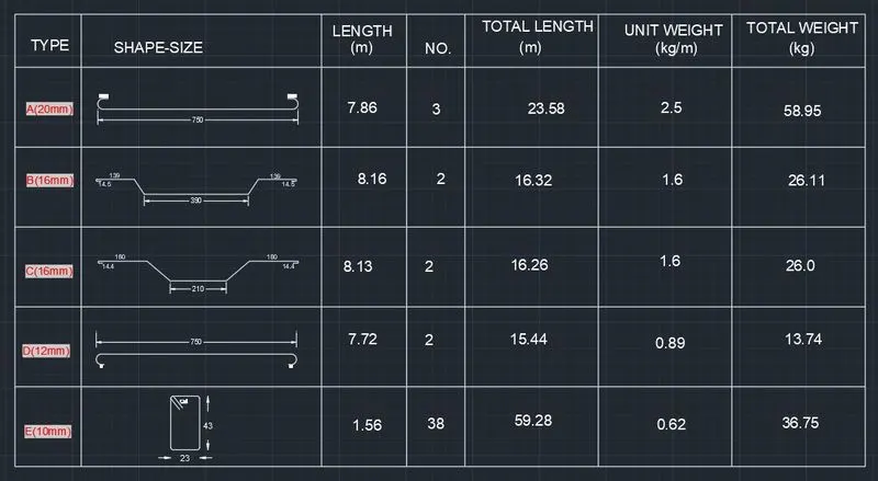
Creating Bar Bending schedule, Different Door types, and Creation of standard drawing templates using AutoCad
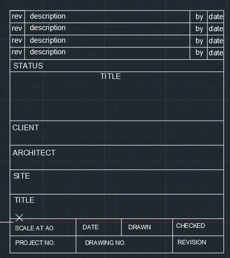
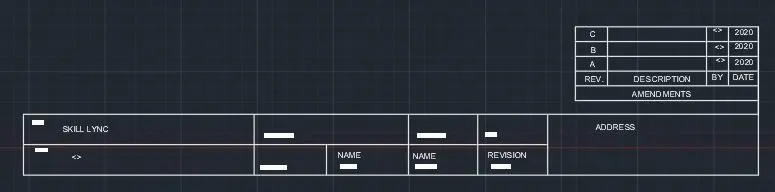
1) Aim :- To create the templates as shown in the question and name them separately as a block
procedure :-
- take a new autocad drawing and take the un9t as mm
- first we have to make the title block1. for that draw a vertical and horizontal line. offset the horizontal line 5 times at a height of 5mm .
- the next row offset by 20mm and the remaining 5 rows about 10mm. offset the vertical line apppropriately and then use trim command to trim off the unwanted lines.
- select text command and write down the require texts as per the question.
- select the entire drawing and select block command. enter the name of the block as 'custom1_titleblock', pick point at the bottom left corner and press ok.
- sismilarly using the line , offset and trim command make the seconf title box . make it into a block and name it as 'custom2-titlebox'.
- the resulting boxes are as shoen below
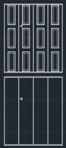
2) AIM:- To create the doors type for warehouse as shown in the Figure and to make them into a block.
procedure :-
- select a new cad drawing and of unit in mm .
- draw a rectangle of size 2330mm x2750mm using line tool and keeping ortho mod eon
- offset all the sides with 2mm length.
- measure distance of the horizontal line and divide it into 4 . using that value offset the vertical line3 times. offset each vertical line by 1mm to either side and delete the middle line, to get panelled doors.
- to make the door handle , draw a small reactangle with the longer dimension in the vertical direction. draw another slightly bigger rectangle perpendicular to the first one. fillet the second rectangles edges. make this into a block and name it door handle .
- this will give us door 2
- now copy this door and place it above door 2 in order to draw door 1 as per the question.
- measure the vertical distance using distance option and divide it into 3 by offseting horizontal lines. offset each horizontal line 2mm to the top and bottom and delete the central line. this will give us the positions of the smaller door panels .
- measure the horizontal and vertical distance of the top left rectangle that we have drawn. using these dimensions draw a recatngle outside the drawing , usisng rectangle tool, with vertical dimension same and taking half the horizontal dimension.
- offset this rectangle by 1mm using offset tool. offset the inner rectangle by 2.5mm .now join the corners of the inner and middle rectangle using line option.
- select this entire drawing and make it into a block. pick point as the centre of the top horizontal line and name it door panel.
- now insert this blockin the 3 panels vertically and to the centre . copy the 3 panels and paste them in the other 4 panels by taking mid point as the pick point.
- the resulting figure is as shown below.
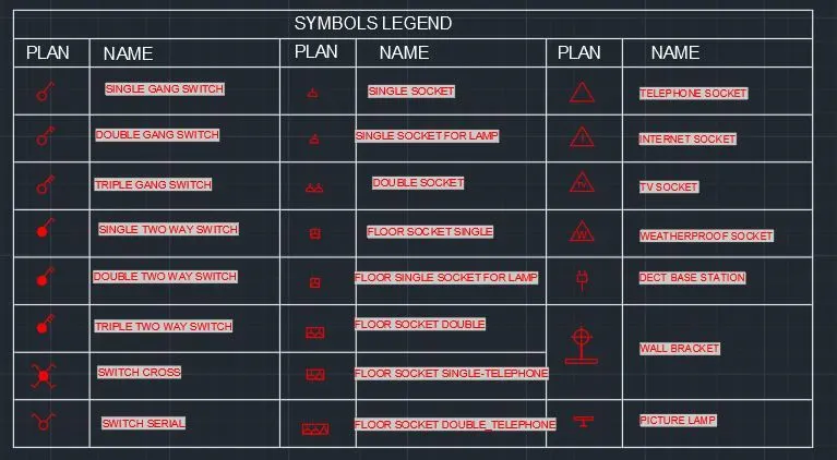
3) AIM:- To ceate a legend as shown in the question.
procedure:-
- take a new autocad drawing with unit as mm
- first draw a table with 6 columns and 10 rows using line command and offset command
- draw the first symbol and make it into a block. name the block as the symbols name , for eg. single gang switch.
- now place the symbol in the first column of the table and in order to insert the name go to insert option.
- go to field option. select objects in field category and select the object by clicking on the symbol next to object type.
- select 'name', from property option.place the name in the column next to the symbol.
- repeat the same for all the symbols shown in the question
- the resultung table is as shown below
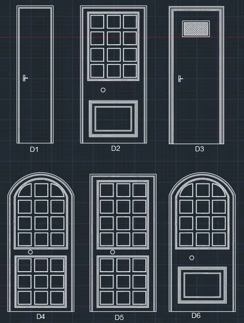
4) AIM:- To create the door type for residential building as a block.
procedure:-
- select new drawing with unit as inches.
- to draw D1, draw a rectangle of given dimensions using line option and ortho mode on, and then offset the 3 sides of the recatngle. draw the handle of the door using rectangles. and save them a sa block.
- draw D2 with the given dimensions. the detailings on the door can be drawn using rectangle option and by copying the small squares to mak ethe required pattern. draw a circle which represents the door knob.
- D3 is simpler . the door is to be drawn using line option according to given dimensions. then draw another small rectangle to be placed on the top of the door. now hatch inside the recatngle and insert the door knob that was made into a block.
- next draw D5. the same dimensions of D2 can be taken . copy D2 down and delete the bottom rectangle. copy the top array of rectamgles and delete the top row of small squares and adjust the boundaries . select the array of squares and place it at the bottom of the door.
- copy D5 to draw D4. draw a line in the horizontal direction at the level of the bottom of the first row of small squares and trim off the lines of the boundary above the line.delete the two adjacent sides of the squares at the 2 sides and make an arc using arc option.
- make an arc starting from lines that have been trimmed off. this gibes us D4.
- copy D4 to the side of D5 and delete the bottom array of squares. copy and paste the bottom of D2 and place it in the bottom of D6.
- now select eac door seperately an dmak ethem into blocks and name them D1,D2,D3,D4,D5 and D6.
- the resulting drawing is as given below.
5) AIM:- To create each shape as a block as shown in the question.
procedure :-
- select new cad drawing with unit as mm.
- draw a table using lines and offset option with 7 columns and 6 rows.
- the first figure is drawn using line option. use fillet to curve the ends of the reinforcement drawing .
- dimension it using dimension tool and wrote texts using text tool.
- select the drawing and make it into a block. while naming th eblock make sure to name it according to th enam erequired in the table.
- similiarly complete the rest of the drawing using line and fillet tool. dimension it using dimension tool .
- place each drawing in the table as required and fill in the details of the table using text option according to the question.
- to get the type of drawing, go to insert option.go to field option. select objects in field category and select the object by clicking on the symbol next to object type.select 'name', from property option.place the name in the column next to the symbol.
- repeat the same for all the drawings shown in the question
- the results of the drawing are as shown in the figure below.