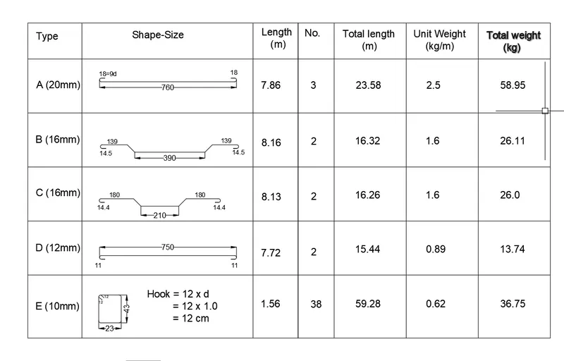
Creating Bar Bending schedule, Different Door types, and Creation of standard drawing templates using AutoCad
1.AIM
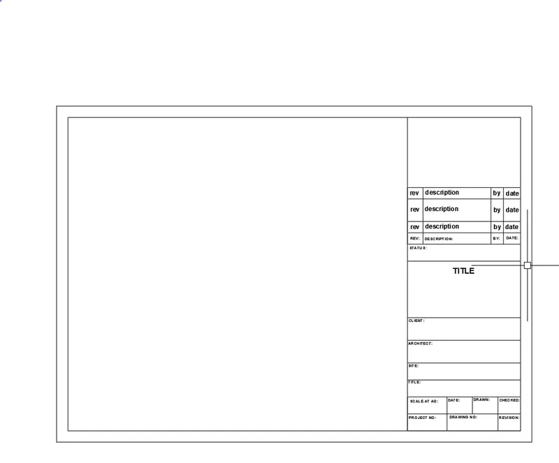
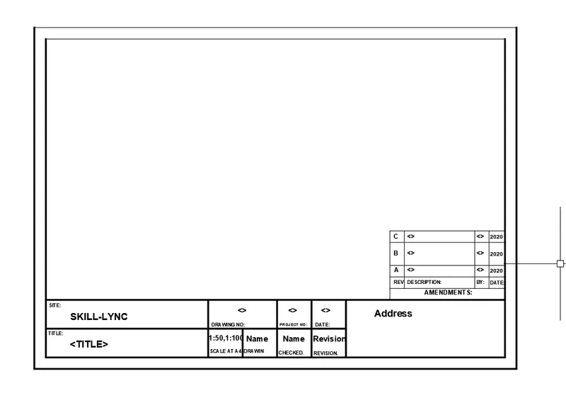
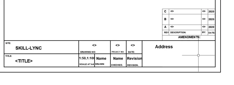
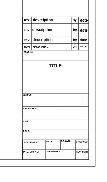
To draw the Templates of title block as per industry standars using the various commands in Auto CAD.
INTRODUCTION
- The title block of the drawing is usually located on the bottom or lower right hand corner.
- It contains all the information necessary to identify the drawing and to verify its validity.
- The drawing title and the drawing number are used for identification and filling purposes.
PROCEDURE
- To create a new drawing sheet .
- Type ,,UN’ to set the units of current format of measure.( MILLIMETERS).
- Type ,,LIMITS’ to set the maximum dimension limits on the particular page.
- Then, to set the required sheet size of 594mm x 841mm.
- After that to create the title block of the diagram on sheet at right side or bottom of the sheet.
- Type ,,L’ - Line commands allows to creating a line where the end points allows creating a line where the end points are dimensional co-ordinates.
- TYPE ,, XLINE’ to draw the infinity length of line, can be draw it free or set it to be Horizontal or Vertical, follow a certain angle.
- Type ,, OFF’ – offset command to create a new object that specified distance from an existing objects or through a specified points.
- Type ,, Tr’ – Trim command is used to trims off an objects cutting the extra edges on objects.
- Type ,, Text’ to create the text ( SINGLE or MULTI ), select and change the properties of standard size.
- If we create the text, therefore changed the text height by select the object, right click and then to go properties , then to change it.
- COPY – this commands is used to selected objects from a given square to destination, learning a copy at the originally selected location.
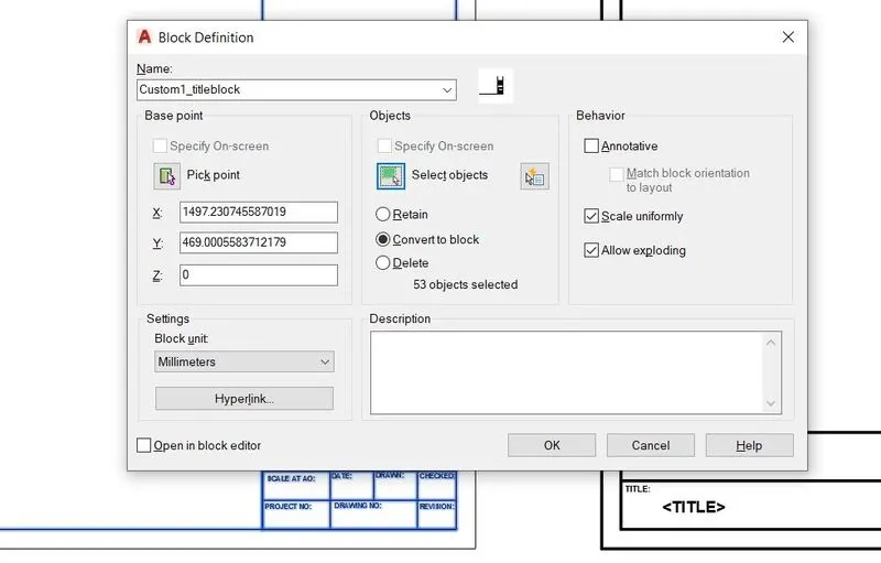
- Command ..BLOCK’ to save the objects.
- After saved it, to Command .. INSERT’ to plot the same diagram forever at the drawing file. This is used to save the accessories in the house for easily plot the diagram.
- If we given different name for easily identify the objects.
- Finally, to save the diagram .
RESULTS
The diagram of the TITLE Block is drawn as per dimensions using the software of Auto CAD.
DIAGRAM
2.AIM
To create a Door type of Warehouse using the various commands in Auto CAD.
INTRODUCTION
- A warehouse is a building for storing goods.
- Warehouse are multifarious spaces that may require special purpose doors to suit certain needs, the main purpose to get a better safety of goods.
PROCEDURE
- To create a new drawing sheet .
- Type ,,UN’ to set the units of current format of measure.( MILLIMETERS).
- Type ,,LIMITS’ to set the maximum dimension limits on the particular page.
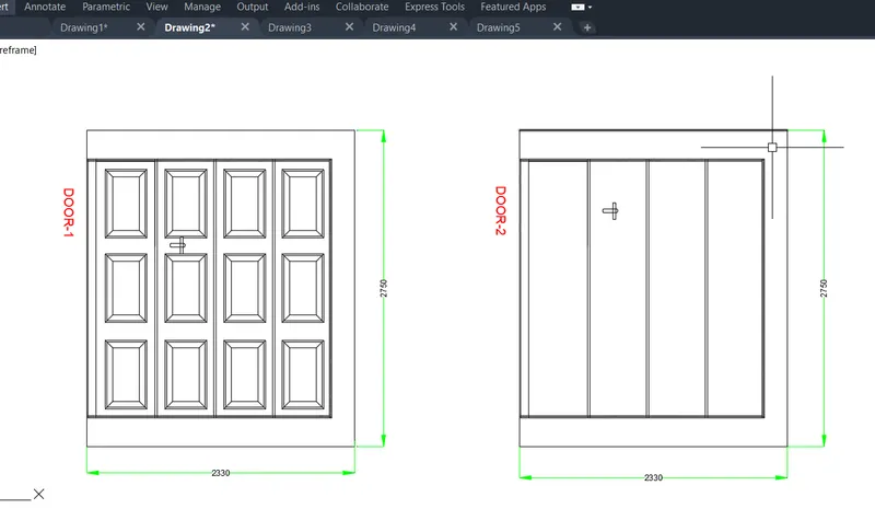
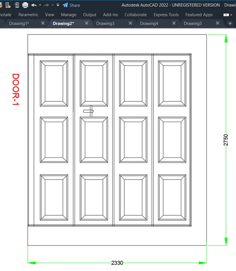
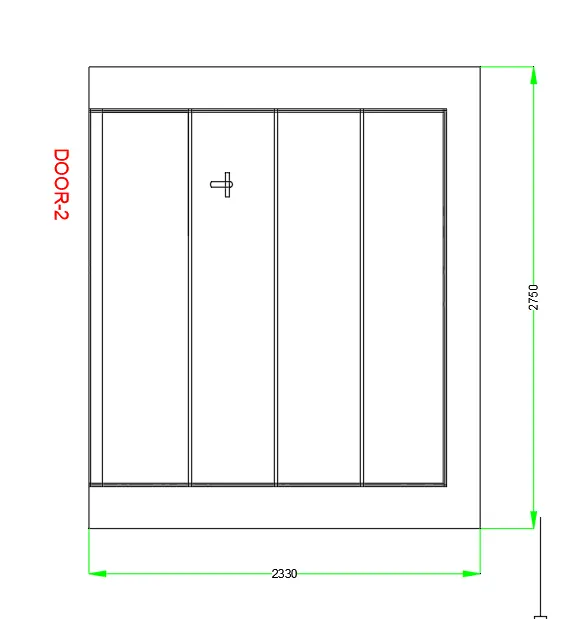
- The Dimension of door is 2330mm x 2750mm.
- Type ,,L’ - Line commands allows to creating a line where the end points allows creating a line where the end points are dimensional co-ordinates.
- TYPE ,, XLINE’ to draw the infinity length of line, can be draw it free or set it to be Horizontal or Vertical, follow a certain angle.
- First to create the outer line of the door, then to immerse the inner part of the elevation.
- Command ..REC’ to create the rectangle of the given elevation.
- Type ,, OFF’ – offset command to create a new object that specified distance from an existing objects or through a specified points.
- We assume the standard dimension of the door at any other area.
- Type ,, Tr’ – Trim command is used to trims off an objects cutting the extra edges on objects.
- COPY – this commands is used to selected objects from a given square to destination, learning a copy at the originally selected location.
- Type ,, Text’ to create the text ( SINGLE or MULTI ), select and change the properties of standard size.
- The text color is selected the layer properties of RED.
- TYPE ,,DLI’ in command bar to give the dimension of the plan.
- TYPE ,,D’ in command bar to give the size of the dimension and size of the arrows, changing tool command is DDIM.
- Finally, to save the diagram .
RESULTS
The diagram of the DOOR TYPE OF WAREHOUSE is drawn as per dimensions using the software of Auto CAD.
DIAGRAM
3.AIM
To create a Symbol as a block using the various commands in Auto CAD.
PROCEDURE
- To create a new drawing sheet .
- Type ,,UN’ to set the units of current format of measure.( MILLIMETERS).
- Type ,,LIMITS’ to set the maximum dimension limits on the particular page.
- Type ,,L’ - Line commands allows to creating a line where the end points allows creating a line where the end points are dimensional co-ordinates
- TO create a table by using table command or line command for the given requiremet.
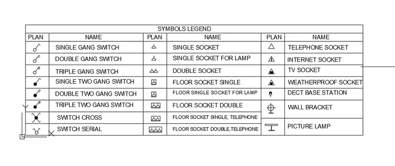
- After create the symbol, then to create the given symbol of electrical appliances, by using the proper requirement commands.
- After that the creation of symbol, follow to save the objects in Block.
- Type,, BLOCK’ T open the block palletes, then take the pick point and objects to saved it .
- Given the proper understanding name of the objects, because of directly we taken the objects, the name also arrived at required place.
- Type,, INSERT’ to insert the saved objects from the block to the drawing sheet.
- Finally, to save the diagram .
RESULTS
The diagram of the TABLE of Symbol is drawn as per dimensions using the software of Auto CAD.
DIAGRAM
4.AIM
To create a DOOR type of the residential buildings using the various commands in Auto CAD.
INTRODUCTION
- A door is used to connect the areas wherever we given open of the entry of any area of the buildings.
- A door is made up of major Of Wood at a residential purpose.
- It needs to better aesthetic view of the entrance.
- The doors are classified depends upon the various place of residential home like, bathrooms, bedroom, pooja room.., etC..
PROCEDURE
- To create a new drawing sheet .
- Type ,,UN’ to set the units of current format of measure.( feet and inches).
- Type ,,LIMITS’ to set the maximum dimension limits on the particular page.
- Type ,,L’ - Line commands allows to creating a line where the end points allows creating a line where the end points are dimensional co-ordinates
- To create the outer dimension of the door as per indian standard.
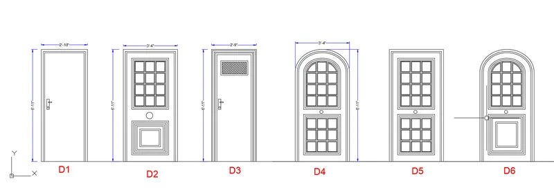
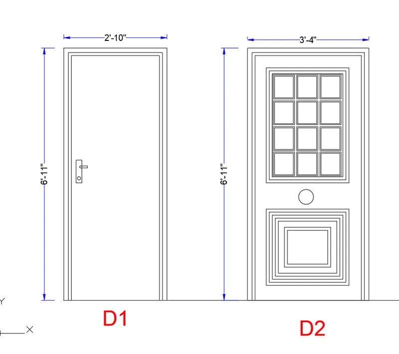
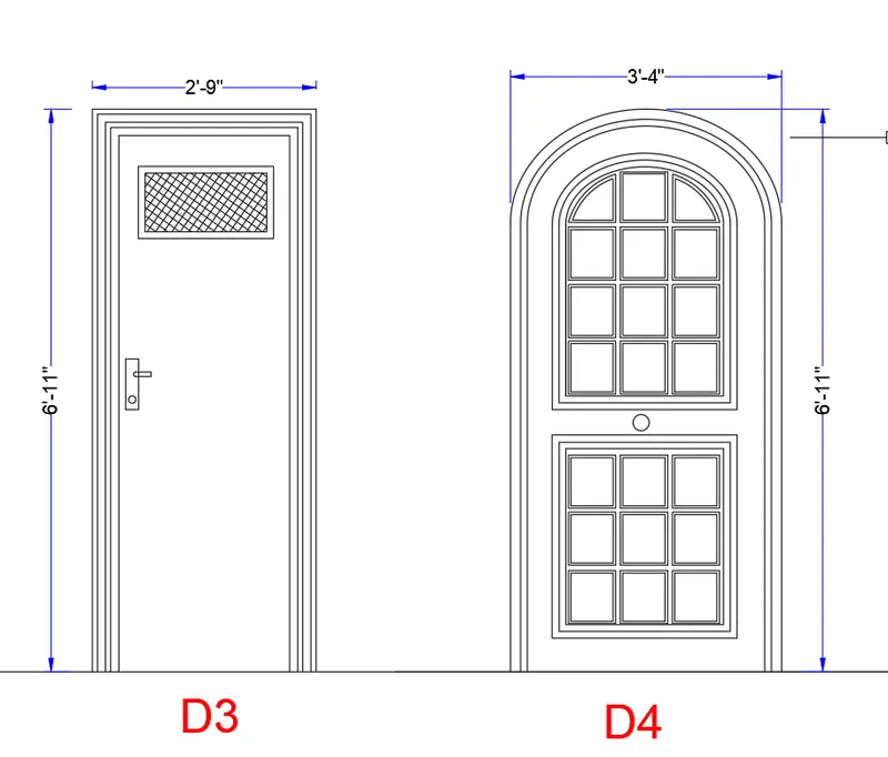
- The dimension of the door is 2’0” x 6’11” , 3’4” x 6’11” and 2’9” x 6’11”.
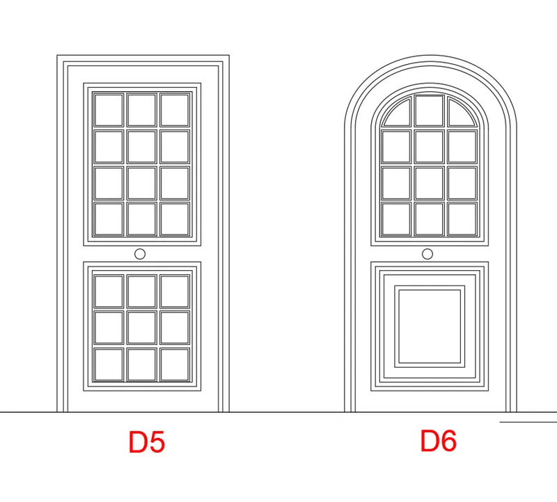
- The doors are classified into D1, D2, D3, D4, D5 and D6.
- The elevation of door at D1, D2, D3 and D5 is a rectangular in shape and D4, D6 is the top Dome shape.
- And wherever we required for not given the dimensions, then to assume the regular size of standard.
- First to create the outer line of the door, then to immerse the inner part of the elevation.
- Command ..REC’ to create the rectangle of the given elevation.
- Type ,, OFF’ – offset command to create a new object that specified distance from an existing objects or through a specified points.
- Type ,, Tr’ – Trim command is used to trims off an objects cutting the extra edges on objects.
- COPY – this commands is used to selected objects from a given square to destination, learning a copy at the originally selected location.
- Type ,, Text’ to create the text ( SINGLE or MULTI ), select and change the properties of standard size.
- The text color is selected the layer properties of RED.
- Type,, BLOCK’ T open the block palletes, then take the pick point and objects to saved it .
- To saved the all types of the DOORS and then we Insert easily to wherever reuired.
- Given the proper understanding name of the objects, because of directly we taken the objects, the name also arrived at required place.
- Type,, INSERT’ to insert the saved objects from the block to the drawing sheet.
- Finally, to save the diagram.
RESULTS
The diagram of the Door type of Residential buildings is drawn as per dimensions using the software of Auto CAD.
DIAGRAM
5.AIM
To create a Table with a content using the various commands in Auto CAD.
PROCEDURE
- To create a new drawing sheet .
- Type ,,UN’ to set the units of current format of measure.( MILLIMETERS).
- Type ,,LIMITS’ to set the maximum dimension limits on the particular page.
- Type ,,L’ - Line commands allows to creating a line where the end points allows creating a line where the end points are dimensional co-ordinates
- TO create a table by using table command or line command for the given requiremet.
- TO create a table by using table command or line command for the given requiremet.
- After create the symbol, then to create the given symbol of electrical appliances, by using the proper requirement commands.
- After that the creation of symbol, follow to save the objects in Block.
- Type,, BLOCK’ T open the block palletes, then take the pick point and objects to saved it .
- Given the proper understanding name of the objects, because of directly we taken the objects, the name also arrived at required place.
- Type,, INSERT’ to insert the saved objects from the block to the drawing sheet.
- Finally, to save the diagram .
RESULTS
The diagram of the Table is drawn as per dimensions using the software of Auto CAD.
DIAGRAM