Creating Bar Bending schedule, Different Door types, and Creation of standard drawing templates using AutoCad
AIM: Sketch the below mentioned drawing as per instructions given in "a"to "e".
(a). Create the templates as shown in Figures. Take the size of the title block as per industry standards or you can assume it as per the size of the paper. Use text and attributes wherever required. After creating the title block you need to save it as a block with names: Custom1_titleblock and Custom2_titleblock, respectively.
(b). Create the doors type for warehouse as shown in the Figure. You need to create each door type as per standard size or given dimensions. Create the blocks of this door type after creating them.
(c). Create each symbol as a block with the name given in the legend. After creating the blocks arrange them in the legend as shown in the Figure.
(d). Create the door type for residential building as a block. Save the name of the blocks as type. Use given dimensions or assume dimensions as per industry standards.
(e). Create each shape as a block as shown in the Figure. Save the block and insert them on the table as shown in the Figure.
INTRODUCTION:
- Here Drawings are given in two dimensions i.e., mm & feet/inches so it is required to define the units before sketching with required precision of that sketch.
- Drawing of same type should be sketched in a separate DWG form for replacing the scaling error further.
- Define the origin of any sketch using UCS command.
- I have assumed some dimensions arbitrarily on intuition basis.
- I have attached the result of the drawing in the jpg form by taking the screenshots.
Procedure:
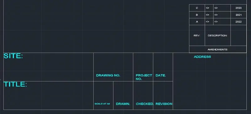
1. I have chosen two options to sketch the above drawing.
- Lower rectangular block (297 * 70 mm) is drawn using line command with text command given in the HOME tab.
- Right hand side cell "address" is of dimensions (90*70 mm) while left one is of (110 * 70mm) with bifurcation at the middle.
- Middle four cells are of (24 * 35 mm) unit, divided using Div command to make four equal segments of 24 mm each.
- For texting using Text command, it’s better to use copy option with base point mentioned at the respective node of each cell in order to eliminate the alignment error.
- Upper Rectangular block (70*60 mm) is drawn using Table command in the "annotate" option in the HOME tab.
- Define the table properties like General, TEXT, Borders etc. to set better into the print layout.
- After drawing the above sketch with mentioned label data attached above, use define attribute "ATTDEF" command to fill the spaces.
- Fill the Tag, prompt, default option given in the ATTDEF window followed by creating the block using "B" command.'
- Select the whole table as a object while selecting the object for a block.
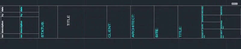
1. Here the table is drawn using line command with dimensions of 35* 297 mm.
- there are 12 cells in a vertical line with 6 are of 15 units, 5 are of 25 units while title cell is of 52 unit comprising overall 297 units.
- here we have chosen DDTEXT command to write the default text with repeating use of copy command having base point as corresponding node of the particular cells.
- Following the 3rd point helps in aligning the text in the same order over the complete table.
- After drawing the table with labelling, its mandatory to define the attributes over the complete table using the Insert option for define the location.
- After defining the Whole table with attribute, it’s required to create the block of the table along with attribute data.
- We may use "ATTEDIT" command in the future to edit the palette without doing repetitive task.
FIGURE(B):
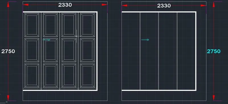
1. WE have defined the dimensions on intuition basis as follows:
Outer margin of the doors are of 300 mm with hatching thickness of 25 mm over three sides of the above attached door.
Door consist of 4 columns of 2100mm with three panels divided equally.
10 mm gap is provided between two nearby column (500*4 + 3*10) mm.
Rec & offset command is used by dividing sections equally in both Axis.
- As the drawing has a symmetry so it’s better to use the copy command.
- After sketching the drawing, create the block by selecting the complete door while object selection.
- Before creating the block, use DIMLINEAR command to label the door preceded by setting the ANNOTATE option in the HOME tab.
FIGURE(C):
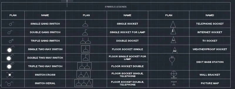
1. Firstly, draw the "plan drawing" using the line, arc (start, centre, length), rec etc. command.
- After Drawing every cell, create a block with name as mentioned in the nearby cell of the table.
- After Defining the all blocks with names mentioned in the above table, Draw the table using the line command.
- Here nearly all the legends drawing are sketched with a dimension of 200*200 mm.
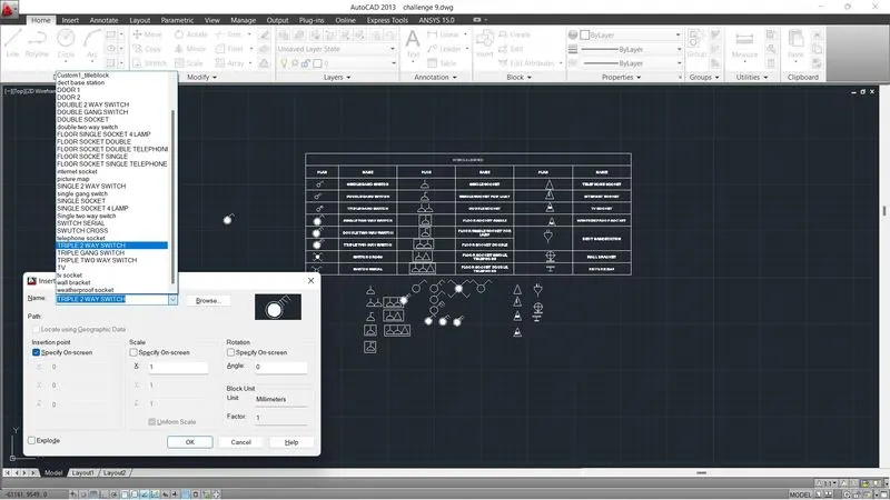
5. Use I (insert) command to fill the cell with label drawing, with base point defined at the time of block creation.
6. For Texting the name in the neighbouring cell, use INSERT tab, followed by field option and then selecting the field category from the list.
7. Name given at the time of block creation will come in the nearby cell.
This will lead to complete the Legends table.
FIGURE(D):
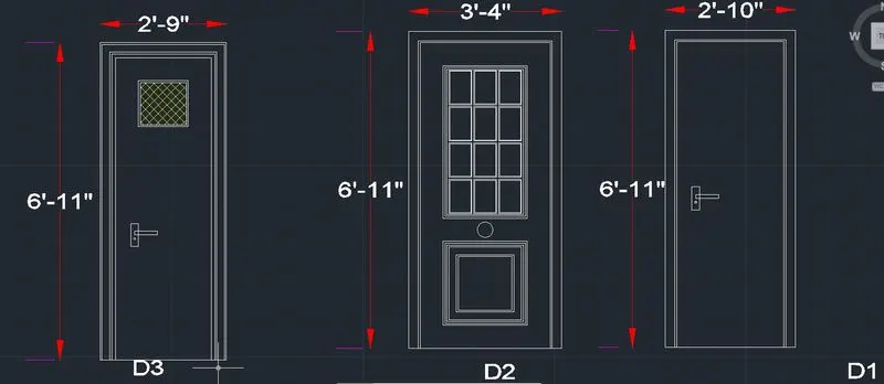
1. Here Drawing is made using feet unit so it’s better to use different file for eliminating the hodgepodge over the labelling.
- Here line command is mostly used along with offset command.
- Mullion thickness is around 2.5" over all the doors.
- Door frames around the panel is of 6".
- Here the inner panels of each door are of equal dimension with offset of 0.5" all around.
- Door locks are set from the bottom left-hand side of the door with TRA option of (4",3').
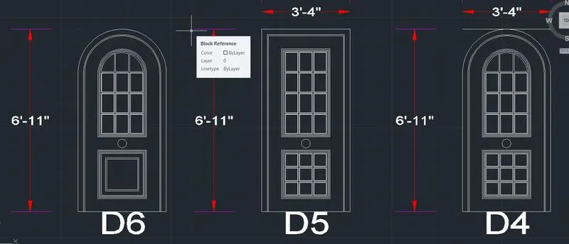
1. here line, arc (start, centre, length) & (start, end, direction), break at the single point, trim etc are used.
- DOOR D2 is copied several times with modification done using the commands given in 1st point.
- arc (start, centre, length) is used in drawing the curved mullion part of the door while (start, end, direction) is used to draw the inner panels.
- After Drawing each door, use DDEDIT command to text the name of that door.
- Create the Block using B command with names as texted.
- Use Insert command to insert the door where ever required in the same DWG name file.
FIGURE(e):
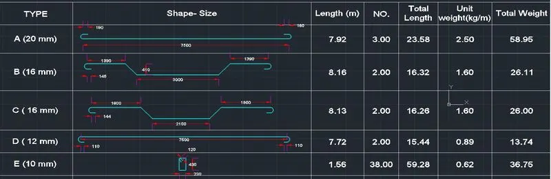
- Here all dimensions are in mm so it’s better to keep in mind the scale requirement.
- Here all the figures are drawn using line, arc(start, centre, length) command.
- After sketching the drawing, Create the block of each drawing with suitable base point.
- After creating all the blocks, Use INSERT table option in the ANNOTATE command in the HOME tab.
- Define the table properties (GENERAL (alignment, data type, precision etc.), TEXT (style, height), Margins) before proceeding for sketching.
- Use "I" Insert command to fill shape size column as mentioned in the attach screenshot above.
RESULT:
Here I have drawn the above sketches in the AUTOCAD software and attached in the form of JPEG format by taking the screenshots.