Creating Bar Bending schedule, Different Door types, and Creation of standard drawing templates using AutoCad
Week 9-Assignment 8-Module 2
Aim: To create a Bar Bending Schedule, Different Door Types and a Standard Drawing Templates using the proper drawing techniques and editing tools with the aid of AutoCAD.
Introduction:
- The topics covered in week 9 (titled Understanding external references and layout concept) which are somewhat essentials in plotting the requested geometries are as follows;
- External References, XREF is a shortened term for “external references”. The XREF feature allows you to attach external references to your drawing. External references can be in the format of other drawings, PDFs, images, point cloud data, and so on. The XREF feature works as a sort of overlay on your drawings; it isn’t a part of your drawing. XREF is also a tool for collaboration between many Disciplines working together on a Design Drawings etc.
- Hatching, is an artistic tecnique used to create tonal or shading effects by drawing closely spaced parallel lines. When lines are placed at an angle to one another, it is called cross-hatching. The Hatch command in AutoCAD is used to fill patterns inside an enclosed area. The patterns are hatched, gradient, and solid fill. The gradient patterns are defined as a smooth transition between two colors. There are several hatch patterns available in AutoCAD. We can choose the desired pattern from the list of the patterns according to the requirements. The number of hatch lines represented in any pattern can be adjusted with the help of the Hatch Pattern Scale.
Procedure:
A. Setting the Drawing Parameters;
- Set up the measurement units as metric measured in millimeters.
- To set up that, a much faster way is to type “units” in the command line and hit enter or space bar. The Drawing Units Dialog box will then pop up and measurement parameters will then set up in line with the requirements. Similar thing, you need to set up the dimension through the DDIM command.
- As for the gridlines, you may right click gridline icon in the status bar and go for the drafting settings. Under the Snap and Grid of the Drafting Settings Dialog box, you may set up the needed spacing of grids along its X and Y axis. “DS” command will also work to pop up the Drafting Settings Dialog box.
B. Starting the exercise;
- Combination and manipulation of all the different coordinate entry methods, drawing and modifying tools learned from weeks 1 to 9 were being used here in the completion of all the exercises given and result as pasted below.
- I have attached some screenshots while plotting the needed Drawings to show the procedure on how it was done to come out with the requested Design layouts.
C. Challenge;
- In general, below commands/functions were being used while working on the exercises.
- Units
- LIMMAX
- DDIM
- XLINE
- LINE
- PLINE
- OFFSET
- DIVIDE
- PTYPE
- MIRROR (MI)
- CIRCLE
- FILLET
- MTEXT
- DIM
- Manipulation with Ortho mode and Object Snaps
- LAYERS
- UTILITIES
- MATCHPROP
- ANNOTATION
- PDF IMPORT
- RAY
- DIMBREAK
- COPY
- SCALE
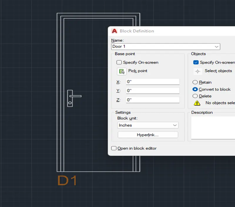
- BLOCK/ BLOCK EDIT
- WBLOCK
- ATTRIBUTES
- ARRAY
- HATCH
Challenge 1: Below are the brief steps while working on the requested templates.
- Set up the Units, Limits and Layers.
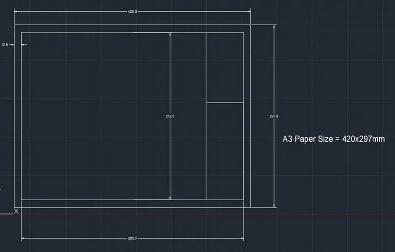
- Draw the Construction Line using XLINE, start from the bottom left. From this, set up the paper boundary considering A3 paper size of 420x297mm.
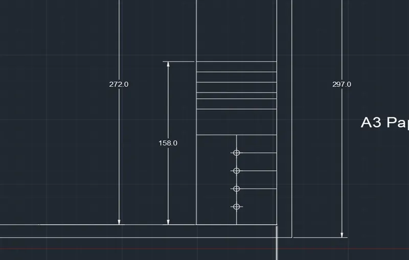
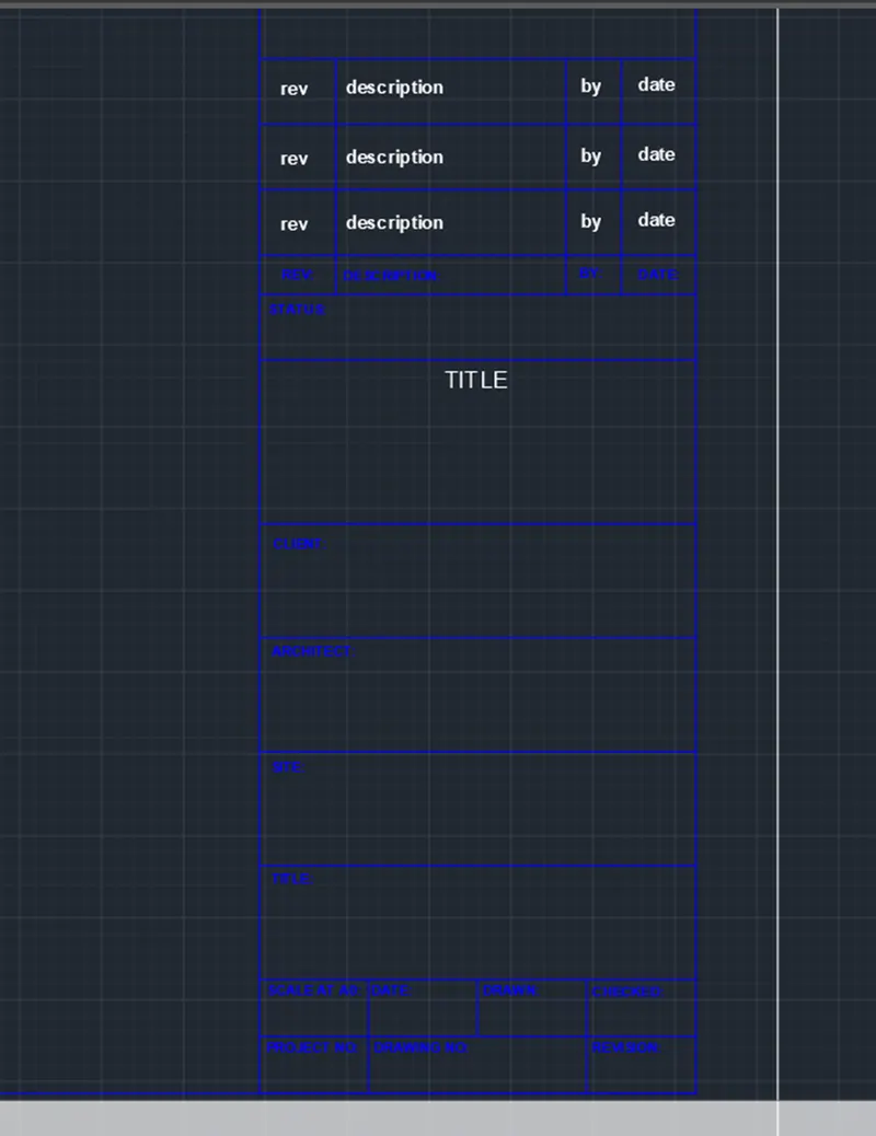
- Plot the dividing columns and rows using Construction Line or Draw commands together with the offset, trim, fillet and erase as applicable following the given sketches. Do this while some dimensions are applied to the borders to ensure realistic spacing of columns and rows of the templates as per the standard.
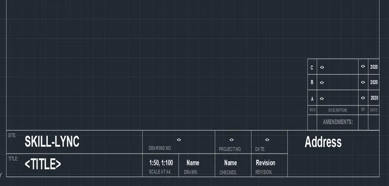
- Text to follow the aid of attributes function whenever needed.
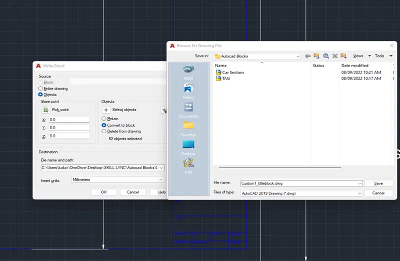
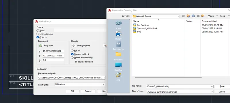
- Save the completed two templates as Custom1_titleblock and Custom2_titleblock respectively through the WBLOCK command so it can be useful to the future drawings as needed.
Challenge 2: Below are the brief steps while working on the requested geometries.
- Set up the Units, Limits and Layers.
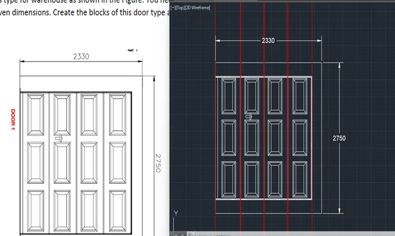
- Draw the Construction Line using XLINE, start from the bottom left and with proceed with the offset command following the dimensions given from the sketches provided.
- Make a proper division to the geometry using the DIVIDE and PTYPE command.
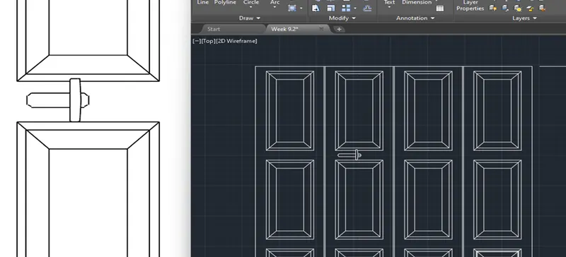
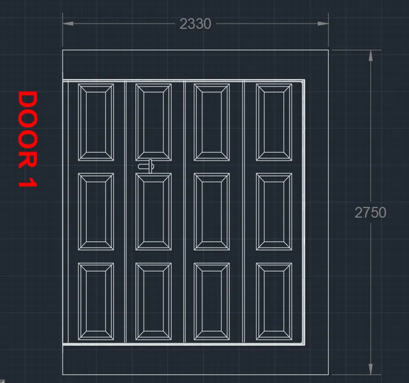
- Draw the first pattern using a rectangle and offset commands. From that you can use the Rectangular ARRAY command to duplicate the drawn pattern following the sketches.
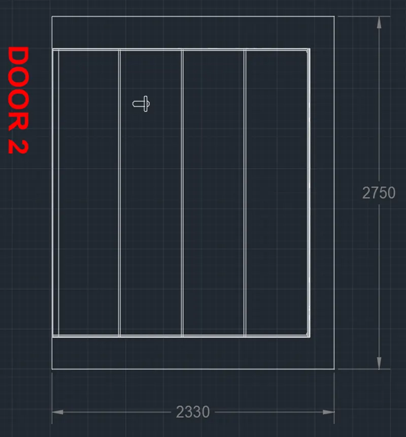
- Proceed with the other details such as the door handle dimensions and text.
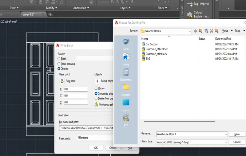
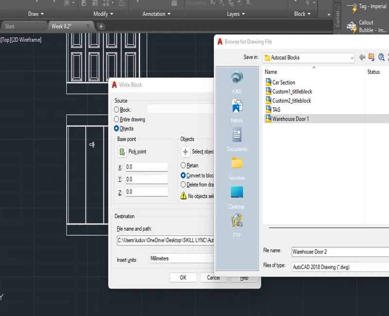
- Save the completed two Door 1 through the WBLOCK command so it can be useful to the future drawings as needed.
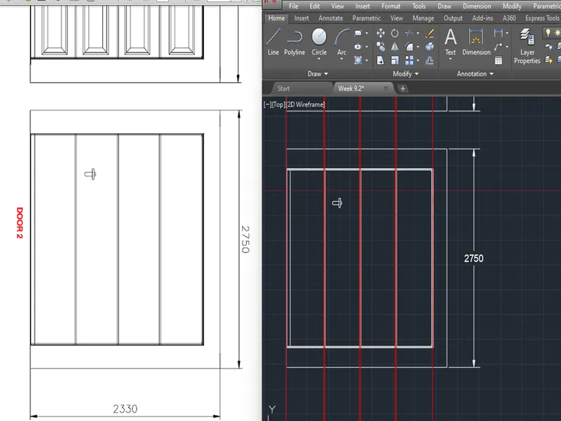
- As for the Door 2, it can be done quickly through by Manipulation of the XLINE command and orthographic projections method.
- Same with Door 1, save it through WBLOCK once completed.
Challenge 3: Below are the brief steps while working on the requested geometries.
- Set up the Units, Limits and Layers.
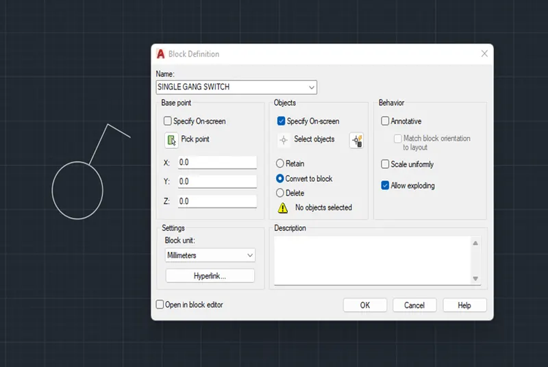
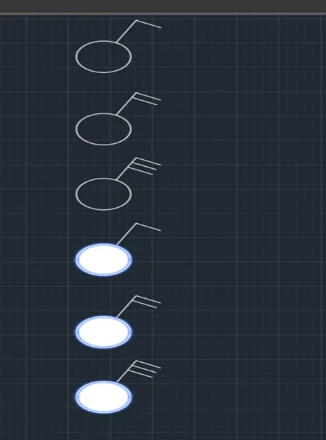
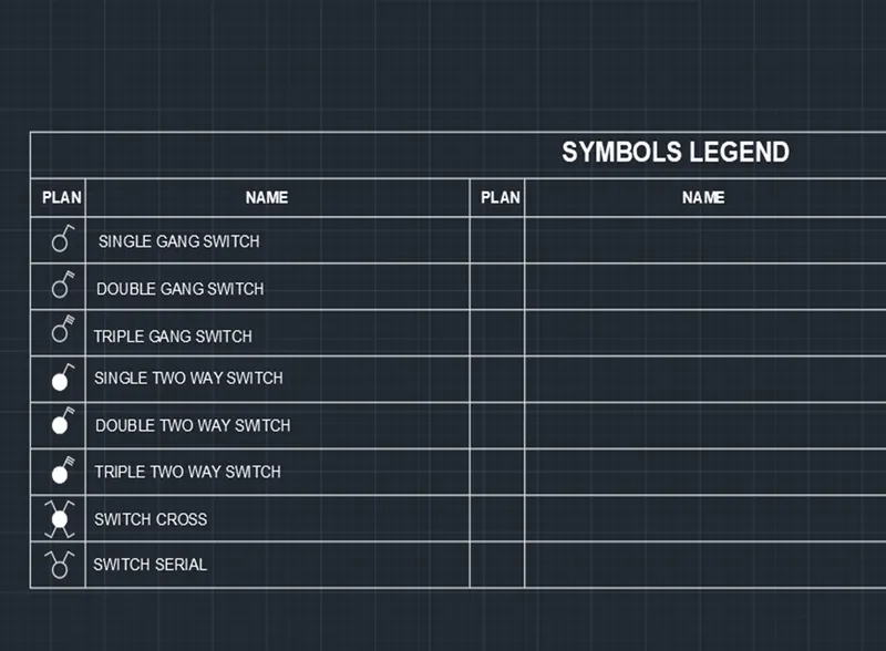
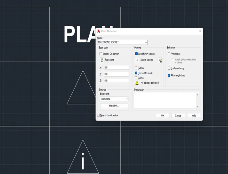
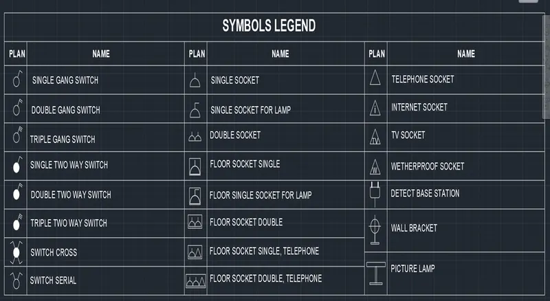
- Draw the symbols one by one and convert each one of them as BLOCK with the complete name provided in the sketch.
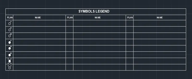
- Plot the table properly following the sketches to contain the created blocks. This can be done by the Draw line command with the aid of offset, trim etc.
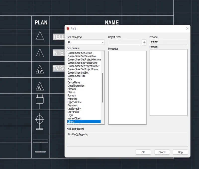
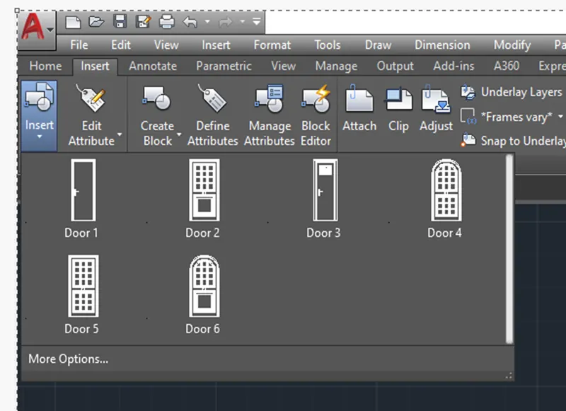
- Place the Blocks (using move or insert commands whichever you like) in place at the created table one by one including its name using the Field function.
- Proceed placing text to the heading and subheading.
Challenge 4: Below are the brief steps while working on the requested geometries.
- Set up the Units, Limits and Layers.
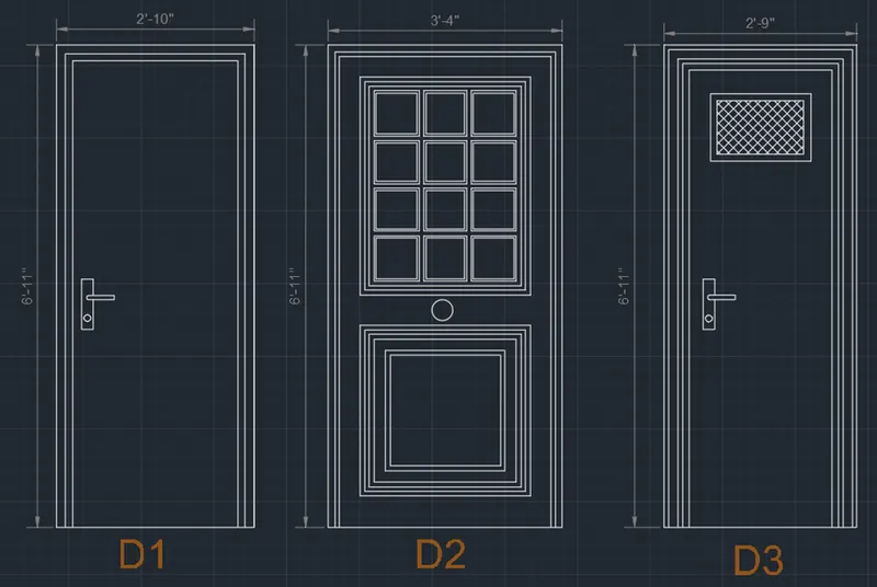
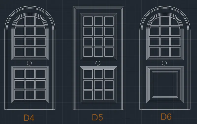
- Draw the door one by one and convert each one of them as BLOCK considering the given dimensions from the sketches as applicable otherwise assume as per the standard.
- In general, plotting the doors comprises of the Draw Line, offset, trim, circle, divide, rectangle, polygon, hatch, array etc.
- Proceed placing text and dimensions as applicable.

Challenge 5: Below are the brief steps while working on the requested geometries.
- Set up the Units, Limits and Layers.
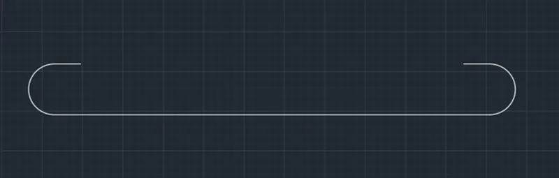
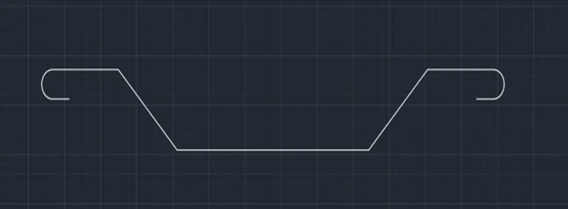
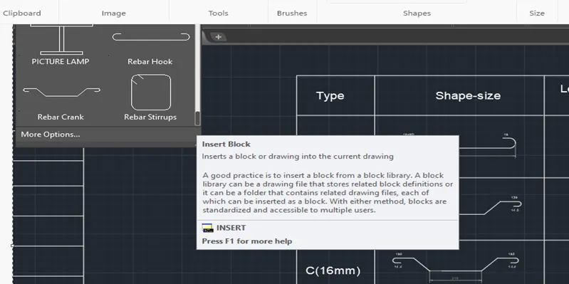
- Draw the rebar bending shapes one by one and convert each one of them as BLOCK.
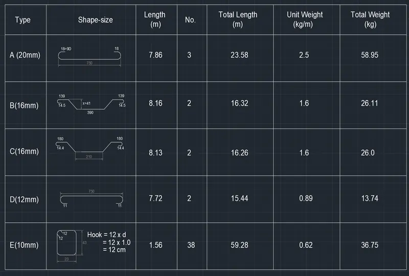
- Plot the table properly following the sketches to contain the created blocks. This can be done by the Draw line command with the aid of offset, trim etc.
- Place the Blocks (using move or insert commands whichever you like) in place at the created table one by one
- Proceed placing dimensions, text and further details as applicable.