Creating Bar Bending schedule, Different Door types, and Creation of standard drawing templates using AutoCad
AIM: - To Create the templates as shown in Figures
INTRODUCTION: - The given drawing is created using various tools in Autocad like lines, rectangle and modification tools like copy, move, offset, etc.
PROCEDURE: -
Before we start the drawings we need to set up the drawing as Imperial Template and the units into Engineering Units.
Following are the steps in order to set up the drawing as Imperial Template and the units into Engineering Units.
- Go to Application Menu or click CTRL + N (New)
- Click on New from the Application Menu
- A popup menu appears, click on the first tab known as Start from Scratch > Select Imperial
- Now click on the third tab known as Use a Wizard > Go to Advance setup > A Dialog box appears > Select the unit of measurement as Engineering > Press Next > select Angle as Decimal Degrees > Press Next > Select Angle Measure > Press Next > Select Angle Direction > Press Next > Select Area > Click Finish
- Set the page limit by entering Limits in the command tab. The lower left corner is specified as 0'-0.0" and the upper right corner is specified as 100',100'.
- In the Drawing Units dialog box, select 'Engineering' in Type; ' 0'-0.0" ' in Precision; and 'Inches' in Insertion scale.
- Click OK
- Now we are all set to go.
Now,
- Type D or DST or dimension in the command box.
- Press Enter.
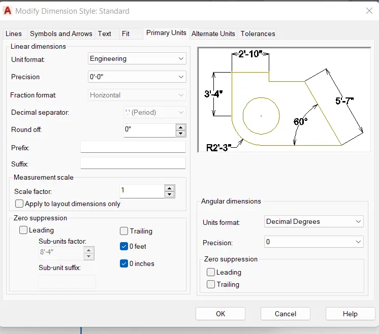
- Go Primary Units
- Set the precision to 0'0".
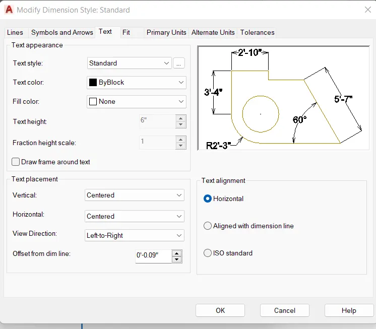
- Also set the Texts size as 6".
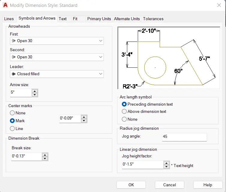
- And the arrow size as 5".
Now,
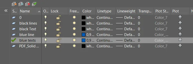
- Take some layer.
- Type LA or layer, a dialogue box appears.
- Select the following layers.
Now,
- Select the blue text layer .
- Draw a 35' vertical line
- Now draw a 17'10" horizontally line.
- Again draw a 35' vertical line in upward direction
- Press escape to close the command.

Now,
- Select the black text layer.
- Draw a horizontal line joining both the vertical lines.
- Do offset of 15"
- Again do offset of 2'8".
- Again do offset of 15".
- Now
- Select the black text layer.
- Draw a horizontal line joining both the vertical lines.
- Also draw the vertical lines to make the columns as per the requirement.
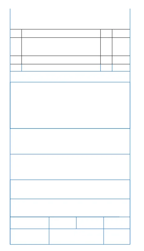
Now,
- Provide the texts as per requirement.
- So we have the following result.
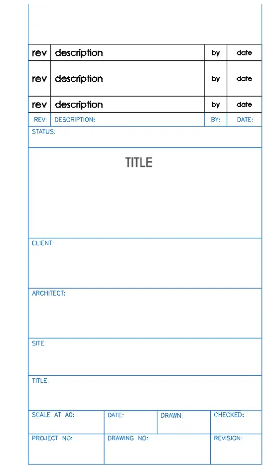
Now,
- Create the above template as a BLOCK.
- For this
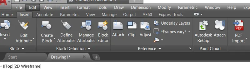
- Type BL or Block or
- Go to the ribbon
- Go to Insert and then
- Go to Create Block
- Create Block
Now,
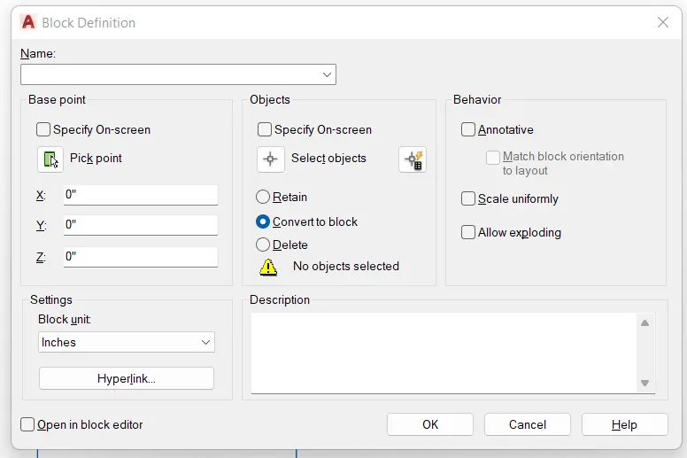
- Type BL or Block
- The following dailogue box appears.
Now,
- Give the block name as Custom1_titleblock as given in the question.
- Select the base point
- Then
- Select the entire Objects
- Click OK .
- So your Block has been created now.
Now,
- Press I or Insert
- The following dialogue box with your block appears.
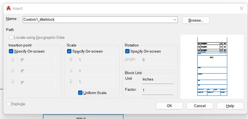
Hence the block named Custom1_titleblock has been successfully created.
---------------------------------------------------------------------------------------------------------------------------------------------------------
Now,
Draw the Custom2_titleblock
- For this all the procedures will be same
- Only change will in the dimesions.
So,
- Select the black text layer.
- Draw a horizontal line of length 29'3".
- Do offset of 16"
- Again do offset of 16".
- Now join the two offset lines by a vrtical lines..
- Now do vertical offsets of 11'9", 4'2", 2'1".
- Similarly do offset for the second line also.
- Now typr Tr or Trim to trim the unwanted lines.
- So we have the following template box.
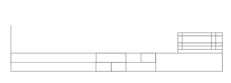
Now,
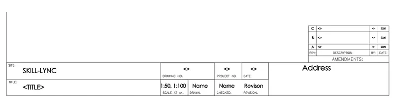
- Provide the texts as per requirement.
- So we have the following result.
Now,
- Create the above template as a BLOCK.
- For this
- Type BL or Block or
- Go to the ribbon
- Go to Insert and then
- Go to Create Block
- Create Block
Now,
- Type BL or Block
- The following dailogue box appears.
Now,
- Give the block name as Custom1_titleblock as given in the question.
- Select the base point
- Then
- Select the entire Objects
- Click OK .
- So your Block has been created now.
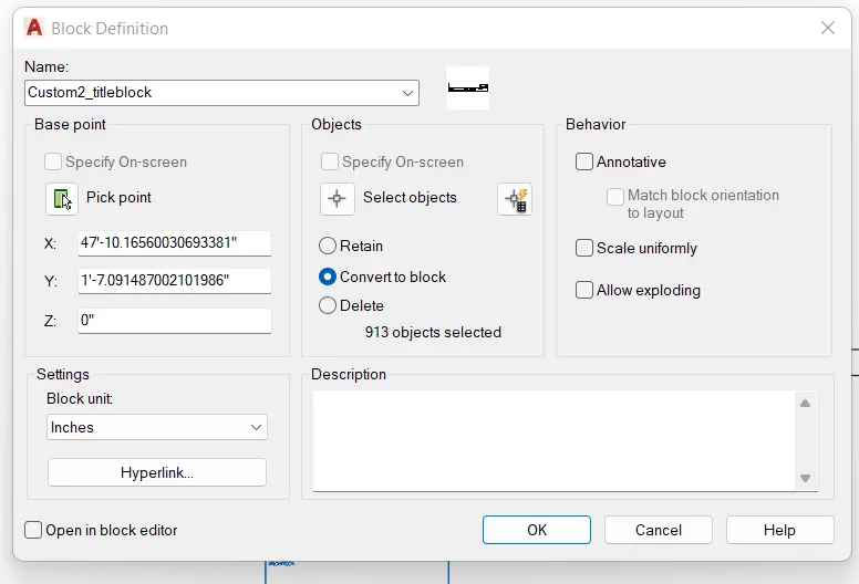
Now,
- Press I or Insert
- The following dialogue box with your block appears.
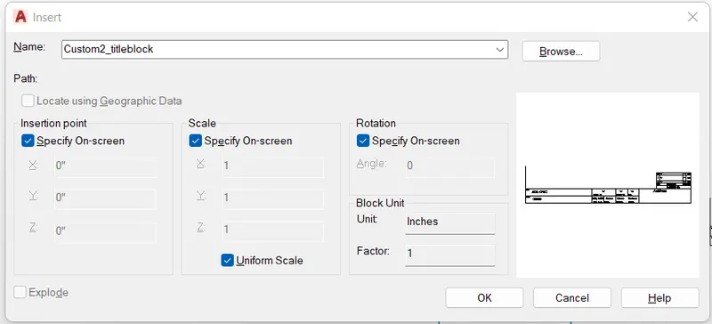
Hence the block named Custom2_titleblock has been successfully created.
---------------------------------------------------------------------------------------------------------------------------------------------------------
AIM: - To Create the doors type for warehouse as shown in the Figure.
INTRODUCTION: - The given drawing is created using various tools in Autocad like lines, rectangle and modification tools like copy, move, offset, etc.
PROCEDURE: -
Before we start the drawings we need to set up the drawing as Metric and the units into Decimal Units.
Following are the steps in order to set up the drawing as Imperial Template and the units into Engineering Units.
- Go to Application Menu or click CTRL + N (New)
- Click on New from the Application Menu
- A popup menu appears, click on the first tab known as Start from Scratch > Select Metric
- Now click on the third tab known as Use a Wizard > Go to Advance setup > A Dialog box appears > Select the unit of measurement as Decimal > Press Next > select Angle as Decimal Degrees > Press Next > Select Angle Measure > Press Next > Select Angle Direction > Press Next > Select Area > Click Finish
- Set the page limit by entering Limits in the command tab. The lower left corner is specified as 0,0 and the upper right corner is specified as 410, 297.
- In the Drawing Units dialog box, select 'Engineering' in Type; ' 0 ' in Precision; and 'Millimeter' in Insertion scale.
- Click OK
- Now we are all set to go.
Now,
- Import the drawing pdf which we are given to draw.
- Go to Ribbon Tab
- Click on Insert
- Then click on the PDF Import tool
- Import the required pdf.
Now,
- In order draw the drawing perfectly according to the size, we need to Scale it.
- So draw any dimension of the imported drawing like the size of the section wardrobe and draw it on the workspace by using line tool and direct distance method.
In order to Scale the Drawing,
- First select the entire imported drawing
- Select the base point
- Go to Reference option in the command box
- Select any dimension length of the imported drawing
- Then directing enter the scale length like 2750 or
- You can click on Points in the command box and select the two points of the line i.e., the first and the end point of the line which you have drawn.
- Now you are all set to go.
Now,
- Type D or DST or dimension in the command box.
- Press Enter.
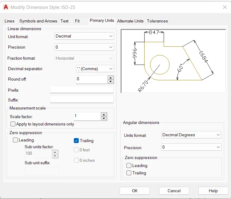
- Go Primary Units
- Set the precision to 0.
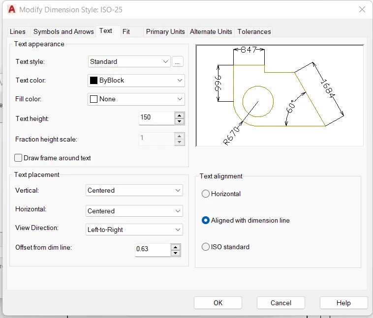
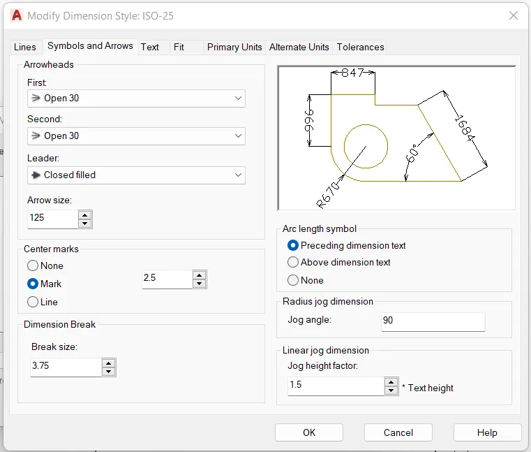
- Also set the Texts size as 150mm.
- And the arrow size as 125mm.
Now,
- Take some layer.
- Type LA or layer, a dialogue box appears.
- Select the following layers.
Now,
- Select the black line layer .
- Draw a 2720mm horizontally line
- Now draw a 3214mm vertically line.
- Again draw a 2720mm horizontally line
- Close the box.
- Press escape to close the command.
Now,
- Select the black text layer.
- select the vertical line.
- Do offset of 8mm
- Again do offset of 56mm.
- Again do offset of 577mm and 17mm.
- Repeat the above for 4 times.
- Press Escape to close the command.
Now,
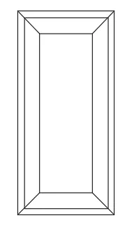
- Let us draw the inner panel of the door.
- Do a offset of 104mm of the vertical line.
- Draw a box of 758mm X 360mm.
- Do a offset of 25mm innerside of the box.
- Again do a offset 56mm of the inner side of the box.
- Type Tr or Trim to trim of the extended lines.
Now,
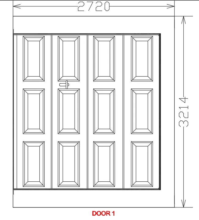
- Copy the above panel asper the the requirement.
- So we have the following result.
Now,
- Draw the door handle
- take the size as 148mm X 45mm.
Now, we have the following result,
Now,
- Create the above template as a BLOCK.
- For this
- Type BL or Block or
- Go to the ribbon
- Go to Insert and then
- Go to Create Block
- Create Block
Now,
- Type BL or Block
- The following dailogue box appears.
Now,
- Give the block name as Door1 as given in the question.
- Select the base point
- Then
- Select the entire Objects
- Click OK .
- So your Block has been created now.
Now,
- Press I or Insert
- The following dialogue box with your block appears.
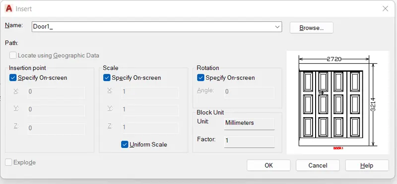
Hence the block named Door1_ has been successfully created.
Now,
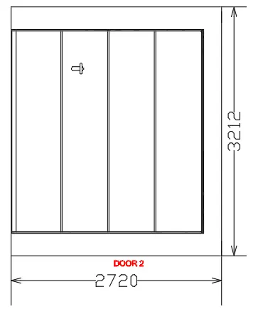
- Select the black line layer .
- Draw a 2720mm horizontally line
- Now draw a 3214mm vertically line.
- Again draw a 2720mm horizontally line
- Close the box.
- Press escape to close the command.
Now,
- Select the black text layer.
- select the vertical line.
- Do offset of 8mm
- Again do offset of 56mm.
- Again do offset of 577mm and 17mm.
- Repeat the above for 4 times.
- Press Escape to close the command.
Now,
- Draw the door handle
- take the size as 148mm X 45mm.
Now, we have the following result,
Now,
- Create the above template as a BLOCK.
- For this
- Type BL or Block or
- Go to the ribbon
- Go to Insert and then
- Go to Create Block
- Create Block
Now,
- Type BL or Block
- The following dailogue box appears.
Now,
- Give the block name as Door2_ as given in the question.
- Select the base point
- Then
- Select the entire Objects
- Click OK .
- So your Block has been created now.
Now,
- Press I or Insert
- The following dialogue box with your block appears.
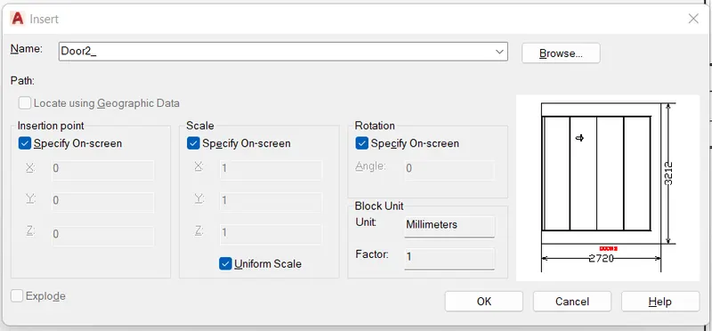
Hence the block named Door2_ has been successfully created.
---------------------------------------------------------------------------------------------------------------------------------------------------------
AIM: - To Create each symbol as a block with the name given in the legend using Autocad.
INTRODUCTION: - The given drawing is created using various tools in Autocad like lines, rectangle and modification tools like copy, move, offset, etc.
PROCEDURE: -
Before we start the drawings we need to set up the drawing as Imperial Template and the units into Engineering Units.
Following are the steps in order to set up the drawing as Imperial Template and the units into Engineering Units.
- Go to Application Menu or click CTRL + N (New)
- Click on New from the Application Menu
- A popup menu appears, click on the first tab known as Start from Scratch > Select Imperial
- Now click on the third tab known as Use a Wizard > Go to Advance setup > A Dialog box appears > Select the unit of measurement as Engineering > Press Next > select Angle as Decimal Degrees > Press Next > Select Angle Measure > Press Next > Select Angle Direction > Press Next > Select Area > Click Finish
- Set the page limit by entering Limits in the command tab. The lower left corner is specified as 0'-0.0" and the upper right corner is specified as 100',100'.
- In the Drawing Units dialog box, select 'Engineering' in Type; ' 0'-0.0" ' in Precision; and 'Inches' in Insertion scale.
- Click OK
- Now we are all set to go.
Now,
- Type D or DST or dimension in the command box.
- Press Enter.
- Go Primary Units
- Set the precision to 0'0".
- Also set the Texts size as 6".
- And the arrow size as 5".
Now,
- Take some layer.
- Type LA or layer, a dialogue box appears.
- Select the following layers.
Now,
- Import the drawing pdf which we are given to draw.
- Go to Ribbon Tab
- Click on Insert
- Then click on the PDF Import tool
- Import the required pdf.
Now,
- In order draw the drawing perfectly according to the size, we need to Scale it.
- So draw any dimension of the imported drawing like the size of the section wardrobe and draw it on the workspace by using line tool and direct distance method.
In order to Scale the Drawing,
- First select the entire imported drawing
- Select the base point
- Go to Reference option in the command box
- Select any dimension length of the imported drawing
- Then directing enter the scale length like 6".
- You can click on Points in the command box and select the two points of the line i.e., the first and the end point of the line which you have drawn.
- Now you are all set to go.
Now,
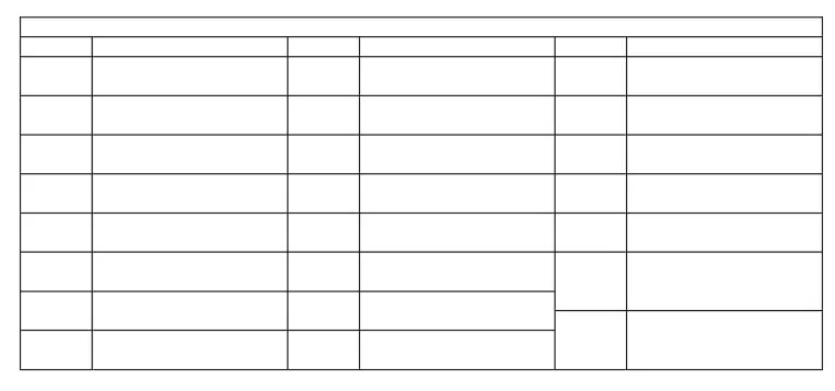
- Draw a vertical line 25'11"
- Draw a horizontal line 59'1".
- Draw a vertical line 25'11".
- Draw a horizontal line 59'1".
- Click Escape to close the command.
Now,
- Type O or Offset .
- Do a vertical offset of 5'3"
- Again
- Do a vertical offset of 14'5"
- Do a vertical offset of 5'3"
- Do a vertical offset of 14'5"
- Do a vertical offset of 5'3"
- Do a vertical offset of 14'5".
Now,
- Type O or Offset .
- Do a horizontal offset of 1'5".
- Again
- Do a horizontal offset of 1'6"
- Do a horizontal offset of 2'10"
- Do this offset 7 times.
- Press Escape to close the command.
Now, Draw the Symbols
- Draw a circle of 3".
- Then draw a daigonal line of length 11".
- Again draw a line og 5".

Now,
- Create the above Symbol as a BLOCK.
- For this
- Type BL or Block or
- Go to the ribbon
- Go to Insert and then
- Go to Create Block
- Create Block
Now,
- Type BL or Block
- The following dailogue box appears.
Now,
- Give the block name as SINGLE GANG SWITCH as given in the question.
- Select the base point
- Then
- Select the entire Objects
- Click OK .
- So your Block has been created now.
Now,
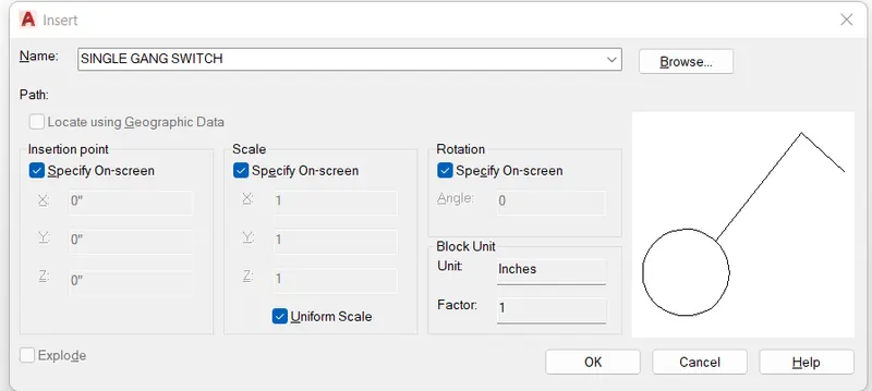
- Press I or Insert
- The following dialogue box with your block appears.
Now, put the above drawn block in the table..
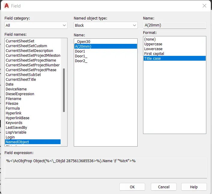
- To put the name of the block without using Mtext.
- Go to Insert > Field
- Then select the required Block name.

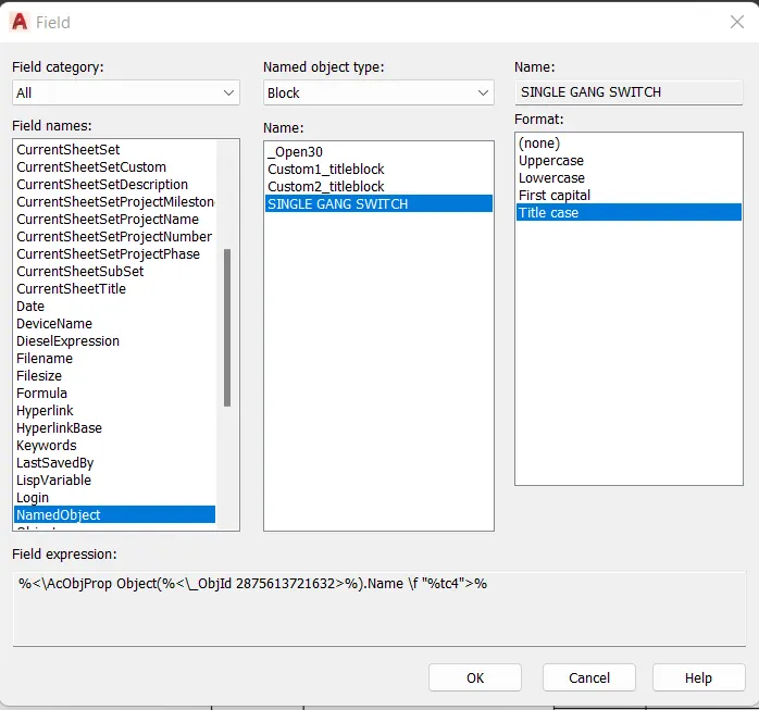
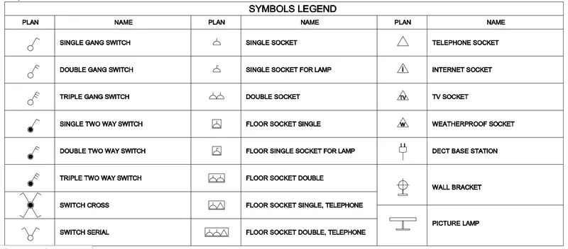
Similarly, all the other symbols are also drawn and made into block in the same way.
Now, we have the following result,
-----------------------------------------------------------------------------------------------------------------------------------------------------------
AIM: - To Create the door type for residential building as a block using AutoCAD.
INTRODUCTION: - The given drawing is created using various tools in Autocad like lines, rectangle and modification tools like copy, move, offset, etc.
PROCEDURE: -
Before we start the drawings we need to set up the drawing as Imperial Template and the units into Engineering Units.
Following are the steps in order to set up the drawing as Imperial Template and the units into Engineering Units.
- Go to Application Menu or click CTRL + N (New)
- Click on New from the Application Menu
- A popup menu appears, click on the first tab known as Start from Scratch > Select Imperial
- Now click on the third tab known as Use a Wizard > Go to Advance setup > A Dialog box appears > Select the unit of measurement as Engineering > Press Next > select Angle as Decimal Degrees > Press Next > Select Angle Measure > Press Next > Select Angle Direction > Press Next > Select Area > Click Finish
- Set the page limit by entering Limits in the command tab. The lower left corner is specified as 0'-0.0" and the upper right corner is specified as 100',100'.
- In the Drawing Units dialog box, select 'Engineering' in Type; ' 0'-0.0" ' in Precision; and 'Inches' in Insertion scale.
- Click OK
- Now we are all set to go.
Now,
- Type D or DST or dimension in the command box.
- Press Enter.
- Go Primary Units
- Set the precision to 0'0".
- Also set the Texts size as 6".
- And the arrow size as 5".
Now,
- Take some layer.
- Type LA or layer, a dialogue box appears.
- Select the following layers.
Now,
- Import the drawing pdf which we are given to draw.
- Go to Ribbon Tab
- Click on Insert
- Then click on the PDF Import tool
- Import the required pdf.
Now,
- In order draw the drawing perfectly according to the size, we need to Scale it.
- So draw any dimension of the imported drawing like the size of the section wardrobe and draw it on the workspace by using line tool and direct distance method.
In order to Scale the Drawing,
- First select the entire imported drawing
- Select the base point
- Go to Reference option in the command box
- Select any dimension length of the imported drawing
- Then directing enter the scale length like 6".
- You can click on Points in the command box and select the two points of the line i.e., the first and the end point of the line which you have drawn.
- Now you are all set to go.
Now,
- Select the black line layer .
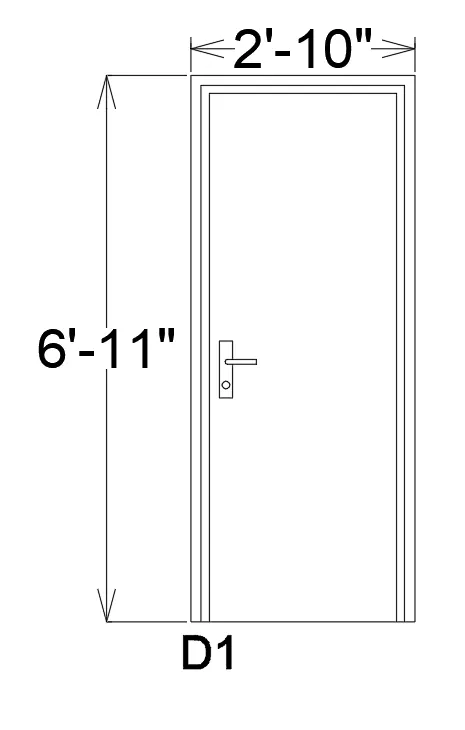
- Draw a 2'10" horizontally line
- Now draw a 6'11" vertically line.
- Again draw a 2'10" horizontally line
- Close the box.
- Press escape to close the command.
Now,
- Select the black text layer.
- select the vertical line.
- Do offset of 2" inside
- Again do offset of 2" inside
- Trim off the extra part.
Now,
- Copy the above panel asper the the requirement.
- So we have the following result.
Now,
- Draw the door handle
- take the size as 9" X 2".
Now, we have the following results,
Now,
- Create the above template as a BLOCK.
- For this
- Type BL or Block or
- Go to the ribbon
- Go to Insert and then
- Go to Create Block
- Create Block
Now,
- Type BL or Block
- The following dailogue box appears.
Now,
- Give the block name as D1 given in the question.
- Select the base point
- Then
- Select the entire Objects
- Click OK .
- So your Block has been created now.
Now,
- Press I or Insert
- The following dialogue box with your block appears.
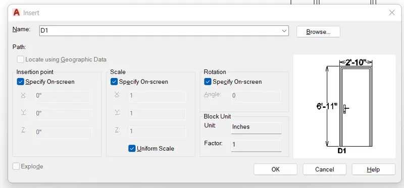
Hence the block named D1 has been successfully created.
---------------------------------------------------------------------------------------------------------------------------------------------------
Now,
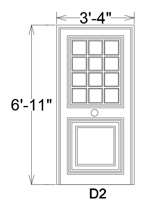
Draw the D2
- For this all the procedures will be same
- Only change will in the dimesions.
Now,
- Select the black line layer .
- Draw a 3'4" horizontally line
- Now draw a 6'11" vertically line.
- Again draw a 3'4" horizontally line
- Close the box.
- Press escape to close the command.
Now,
- Select the black text layer.
- select the vertical line.
- Do offset of 2" inside
- Again do offset of 2" inside
- Trim off the extra part.
Now,
- Copy the above panel asper the the requirement.
- So we have the following result.
Now,
- Draw the circle
- Take the size of the dia as 4".
Now, we have the following results,
Now,
- Create the above template as a BLOCK.
- For this
- Type BL or Block or
- Go to the ribbon
- Go to Insert and then
- Go to Create Block
- Create Block
Now,
- Type BL or Block
- The following dailogue box appears.
Now,
- Give the block name as D2 given in the question.
- Select the base point
- Then
- Select the entire Objects
- Click OK .
- So your Block has been created now.
Now,
- Press I or Insert
- The following dialogue box with your block appears.
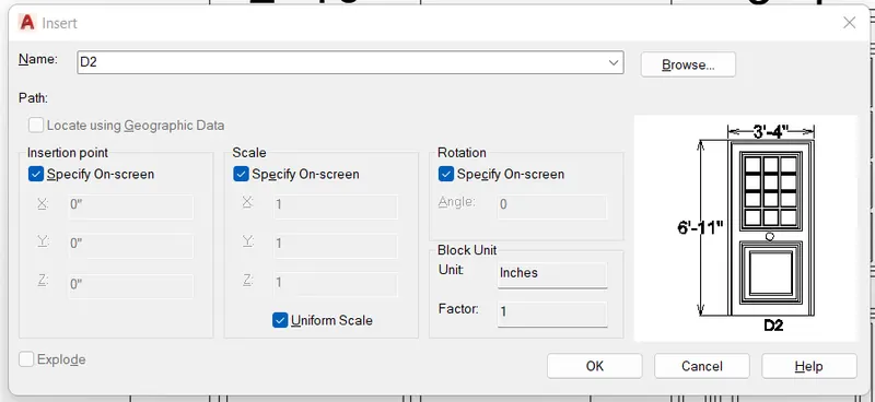
Hence the block named D2 has been successfully created.
---------------------------------------------------------------------------------------------------------------------------------------------------
Now,
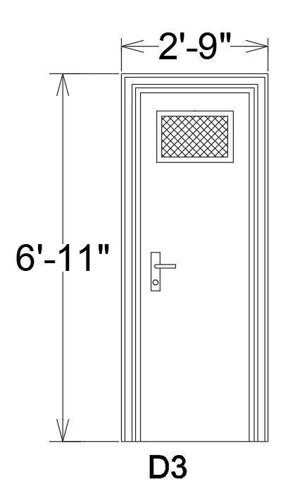
Draw the D3
- For this all the procedures will be same
- Only change will in the dimesions.
Now,
- Select the black line layer .
- Draw a 2'9" horizontally line
- Now draw a 6'11" vertically line.
- Again draw a 2'9" horizontally line
- Close the box.
- Press escape to close the command.
Now,
- Select the black text layer.
- select the vertical line.
- Do offset of 2" inside
- Again do offset of 2" inside
- Trim off the extra part.
Now,
- Copy the above panel asper the the requirement.
- So we have the following result.
Now,
- Draw the circle
- Take the size of the dia as 4".
Now, we have the following results,
Now,
- Create the above template as a BLOCK.
- For this
- Type BL or Block or
- Go to the ribbon
- Go to Insert and then
- Go to Create Block
- Create Block
Now,
- Type BL or Block
- The following dailogue box appears.
Now,
- Give the block name as D2 given in the question.
- Select the base point
- Then
- Select the entire Objects
- Click OK .
- So your Block has been created now.
Now,
- Press I or Insert
- The following dialogue box with your block appears.
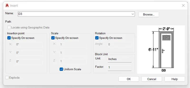
Hence the block named D3 has been successfully created.
---------------------------------------------------------------------------------------------------------------------------------------------------
Now,
Draw the D4
- For this all the procedures will be same
- Only change will in the dimesions.
Now,
- Select the black line layer .
- Draw a 3'4" horizontally line
- Now draw a 6'11" vertically line.
- Again draw a 3'4" horizontally line
- Close the box.
- Press escape to close the command.
Now,
- Select the black text layer.
- select the vertical line.
- Do offset of 2" inside
- Again do offset of 2" inside
- Trim off the extra part.
Now,
- Copy the above panel asper the the requirement.
- So we have the following result.
Now,
- Draw the circle
- Take the size of the dia as 4".
Now, we have the following results,
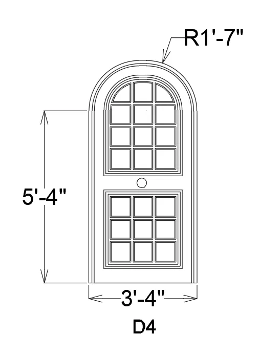
Now,
- Create the above template as a BLOCK.
- For this
- Type BL or Block or
- Go to the ribbon
- Go to Insert and then
- Go to Create Block
- Create Block
Now,
- Type BL or Block
- The following dailogue box appears.
Now,
- Give the block name as D4 given in the question.
- Select the base point
- Then
- Select the entire Objects
- Click OK .
- So your Block has been created now.
Now,
- Press I or Insert
- The following dialogue box with your block appears.
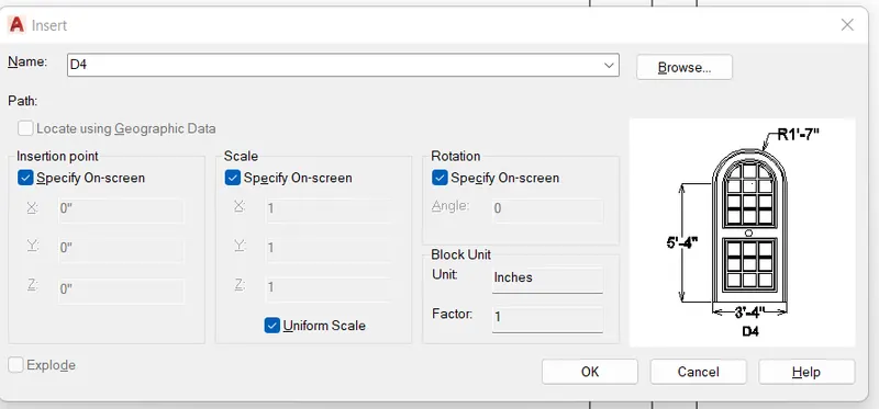
Hence the block named D4 has been successfully created.
----------------------------------------------------------------------------------------------------------------------------------------------------------
Now,
Draw the D5
- For this all the procedures will be same
- Only change will in the dimesions.
Now,
- Select the black line layer .
- Draw a 3'4" horizontally line
- Now draw a 6'11" vertically line.
- Again draw a 3'4" horizontally line
- Close the box.
- Press escape to close the command.
Now,
- Select the black text layer.
- select the vertical line.
- Do offset of 2" inside
- Again do offset of 2" inside
- Trim off the extra part.
Now,
- Copy the above panel asper the the requirement.
- So we have the following result.
Now,
- Draw the circle
- Take the size of the dia as 4".
Now, we have the following results,
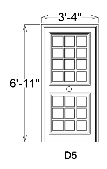
Now,
- Create the above template as a BLOCK.
- For this
- Type BL or Block or
- Go to the ribbon
- Go to Insert and then
- Go to Create Block
- Create Block
Now,
- Type BL or Block
- The following dailogue box appears.
Now,
- Give the block name as D5 given in the question.
- Select the base point
- Then
- Select the entire Objects
- Click OK .
- So your Block has been created now.
Now,
- Press I or Insert
- The following dialogue box with your block appears.
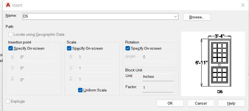
Hence the block named D5 has been successfully created.
----------------------------------------------------------------------------------------------------------------------------------------------------
Now,
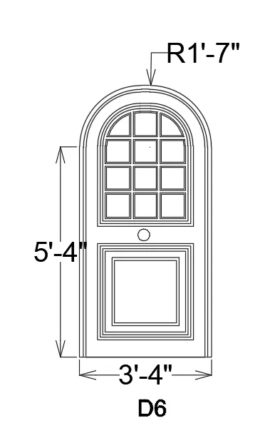
Draw the D6
- For this all the procedures will be same
- Only change will in the dimesions.
Now,
- Select the black line layer .
- Draw a 3'4" horizontally line
- Now draw a 6'11" vertically line.
- Again draw a 3'4" horizontally line
- Close the box.
- Press escape to close the command.
Now,
- Select the black text layer.
- select the vertical line.
- Do offset of 2" inside
- Again do offset of 2" inside
- Trim off the extra part.
Now,
- Copy the above panel asper the the requirement.
- So we have the following result.
Now,
- Draw the circle
- Take the size of the dia as 4".
Now, we have the following results,
Now,
- Create the above template as a BLOCK.
- For this
- Type BL or Block or
- Go to the ribbon
- Go to Insert and then
- Go to Create Block
- Create Block
Now,
- Type BL or Block
- The following dailogue box appears.
Now,
- Give the block name as D4 given in the question.
- Select the base point
- Then
- Select the entire Objects
- Click OK .
- So your Block has been created now.
Now,
- Press I or Insert
- The following dialogue box with your block appears.
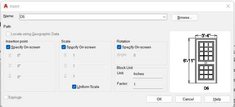
Hence the block named D6 has been successfully created.
--------------------------------------------------------------------------------------------------------------------------------------------------
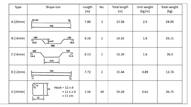
AIM: - To Create each shape as a block as shown in the Figure using Autocad.
INTRODUCTION: - The given drawing is created using various tools in Autocad like lines, rectangle and modification tools like copy, move, offset, etc.
PROCEDURE: -
Before we start the drawings we need to set up the drawing as Metric and the units into Decimal Units.
Following are the steps in order to set up the drawing as Imperial Template and the units into Engineering Units.
- Go to Application Menu or click CTRL + N (New)
- Click on New from the Application Menu
- A popup menu appears, click on the first tab known as Start from Scratch > Select Metric
- Now click on the third tab known as Use a Wizard > Go to Advance setup > A Dialog box appears > Select the unit of measurement as Decimal > Press Next > select Angle as Decimal Degrees > Press Next > Select Angle Measure > Press Next > Select Angle Direction > Press Next > Select Area > Click Finish
- Set the page limit by entering Limits in the command tab. The lower left corner is specified as 0,0 and the upper right corner is specified as 410, 297.
- In the Drawing Units dialog box, select 'Engineering' in Type; ' 0 ' in Precision; and 'Millimeter' in Insertion scale.
- Click OK
- Now we are all set to go.
Now,
- Import the drawing pdf which we are given to draw.
- Go to Ribbon Tab
- Click on Insert
- Then click on the PDF Import tool
- Import the required pdf.
Now,
- In order draw the drawing perfectly according to the size, we need to Scale it.
- So draw any dimension of the imported drawing like the size of the section wardrobe and draw it on the workspace by using line tool and direct distance method.
In order to Scale the Drawing,
- First select the entire imported drawing
- Select the base point
- Go to Reference option in the command box
- Select any dimension length of the imported drawing
- Then directing enter the scale length like 2750 or
- You can click on Points in the command box and select the two points of the line i.e., the first and the end point of the line which you have drawn.
- Now you are all set to go.
Now,
- Type D or DST or dimension in the command box.
- Press Enter.
- Go Primary Units
- Set the precision to 0.
- Also set the Texts size as 150mm.
- And the arrow size as 125mm.
Now,
- Take some layer.
- Type LA or layer, a dialogue box appears.
- Select the following layers.
Now,
- Import the drawing pdf which we are given to draw.
- Go to Ribbon Tab
- Click on Insert
- Then click on the PDF Import tool
- Import the required pdf.
Now,
- In order draw the drawing perfectly according to the size, we need to Scale it.
- So draw any dimension of the imported drawing like the size of the section wardrobe and draw it on the workspace by using line tool and direct distance method.
In order to Scale the Drawing,
- First select the entire imported drawing
- Select the base point
- Go to Reference option in the command box
- Select any dimension length of the imported drawing
- Then directing enter the scale length like 6".
- You can click on Points in the command box and select the two points of the line i.e., the first and the end point of the line which you have drawn.
- Now you are all set to go.
Now,
- Draw a vertical line 25'11"
- Draw a horizontal line 59'1".
- Draw a vertical line 25'11".
- Draw a horizontal line 59'1".
- Click Escape to close the command.
Now,
- Type O or Offset .
- Do a vertical offset of 5'3"
- Again
- Do a vertical offset of 14'5"
- Do a vertical offset of 5'3"
- Do a vertical offset of 14'5"
- Do a vertical offset of 5'3"
- Do a vertical offset of 14'5".
Now,
- Type O or Offset .
- Do a horizontal offset of 1'5".
- Again
- Do a horizontal offset of 1'6"
- Do a horizontal offset of 2'10"
- Do this offset 7 times.
- Press Escape to close the command.
Now, Draw the Symbols
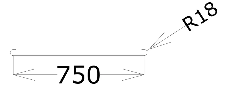
- Draw a line of length 750mm.
- Then draw a circle of radius 18mm.
- So we have
Now,
- Create the above Symbol as a BLOCK.
- For this
- Type BL or Block or
- Go to the ribbon
- Go to Insert and then
- Go to Create Block
- Create Block
Now,
- Type BL or Block
- The following dailogue box appears.
Now,
- Give the block name as SINGLE GANG SWITCH as given in the question.
- Select the base point
- Then
- Select the entire Objects
- Click OK .
- So your Block has been created now.
Now,
- Press I or Insert
- The following dialogue box with your block appears.
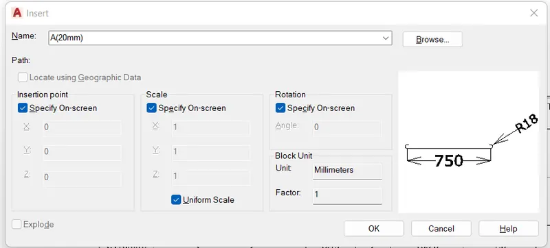
Now, put the above drawn block in the table..
- To put the name of the block without using Mtext.
- Go to Insert > Field
- Then select the required Block name.
Similarly, all the other symbols are also drawn and made into block in the same way.
Now, we have the following result,
-----------------------------------------------------------------------------------------------------------------------------------------------------------